US6274892B1 - Devices formable by low temperature direct bonding - Google Patents
Devices formable by low temperature direct bonding Download PDFInfo
- Publication number
- US6274892B1 US6274892B1 US09/036,838 US3683898A US6274892B1 US 6274892 B1 US6274892 B1 US 6274892B1 US 3683898 A US3683898 A US 3683898A US 6274892 B1 US6274892 B1 US 6274892B1
- Authority
- US
- United States
- Prior art keywords
- buffer
- substrate
- lifetime killing
- layer
- emitter
- Prior art date
- Legal status (The legal status is an assumption and is not a legal conclusion. Google has not performed a legal analysis and makes no representation as to the accuracy of the status listed.)
- Expired - Fee Related
Links
Images


Classifications
-
- H—ELECTRICITY
- H10—SEMICONDUCTOR DEVICES; ELECTRIC SOLID-STATE DEVICES NOT OTHERWISE PROVIDED FOR
- H10D—INORGANIC ELECTRIC SEMICONDUCTOR DEVICES
- H10D12/00—Bipolar devices controlled by the field effect, e.g. insulated-gate bipolar transistors [IGBT]
- H10D12/01—Manufacture or treatment
- H10D12/031—Manufacture or treatment of IGBTs
- H10D12/032—Manufacture or treatment of IGBTs of vertical IGBTs
- H10D12/038—Manufacture or treatment of IGBTs of vertical IGBTs having a recessed gate, e.g. trench-gate IGBTs
-
- H—ELECTRICITY
- H10—SEMICONDUCTOR DEVICES; ELECTRIC SOLID-STATE DEVICES NOT OTHERWISE PROVIDED FOR
- H10D—INORGANIC ELECTRIC SEMICONDUCTOR DEVICES
- H10D12/00—Bipolar devices controlled by the field effect, e.g. insulated-gate bipolar transistors [IGBT]
- H10D12/01—Manufacture or treatment
- H10D12/031—Manufacture or treatment of IGBTs
- H10D12/032—Manufacture or treatment of IGBTs of vertical IGBTs
-
- H—ELECTRICITY
- H10—SEMICONDUCTOR DEVICES; ELECTRIC SOLID-STATE DEVICES NOT OTHERWISE PROVIDED FOR
- H10D—INORGANIC ELECTRIC SEMICONDUCTOR DEVICES
- H10D18/00—Thyristors
- H10D18/01—Manufacture or treatment
-
- H—ELECTRICITY
- H10—SEMICONDUCTOR DEVICES; ELECTRIC SOLID-STATE DEVICES NOT OTHERWISE PROVIDED FOR
- H10D—INORGANIC ELECTRIC SEMICONDUCTOR DEVICES
- H10D30/00—Field-effect transistors [FET]
- H10D30/01—Manufacture or treatment
- H10D30/012—Manufacture or treatment of static induction transistors [SIT], e.g. permeable base transistors [PBT]
-
- H—ELECTRICITY
- H10—SEMICONDUCTOR DEVICES; ELECTRIC SOLID-STATE DEVICES NOT OTHERWISE PROVIDED FOR
- H10D—INORGANIC ELECTRIC SEMICONDUCTOR DEVICES
- H10D30/00—Field-effect transistors [FET]
- H10D30/01—Manufacture or treatment
- H10D30/021—Manufacture or treatment of FETs having insulated gates [IGFET]
- H10D30/028—Manufacture or treatment of FETs having insulated gates [IGFET] of double-diffused metal oxide semiconductor [DMOS] FETs
- H10D30/0291—Manufacture or treatment of FETs having insulated gates [IGFET] of double-diffused metal oxide semiconductor [DMOS] FETs of vertical DMOS [VDMOS] FETs
-
- H—ELECTRICITY
- H10—SEMICONDUCTOR DEVICES; ELECTRIC SOLID-STATE DEVICES NOT OTHERWISE PROVIDED FOR
- H10D—INORGANIC ELECTRIC SEMICONDUCTOR DEVICES
- H10D62/00—Semiconductor bodies, or regions thereof, of devices having potential barriers
- H10D62/80—Semiconductor bodies, or regions thereof, of devices having potential barriers characterised by the materials
- H10D62/83—Semiconductor bodies, or regions thereof, of devices having potential barriers characterised by the materials being Group IV materials, e.g. B-doped Si or undoped Ge
- H10D62/832—Semiconductor bodies, or regions thereof, of devices having potential barriers characterised by the materials being Group IV materials, e.g. B-doped Si or undoped Ge being Group IV materials comprising two or more elements, e.g. SiGe
- H10D62/8325—Silicon carbide
-
- H—ELECTRICITY
- H10—SEMICONDUCTOR DEVICES; ELECTRIC SOLID-STATE DEVICES NOT OTHERWISE PROVIDED FOR
- H10P—GENERIC PROCESSES OR APPARATUS FOR THE MANUFACTURE OR TREATMENT OF DEVICES COVERED BY CLASS H10
- H10P10/00—Bonding of wafers, substrates or parts of devices
- H10P10/12—Bonding of semiconductor wafers or semiconductor substrates to semiconductor wafers or semiconductor substrates
- H10P10/128—Bonding of semiconductor wafers or semiconductor substrates to semiconductor wafers or semiconductor substrates by direct semiconductor to semiconductor bonding
Definitions
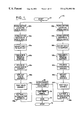
- Side B may be polished and cleaned at Block 60 a taking care to minimize hydrocarbon voids and to reduce oxygen at the ultimate bonding interface. If metal is exposed on the surface, such as metal bonding pads, it may be advantageous to protect the metal from chemicals used in the cleaning of the wafers.
- One possible technique is to deposit a protective insulator layer that is resistant to the chemicals. The insulator layer could be removed after the wafers are bonded.
- the polishing such as using chemical mechanical polishing (CMP), may be used so that the side B surface has a root-mean-square (RMS) surface roughness less than about 1 nm. A surface roughness of less than about 10 nm is desirable for direct bonding the two substrates together.
- CMP chemical mechanical polishing
- the oxide layer may be desirably less than about 1 nm for satisfactory operation.
- the wafer typically includes a plurality of individual die thereon, these die can be tested (Block 64 a ) and the results later used to correlate with the second substrate to thereby increase the overall process yield.
- Yet another aspect of the invention relates to cutting the wafer along the outer streets (Block 66 a ). This will allow the precise alignment of the first and second wafers at Block 68 .
- the wafers once properly aligned, may be bonded by bringing same together at a center point and allowing atomic bonding to tend to bring the wafers together extending outwardly from the center. In some embodiments, a relatively high or ultrahigh vacuum may be desirable for the bonding process.
- the two wafers may also be aligned based upon the crystal orientations of the two wafers as will also be appreciated by those skilled in the art.
- the direct bonding after processing of the invention can be used to implement high performance IGBTs, MOSFETs, and MCTs, for example.
- the directed bonded devices may also have an ultra-thin N+ buffer layer which will provide significant improvements in the turn-off time compared to alternate approaches as described in greater detail below.
- the direct bonded IGBTs and MCTs will have a novel feature of positive temperature coefficient for forward voltage which arises from a negative temperature coefficient for current gain.
- a silicon MOSFET current control power device in a first substrate to a second substrate that includes SiC material.
- Other candidates for the material of the second substrate may include GaN, InP, and GaAs.
- Wide bandgap materials, such as SiC generally have a high critical field of electrical breakdown, and also have high saturated drift velocities. Thus, wide bandgap materials are often desirable to be used to support most of the high voltage drop across depletion layers in power devices.
- Another reason for selecting a material for the second substrate to be different than silicon is to provide a high thermal conductivity.
- SiC which has a three times higher thermal conductivity than silicon may be used for the second substrate.
- two or more non-silicon substrates may be processed and bonded in accordance with the present invention.
- a grid of silicide lines at the interface between the two substrates 125 , 122 can be used to form a permeable base transistor in which reverse biased Schottky diodes are used to modulate the current flow perpendicular to the grid of silicide lines 123 as will be readily appreciated by those skilled in the art.
- the approach of using direct bonding or previously fabricated substrates that contain MOSFET current control devices has a particular advantage for making an IGBT or MCT with the N+ buffer concentration higher than the P+ substrate, and being relatively thin to produce acceptable current gain for the backside P+ emitter.
- a common approach used to presently make IGBTs or MCTs is to grow the N+ buffer using high temperature epitaxial growth. The high temperature epitaxial growth will diffuse the N+ dopant to make a thick buffer layer (10 to 20 ⁇ m thick). Because there is a maximum allowed N+ buffer integrated doping concentration, it is generally necessary that the N+ concentration be lower than the P+ substrate concentration to obtain backside P+ emitter current gain.
- An alternate approach to make a thin N+ buffer with a concentration higher than the P+ emitter is to epitaxially grow the N+ buffer on the prebonded surface of either substrate before bonding.
- One approach to achieve an N+ buffer concentration higher than the P+ emitter concentration is to grow a relatively thick (10 ⁇ m) P-type epitaxial layer with a dopant concentration of approximately 1 ⁇ 10 17 cm ⁇ 3 on the P+ substrate as illustrated in FIG. 18 .
- the low concentration N-type substrate with the N+ buffer implanted into the prebond surface is then direct bonded to the P-type epitaxial surface.
- the effective dopant concentration for the P-type emitter injection efficiency will be the P-type epitaxial layer dopant concentration rather than the P+ substrate dopant concentration.
- Yet another approach to achieve an N+ buffer concentration higher than the P+ emitter concentration is to grow a relatively thick (10 ⁇ m-20 ⁇ m) P-type epitaxial layer with a dopant concentration of approximately 1 ⁇ 10 17 cm ⁇ 3 on the P+ substrate as shown in FIG. 18 .
- This epitaxial growth is followed by the epitaxial growth of an N+ buffer, and finally the epitaxial growth of the N-base layer. Since the epitaxial growth is a very high temperature process, it is difficult to achieve a thin N+ buffer and thus, it is difficult to achieve the condition that the N+ buffer concentration is greater than the P+ emitter concentration.
- the effective dopant concentration for the P-type emitter injection efficiency will be the P-type epitaxial layer dopant concentration rather than the P+ substrate dopant concentration.
- the effective distance the minority carriers then have to travel laterally to recombine is approximately 5 ⁇ m. Because of this short distance, the recombination time will be short. Thus, for the case that the lifetime killing is confined laterally, a high percentage of the injection PN junction area will not have lifetime killing, and an almost ideal turn-off time can be obtained while still achieving a fast turn-off time by having the minority carriers recombine laterally.
- a common approach for fabricating a punchthrough IGBT is by epitaxially growing the N+ buffer and N ⁇ base layer on a P+ substrate. The processing steps for the diffusion and MOSFET control devices of the IGBT or MCT near the cathode are now performed. Because of the high temperature of the epitaxial layer growth (typically >1000° C.), lifetime killing, such as proton or HE implants or transition metal diffusion are typically performed after the epitaxial growth. There are several ion implantation lifetime killing techniques, however, than can remain as minority carrier recombination centers after the high temperature epitaxial growth.
- the following description relates to alternate approaches to implement: 1) an N+ buffer near the P-type body on the anode side of the device, 2) a positive temperature coefficient for forward voltage for a double-side power device, 3) the use of a silicon-on-insulator (SOI) substrate to form thin anode side and cathode side devices that need not be polished prior to bonding, and 4) electrochemical etching to form thin power device layers.
- SOI silicon-on-insulator
- a number of power switching applications only require forward blocking operation and do not require reverse blocking operation.
- active device structure and field termination are required on the cathode side of the device to achieve high breakdown voltage, however, only a low breakdown voltage device is required on the anode side of the device.
- the principle methods for implementing an N+ buffer in a double-sided device include those described herein for direct bonding after the substrates have been processed. There are several methods which are also appropriate to implementing a power switching device which is fabricated using conventional double-sided semiconductor processing.
- the silicon substrate and SOI layer Prior to direct bonding to form the double-sided power device, the silicon substrate and SOI layer are removed by protecting the front surface of the wafer, grinding to within 50 ⁇ m of the oxide layer, chemically etching the silicon and stopping the etch at the oxide layer, and finally chemically etching the oxide layer.
- An advantage of the SOI substrate is that the surface roughness should be sufficiently small so that a polishing operation is not required.
- the previously fabricated anode side substrate 220 can be direct bonded to the previously fabricated cathode side substrate 230 as shown in FIG. 27 .
- a thin anode side substrate can be formed by epitaxially growing an N-type base layer, N+ buffer, N-type base layer on a P-type substrate and forming an anode side active device as described above.
- the electrochemical etch stop approach typically the P-type substrate is etched with the etch stopping within the PN junction depletion layer.
- thin active side substrates can be formed. It is generally necessary that the surface be polished to obtain a small enough surface roughness to direct bond to the cathode side substrate.
- the electrochemical etch stop technique requires a method to make electrical contact to the front side of the device while at the same time protecting the front side of the wafer.
- a potential approach is to perform both functions by using a conductive polymer.
- Another SOI approach to fabricate thin substrates for direct bonding to form a double-sided power device is to fabricate one or both sides of a double-sided power device in the top silicon layer of an SOI substrate, remove the substrate and oxide, and direct bond two previously fabricated substrates to form the device.
- the primary advantage of this approach is that it is not necessary to polish the prebond surface prior to direct bonding.
- the SOI approach to direct bonded double-sided power devices is useful whether or not an N+ buffer is included and is even useful if only forming a one sided IGBT or MCT device.
- the typical process is to direct bond an oxidized surface of small surface roughness ( ⁇ 1 nm), and prime the surface finish of the silicon wafer to a silicon handle substrate.
Landscapes
- Thyristors (AREA)
Abstract
Description


Claims (10)
Priority Applications (5)
| Application Number | Priority Date | Filing Date | Title |
|---|---|---|---|
| US09/036,838 US6274892B1 (en) | 1998-03-09 | 1998-03-09 | Devices formable by low temperature direct bonding |
| KR1020007010106A KR20010041822A (en) | 1998-03-09 | 1999-03-09 | Devices formable by low temperature direct bonding |
| EP99912328A EP1062692A1 (en) | 1998-03-09 | 1999-03-09 | Devices formable by low temperature direct bonding |
| PCT/US1999/005066 WO1999046809A1 (en) | 1998-03-09 | 1999-03-09 | Devices formable by low temperature direct bonding |
| JP2000536101A JP2002507058A (en) | 1998-03-09 | 1999-03-09 | Equipment that can be formed by low-temperature direct bonding |
Applications Claiming Priority (1)
| Application Number | Priority Date | Filing Date | Title |
|---|---|---|---|
| US09/036,838 US6274892B1 (en) | 1998-03-09 | 1998-03-09 | Devices formable by low temperature direct bonding |
Publications (1)
| Publication Number | Publication Date |
|---|---|
| US6274892B1 true US6274892B1 (en) | 2001-08-14 |
Family
ID=21890940
Family Applications (1)
| Application Number | Title | Priority Date | Filing Date |
|---|---|---|---|
| US09/036,838 Expired - Fee Related US6274892B1 (en) | 1998-03-09 | 1998-03-09 | Devices formable by low temperature direct bonding |
Country Status (1)
| Country | Link |
|---|---|
| US (1) | US6274892B1 (en) |
Cited By (46)
| Publication number | Priority date | Publication date | Assignee | Title |
|---|---|---|---|---|
| WO2001097258A3 (en) * | 2000-06-14 | 2002-04-25 | Int Rectifier Corp | Fast recovery diode and method for its manufacture |
| US6472692B1 (en) * | 1998-09-10 | 2002-10-29 | Mitsubishi Denki Kabushiki Kaisha | Semiconductor device |
| US6482681B1 (en) * | 2000-05-05 | 2002-11-19 | International Rectifier Corporation | Hydrogen implant for buffer zone of punch-through non epi IGBT |
| US20030119279A1 (en) * | 2000-03-22 | 2003-06-26 | Ziptronix | Three dimensional device integration method and integrated device |
| US20030141502A1 (en) * | 2000-08-09 | 2003-07-31 | Ziptronix | Method of epitaxial-like wafer bonding at low temperature and bonded structure |
| US20030211693A1 (en) * | 1999-11-26 | 2003-11-13 | Fuji Electric, Co., Ltd. | Semiconductor device and method for manufacturing the same |
| US6703642B1 (en) * | 2000-02-08 | 2004-03-09 | The United States Of America As Represented By The Secretary Of The Army | Silicon carbide (SiC) gate turn-off (GTO) thyristor structure for higher turn-off gain and larger voltage blocking when in the off-state |
| US6723586B1 (en) * | 1999-06-08 | 2004-04-20 | Siemens Aktiengesellschaft | Thyristor provided with integrated circuit-commutated recovery time protection and production method therefor |
| US20040094760A1 (en) * | 2002-10-25 | 2004-05-20 | The University Of Connecticut | Optoelectronic circuit employing a heterojunction thyristor device to convert a digital optical signal to a digital electrical signal |
| US20040137665A1 (en) * | 1999-03-02 | 2004-07-15 | Infineon Technologies Ag | Method for producing a thyristor |
| US6902987B1 (en) | 2000-02-16 | 2005-06-07 | Ziptronix, Inc. | Method for low temperature bonding and bonded structure |
| FR2864336A1 (en) * | 2003-12-23 | 2005-06-24 | Commissariat Energie Atomique | METHOD FOR SEALING TWO PLATES WITH FORMATION OF AN OHMIC CONTACT BETWEEN THEM |
| DE102004013932A1 (en) * | 2004-03-22 | 2005-10-27 | Infineon Technologies Ag | Heat-treatment method for heat in a semiconductor substrate doped with a power-type doping agent uses main surfaces opposite each other |
| US6984571B1 (en) | 1999-10-01 | 2006-01-10 | Ziptronix, Inc. | Three dimensional device integration method and integrated device |
| WO2006008411A1 (en) * | 2004-06-30 | 2006-01-26 | Commissariat A L'energie Atomique | Assembling two substrates by molecular adhesion |
| WO2006008410A1 (en) * | 2004-06-30 | 2006-01-26 | Commissariat A L'energie Atomique | Assembling two substrates by molecular adhesion, one of the two supporting an electrically conductive film |
| US20060118728A1 (en) * | 2004-12-03 | 2006-06-08 | Bernard Phlips | Wafer bonded silicon radiation detectors |
| US20060211184A1 (en) * | 2003-12-02 | 2006-09-21 | Boyd Diane C | Ultra-thin Si channel MOSFET using a self-aligned oxygen implant and damascene technique |
| US20070023811A1 (en) * | 2005-07-27 | 2007-02-01 | International Business Machines Corporation | Vertical p-n junction device and method of forming same |
| US20080020541A1 (en) * | 2006-07-24 | 2008-01-24 | Yasunobu Ikeda | Method for manufacturing bonded SOI wafer and bonded SOI wafer manufactured thereby |
| US20090267200A1 (en) * | 2008-04-28 | 2009-10-29 | Infineon Technologies Austria Ag | Method for manufacturing a semiconductor substrate including laser annealing |
| US20100301396A1 (en) * | 2009-05-28 | 2010-12-02 | International Rectifier Corporation | Monolithic Vertically Integrated Composite Group III-V and Group IV Semiconductor Device and Method for Fabricating same |
| US20110212595A1 (en) * | 2010-02-26 | 2011-09-01 | Jerry Hu | Semiconductor device structure and methods of making |
| DE102007040587B4 (en) * | 2007-01-23 | 2012-11-22 | Mitsubishi Electric Corp. | Semiconductor device and manufacturing method thereof |
| US20120309208A1 (en) * | 2010-11-10 | 2012-12-06 | Toyota Jidosha Kabushiki Kaihsa | Method for manufacturing semiconductor device |
| WO2013028988A1 (en) * | 2011-08-25 | 2013-02-28 | Aeroflex Colorado Springs Inc. | Wafer structure for electronic integrated circuit manufacturing |
| WO2013149661A1 (en) * | 2012-04-04 | 2013-10-10 | Fairchild Semiconductor Corporation | Sic bipolar junction transistor with reduced carrier lifetime in collector and a defect termination layer |
| US20150048420A1 (en) * | 2013-08-16 | 2015-02-19 | Infineon Technologies Austria Ag | Integrated Circuit with First and Second Switching Devices, Half Bridge Circuit and Method of Manufacturing |
| US9312133B2 (en) | 2011-08-25 | 2016-04-12 | Aeroflex Colorado Springs Inc. | Wafer structure for electronic integrated circuit manufacturing |
| US9378956B2 (en) | 2011-08-25 | 2016-06-28 | Aeroflex Colorado Springs Inc. | Wafer structure for electronic integrated circuit manufacturing |
| US9378955B2 (en) | 2011-08-25 | 2016-06-28 | Aeroflex Colorado Springs Inc. | Wafer structure for electronic integrated circuit manufacturing |
| US9396947B2 (en) | 2011-08-25 | 2016-07-19 | Aeroflex Colorado Springs Inc. | Wafer structure for electronic integrated circuit manufacturing |
| US9455338B1 (en) * | 2012-12-14 | 2016-09-27 | Altera Corporation | Methods for fabricating PNP bipolar junction transistors |
| US9502522B1 (en) * | 2016-02-29 | 2016-11-22 | Chongqing Pingwei Enterprise Co., Ltd. | Mass production process of high voltage and high current Schottky diode with diffused design |
| EP2427912B1 (en) * | 2009-05-08 | 2017-01-25 | Cree, Inc. | Wide bandgap bipolar turn-off thyristor having non-negative temperature coefficient and related control circuits |
| US20170069743A1 (en) * | 2015-09-08 | 2017-03-09 | M/A-Com Technology Solutions Holdings, Inc. | Parasitic channel mitigation via back side implantation |
| US9780660B2 (en) | 2013-05-10 | 2017-10-03 | Hitachi, Ltd. | Apparatus for controlling insulating gate-type semiconductor element, and power conversion apparatus using apparatus for controlling insulating gate-type semiconductor element |
| CN108063163A (en) * | 2017-12-27 | 2018-05-22 | 中国科学院微电子研究所 | An anode gate MOS thyristor and its manufacturing method |
| US20190189463A1 (en) * | 2017-12-18 | 2019-06-20 | Infineon Technologies Ag | Semiconductor Device and Method for Forming a Semiconductor Device |
| US20190245112A1 (en) * | 2018-02-07 | 2019-08-08 | The Regents Of The University Of California | Metal organic chemical vapor depostion (mocvd) tunnel junction growth in iii-nitride devices |
| US10434749B2 (en) | 2003-05-19 | 2019-10-08 | Invensas Bonding Technologies, Inc. | Method of room temperature covalent bonding |
| US10475663B2 (en) | 2012-10-02 | 2019-11-12 | Mitsubishi Electric Corporation | Semiconductor device and method for manufacturing semiconductor device |
| US11038023B2 (en) | 2018-07-19 | 2021-06-15 | Macom Technology Solutions Holdings, Inc. | III-nitride material semiconductor structures on conductive silicon substrates |
| US20230046742A1 (en) * | 2020-02-03 | 2023-02-16 | Hitachi Energy Switzerland Ag | Reverse Conducting Power Semiconductor Device and Method for Manufacturing the Same |
| TWI870332B (en) * | 2024-08-26 | 2025-01-11 | 聯華電子股份有限公司 | Method for manufacturing semiconductor bonding structure |
| US12424584B2 (en) | 2020-10-29 | 2025-09-23 | Adeia Semiconductor Bonding Technologies Inc. | Direct bonding methods and structures |
Citations (34)
| Publication number | Priority date | Publication date | Assignee | Title |
|---|---|---|---|---|
| DE1046196B (en) | 1954-11-27 | 1958-12-11 | Siemens Ag | Process for the production of a semiconductor for surface rectifiers, transistors or the like with several areas of different conductivity |
| US3988771A (en) * | 1974-05-28 | 1976-10-26 | General Electric Company | Spatial control of lifetime in semiconductor device |
| US4056408A (en) * | 1976-03-17 | 1977-11-01 | Westinghouse Electric Corporation | Reducing the switching time of semiconductor devices by nuclear irradiation |
| US4115798A (en) * | 1976-06-09 | 1978-09-19 | Siemens Aktiengesellschaft | Semiconductor component having patterned recombination center means with different mean value of recombination centers on anode side from that on cathode side |
| US4187517A (en) * | 1977-03-11 | 1980-02-05 | Siemens Aktiengesellschaft | Semiconductor component |
| US4259683A (en) * | 1977-02-07 | 1981-03-31 | General Electric Company | High switching speed P-N junction devices with recombination means centrally located in high resistivity layer |
| US4291329A (en) * | 1979-08-31 | 1981-09-22 | Westinghouse Electric Corp. | Thyristor with continuous recombination center shunt across planar emitter-base junction |
| EP0192229A2 (en) | 1985-02-20 | 1986-08-27 | Kabushiki Kaisha Toshiba | Conductivity modulation type semiconductor device and method for manufacturing the same |
| US4646121A (en) * | 1982-06-30 | 1987-02-24 | Tokyo Shibaura Denki Kabushiki Kaisha | Thyristor with a self-protection function for breakover turn-on failure |
| JPS6262558A (en) | 1985-09-13 | 1987-03-19 | Toshiba Corp | Manuacture of field effect semiconductor switching element |
| EP0269294A1 (en) | 1986-11-05 | 1988-06-01 | Kabushiki Kaisha Toshiba | Method of manufacturing a bonded structure type semiconductor substrate |
| US4881115A (en) * | 1987-12-28 | 1989-11-14 | Motorola Inc. | Bipolar semiconductor device having a conductive recombination layer |
| US4920396A (en) | 1987-04-13 | 1990-04-24 | Nissan Motor Company, Limited | CMOS having buried layer for carrier recombination |
| US4951110A (en) * | 1987-11-03 | 1990-08-21 | Siemens Aktiengesellschaft | Power semiconductor structural element with four layers |
| US4977438A (en) | 1986-03-20 | 1990-12-11 | Bbc Brown, Boveri Ltd. | Turn-off semiconductor component and use thereof |
| US4994884A (en) | 1987-03-31 | 1991-02-19 | Kabushiki Kaisha Toshiba | Gate-controlled bi-directional semiconductor switching device |
| US5023696A (en) * | 1988-02-04 | 1991-06-11 | Kabushiki Kaisha Toshiba | Semiconductor device having composite substrate formed by fixing two semiconductor substrates in close contact with each other |
| US5027180A (en) | 1986-12-11 | 1991-06-25 | Mitsubishi Electric Corporation | Double gate static induction thyristor |
| US5049966A (en) * | 1990-11-15 | 1991-09-17 | Micron Technology, Inc. | Lateral transistor beta reduction by incorporation of electrically active material |
| US5144402A (en) * | 1987-08-19 | 1992-09-01 | Mitsubishi Denki Kabushiki Kaisha | Semiconductor switching device and method of controlling a carrier life time in a semiconductor switching device |
| US5151766A (en) * | 1989-05-18 | 1992-09-29 | Asea Brown Boveri Ltd. | Semiconductor component |
| US5243205A (en) * | 1989-10-16 | 1993-09-07 | Kabushiki Kaisha Toshiba | Semiconductor device with overvoltage protective function |
| US5270230A (en) | 1990-04-20 | 1993-12-14 | Fuji Electric Co., Ltd. | Method for making a conductivity modulation MOSFET |
| US5323059A (en) | 1991-05-06 | 1994-06-21 | Motorola, Inc. | Vertical current flow semiconductor device utilizing wafer bonding |
| US5384477A (en) * | 1993-03-09 | 1995-01-24 | National Semiconductor Corporation | CMOS latchup suppression by localized minority carrier lifetime reduction |
| US5426314A (en) | 1992-07-29 | 1995-06-20 | Zaidan Hojin Handotai Kenkyu Shinkokai | Insulated gate control static induction thyristor |
| US5459339A (en) | 1992-02-03 | 1995-10-17 | Fuji Electric Co., Ltd. | Double gate semiconductor device and control device thereof |
| US5493134A (en) | 1994-11-14 | 1996-02-20 | North Carolina State University | Bidirectional AC switching device with MOS-gated turn-on and turn-off control |
| US5506153A (en) | 1993-12-08 | 1996-04-09 | Siemens Aktiengesellschaft | Method for manufacture of a controllable power semiconductor element with buffer zone |
| US5512770A (en) * | 1994-04-26 | 1996-04-30 | United Microelectronics Corporation | MOSFET device structure three spaced-apart deep boron implanted channel regions aligned with gate electrode of NMOSFET device |
| US5541122A (en) | 1995-04-03 | 1996-07-30 | Motorola Inc. | Method of fabricating an insulated-gate bipolar transistor |
| US5608237A (en) | 1994-03-14 | 1997-03-04 | Kabushiki Kaisha Toshiba | Bidirectional semiconductor switch |
| US5808352A (en) * | 1995-02-20 | 1998-09-15 | Rohm Co., Ltd. | Semiconductor apparatus having crystal defects |
| US5900652A (en) * | 1994-07-25 | 1999-05-04 | Consorzio Per La Ricerca Sulla Microelettronica Nel Mezzogiorno | Apparatus for the localized reduction of the lifetime of charge carriers, particularly in integrated electronic devices |
-
1998
- 1998-03-09 US US09/036,838 patent/US6274892B1/en not_active Expired - Fee Related
Patent Citations (34)
| Publication number | Priority date | Publication date | Assignee | Title |
|---|---|---|---|---|
| DE1046196B (en) | 1954-11-27 | 1958-12-11 | Siemens Ag | Process for the production of a semiconductor for surface rectifiers, transistors or the like with several areas of different conductivity |
| US3988771A (en) * | 1974-05-28 | 1976-10-26 | General Electric Company | Spatial control of lifetime in semiconductor device |
| US4056408A (en) * | 1976-03-17 | 1977-11-01 | Westinghouse Electric Corporation | Reducing the switching time of semiconductor devices by nuclear irradiation |
| US4115798A (en) * | 1976-06-09 | 1978-09-19 | Siemens Aktiengesellschaft | Semiconductor component having patterned recombination center means with different mean value of recombination centers on anode side from that on cathode side |
| US4259683A (en) * | 1977-02-07 | 1981-03-31 | General Electric Company | High switching speed P-N junction devices with recombination means centrally located in high resistivity layer |
| US4187517A (en) * | 1977-03-11 | 1980-02-05 | Siemens Aktiengesellschaft | Semiconductor component |
| US4291329A (en) * | 1979-08-31 | 1981-09-22 | Westinghouse Electric Corp. | Thyristor with continuous recombination center shunt across planar emitter-base junction |
| US4646121A (en) * | 1982-06-30 | 1987-02-24 | Tokyo Shibaura Denki Kabushiki Kaisha | Thyristor with a self-protection function for breakover turn-on failure |
| EP0192229A2 (en) | 1985-02-20 | 1986-08-27 | Kabushiki Kaisha Toshiba | Conductivity modulation type semiconductor device and method for manufacturing the same |
| JPS6262558A (en) | 1985-09-13 | 1987-03-19 | Toshiba Corp | Manuacture of field effect semiconductor switching element |
| US4977438A (en) | 1986-03-20 | 1990-12-11 | Bbc Brown, Boveri Ltd. | Turn-off semiconductor component and use thereof |
| EP0269294A1 (en) | 1986-11-05 | 1988-06-01 | Kabushiki Kaisha Toshiba | Method of manufacturing a bonded structure type semiconductor substrate |
| US5027180A (en) | 1986-12-11 | 1991-06-25 | Mitsubishi Electric Corporation | Double gate static induction thyristor |
| US4994884A (en) | 1987-03-31 | 1991-02-19 | Kabushiki Kaisha Toshiba | Gate-controlled bi-directional semiconductor switching device |
| US4920396A (en) | 1987-04-13 | 1990-04-24 | Nissan Motor Company, Limited | CMOS having buried layer for carrier recombination |
| US5144402A (en) * | 1987-08-19 | 1992-09-01 | Mitsubishi Denki Kabushiki Kaisha | Semiconductor switching device and method of controlling a carrier life time in a semiconductor switching device |
| US4951110A (en) * | 1987-11-03 | 1990-08-21 | Siemens Aktiengesellschaft | Power semiconductor structural element with four layers |
| US4881115A (en) * | 1987-12-28 | 1989-11-14 | Motorola Inc. | Bipolar semiconductor device having a conductive recombination layer |
| US5023696A (en) * | 1988-02-04 | 1991-06-11 | Kabushiki Kaisha Toshiba | Semiconductor device having composite substrate formed by fixing two semiconductor substrates in close contact with each other |
| US5151766A (en) * | 1989-05-18 | 1992-09-29 | Asea Brown Boveri Ltd. | Semiconductor component |
| US5243205A (en) * | 1989-10-16 | 1993-09-07 | Kabushiki Kaisha Toshiba | Semiconductor device with overvoltage protective function |
| US5270230A (en) | 1990-04-20 | 1993-12-14 | Fuji Electric Co., Ltd. | Method for making a conductivity modulation MOSFET |
| US5049966A (en) * | 1990-11-15 | 1991-09-17 | Micron Technology, Inc. | Lateral transistor beta reduction by incorporation of electrically active material |
| US5323059A (en) | 1991-05-06 | 1994-06-21 | Motorola, Inc. | Vertical current flow semiconductor device utilizing wafer bonding |
| US5459339A (en) | 1992-02-03 | 1995-10-17 | Fuji Electric Co., Ltd. | Double gate semiconductor device and control device thereof |
| US5426314A (en) | 1992-07-29 | 1995-06-20 | Zaidan Hojin Handotai Kenkyu Shinkokai | Insulated gate control static induction thyristor |
| US5384477A (en) * | 1993-03-09 | 1995-01-24 | National Semiconductor Corporation | CMOS latchup suppression by localized minority carrier lifetime reduction |
| US5506153A (en) | 1993-12-08 | 1996-04-09 | Siemens Aktiengesellschaft | Method for manufacture of a controllable power semiconductor element with buffer zone |
| US5608237A (en) | 1994-03-14 | 1997-03-04 | Kabushiki Kaisha Toshiba | Bidirectional semiconductor switch |
| US5512770A (en) * | 1994-04-26 | 1996-04-30 | United Microelectronics Corporation | MOSFET device structure three spaced-apart deep boron implanted channel regions aligned with gate electrode of NMOSFET device |
| US5900652A (en) * | 1994-07-25 | 1999-05-04 | Consorzio Per La Ricerca Sulla Microelettronica Nel Mezzogiorno | Apparatus for the localized reduction of the lifetime of charge carriers, particularly in integrated electronic devices |
| US5493134A (en) | 1994-11-14 | 1996-02-20 | North Carolina State University | Bidirectional AC switching device with MOS-gated turn-on and turn-off control |
| US5808352A (en) * | 1995-02-20 | 1998-09-15 | Rohm Co., Ltd. | Semiconductor apparatus having crystal defects |
| US5541122A (en) | 1995-04-03 | 1996-07-30 | Motorola Inc. | Method of fabricating an insulated-gate bipolar transistor |
Non-Patent Citations (2)
| Title |
|---|
| Goh et al., Buried Metallic Layers in Silicon Using Wafer Fusion Bonding Techniques, Proceedings of the Mediterranean Electrotechical Conference, Antalya, Turkey Apr. 12-14, 1994 vol. 1, No. Conf. 7, Apr. 12, 1994, pp. 625-628, XP000506198 IEEE. |
| Yang et al., Gold Gettering in Directly Bonded Silicon Wafers, May 1989, Japanese Journal of Applied Physics, vol. 28, No. 5, Part 2, pp: L721-L724. |
Cited By (101)
| Publication number | Priority date | Publication date | Assignee | Title |
|---|---|---|---|---|
| US6472692B1 (en) * | 1998-09-10 | 2002-10-29 | Mitsubishi Denki Kabushiki Kaisha | Semiconductor device |
| US6924177B2 (en) * | 1999-03-02 | 2005-08-02 | Infineon Technologies Ag | Method for producing a thyristor |
| US20040137665A1 (en) * | 1999-03-02 | 2004-07-15 | Infineon Technologies Ag | Method for producing a thyristor |
| US6723586B1 (en) * | 1999-06-08 | 2004-04-20 | Siemens Aktiengesellschaft | Thyristor provided with integrated circuit-commutated recovery time protection and production method therefor |
| US6984571B1 (en) | 1999-10-01 | 2006-01-10 | Ziptronix, Inc. | Three dimensional device integration method and integrated device |
| US9564414B2 (en) | 1999-10-01 | 2017-02-07 | Ziptronix, Inc. | Three dimensional device integration method and integrated device |
| US10366962B2 (en) | 1999-10-01 | 2019-07-30 | Invensas Bonding Technologies, Inc. | Three dimensional device integration method and integrated device |
| US9431368B2 (en) | 1999-10-01 | 2016-08-30 | Ziptronix, Inc. | Three dimensional device integration method and integrated device |
| US20030211693A1 (en) * | 1999-11-26 | 2003-11-13 | Fuji Electric, Co., Ltd. | Semiconductor device and method for manufacturing the same |
| US20030211694A1 (en) * | 1999-11-26 | 2003-11-13 | Fuji Electric, Co., Ltd. | Semiconductor device and method for manufacturing the same |
| US6759301B2 (en) * | 1999-11-26 | 2004-07-06 | Fuji Electric Co., Ltd. | Semiconductor device and method for manufacturing the same |
| US6762097B2 (en) * | 1999-11-26 | 2004-07-13 | Fuji Electric Co., Ltd. | Semiconductor device and method for manufacturing the same |
| US6703642B1 (en) * | 2000-02-08 | 2004-03-09 | The United States Of America As Represented By The Secretary Of The Army | Silicon carbide (SiC) gate turn-off (GTO) thyristor structure for higher turn-off gain and larger voltage blocking when in the off-state |
| US10312217B2 (en) | 2000-02-16 | 2019-06-04 | Invensas Bonding Technologies, Inc. | Method for low temperature bonding and bonded structure |
| US9391143B2 (en) | 2000-02-16 | 2016-07-12 | Ziptronix, Inc. | Method for low temperature bonding and bonded structure |
| US6902987B1 (en) | 2000-02-16 | 2005-06-07 | Ziptronix, Inc. | Method for low temperature bonding and bonded structure |
| US9331149B2 (en) | 2000-02-16 | 2016-05-03 | Ziptronix, Inc. | Method for low temperature bonding and bonded structure |
| US9082627B2 (en) | 2000-02-16 | 2015-07-14 | Ziptronix, Inc. | Method for low temperature bonding and bonded structure |
| US8053329B2 (en) | 2000-02-16 | 2011-11-08 | Ziptronix, Inc. | Method for low temperature bonding and bonded structure |
| US8153505B2 (en) | 2000-02-16 | 2012-04-10 | Ziptronix, Inc. | Method for low temperature bonding and bonded structure |
| US20030119279A1 (en) * | 2000-03-22 | 2003-06-26 | Ziptronix | Three dimensional device integration method and integrated device |
| US6864585B2 (en) | 2000-03-22 | 2005-03-08 | Ziptronix, Inc. | Three dimensional device integration method and integrated device |
| US7037755B2 (en) * | 2000-03-22 | 2006-05-02 | Ziptronix, Inc. | Three dimensional device integration method and integrated device |
| US6482681B1 (en) * | 2000-05-05 | 2002-11-19 | International Rectifier Corporation | Hydrogen implant for buffer zone of punch-through non epi IGBT |
| WO2001097258A3 (en) * | 2000-06-14 | 2002-04-25 | Int Rectifier Corp | Fast recovery diode and method for its manufacture |
| US6603153B2 (en) | 2000-06-14 | 2003-08-05 | International Rectifier Corporation | Fast recovery diode and method for its manufacture |
| US20030141502A1 (en) * | 2000-08-09 | 2003-07-31 | Ziptronix | Method of epitaxial-like wafer bonding at low temperature and bonded structure |
| US7332410B2 (en) | 2000-08-09 | 2008-02-19 | Ziptronix, Inc. | Method of epitaxial-like wafer bonding at low temperature and bonded structure |
| US7332752B2 (en) * | 2002-10-25 | 2008-02-19 | The University Of Connecticut | Optoelectronic circuit employing a heterojunction thyristor device to convert a digital optical signal to a digital electrical signal |
| US20040094760A1 (en) * | 2002-10-25 | 2004-05-20 | The University Of Connecticut | Optoelectronic circuit employing a heterojunction thyristor device to convert a digital optical signal to a digital electrical signal |
| US20080135831A1 (en) * | 2002-10-25 | 2008-06-12 | Taylor Geoff W | Optoelectronic Circuit Employing a Heterojunction Thyristor Device to Convert a Digital Optical Signal to a Digital Electrical Signal |
| US7595516B2 (en) | 2002-10-25 | 2009-09-29 | The University Of Connecticut | Optoelectronic circuit employing a heterojunction thyristor device to convert a digital optical signal to a digital electrical signal |
| US10434749B2 (en) | 2003-05-19 | 2019-10-08 | Invensas Bonding Technologies, Inc. | Method of room temperature covalent bonding |
| US11760059B2 (en) | 2003-05-19 | 2023-09-19 | Adeia Semiconductor Bonding Technologies Inc. | Method of room temperature covalent bonding |
| US20060211184A1 (en) * | 2003-12-02 | 2006-09-21 | Boyd Diane C | Ultra-thin Si channel MOSFET using a self-aligned oxygen implant and damascene technique |
| US7482243B2 (en) * | 2003-12-02 | 2009-01-27 | International Business Machines Corporation | Ultra-thin Si channel MOSFET using a self-aligned oxygen implant and damascene technique |
| WO2005064657A1 (en) * | 2003-12-23 | 2005-07-14 | Commissariat A L'energie Atomique | Method of sealing two plates with the formation of an ohmic contact therebetween |
| US20070072391A1 (en) * | 2003-12-23 | 2007-03-29 | Commissariat A L'energie Atomique | Method of sealing two plates with the formation of an ohmic contact therebetween |
| US8975156B2 (en) * | 2003-12-23 | 2015-03-10 | Commissariat A L'energie Atomique | Method of sealing two plates with the formation of an ohmic contact therebetween |
| FR2864336A1 (en) * | 2003-12-23 | 2005-06-24 | Commissariat Energie Atomique | METHOD FOR SEALING TWO PLATES WITH FORMATION OF AN OHMIC CONTACT BETWEEN THEM |
| DE102004013932A1 (en) * | 2004-03-22 | 2005-10-27 | Infineon Technologies Ag | Heat-treatment method for heat in a semiconductor substrate doped with a power-type doping agent uses main surfaces opposite each other |
| JP2008504707A (en) * | 2004-06-30 | 2008-02-14 | コミツサリア タ レネルジー アトミーク | Method for assembling two substrates using molecular bonds |
| US7906362B2 (en) * | 2004-06-30 | 2011-03-15 | Commissariat A L'energie Atomique | Assembling two substrates by molecular adhesion |
| US20080296712A1 (en) * | 2004-06-30 | 2008-12-04 | Commissariat A L'energie Atomique | Assembling Two Substrates by Molecular Adhesion |
| WO2006008411A1 (en) * | 2004-06-30 | 2006-01-26 | Commissariat A L'energie Atomique | Assembling two substrates by molecular adhesion |
| WO2006008410A1 (en) * | 2004-06-30 | 2006-01-26 | Commissariat A L'energie Atomique | Assembling two substrates by molecular adhesion, one of the two supporting an electrically conductive film |
| US20080041517A1 (en) * | 2004-06-30 | 2008-02-21 | Commissariat A L'energie Atomique | Assembling Two Substrates by Molecular Adhesion, One of the Two Supporting an Electrically Conductive Film |
| US20060118728A1 (en) * | 2004-12-03 | 2006-06-08 | Bernard Phlips | Wafer bonded silicon radiation detectors |
| US7732835B2 (en) | 2005-07-27 | 2010-06-08 | International Business Machines Corporation | Vertical P-N junction device and method of forming same |
| US20070023811A1 (en) * | 2005-07-27 | 2007-02-01 | International Business Machines Corporation | Vertical p-n junction device and method of forming same |
| US7459367B2 (en) | 2005-07-27 | 2008-12-02 | International Business Machines Corporation | Method of forming a vertical P-N junction device |
| US7528049B2 (en) * | 2006-07-24 | 2009-05-05 | Sumco Corporation | Method for manufacturing bonded SOI wafer and bonded SOI wafer manufactured thereby |
| US20080020541A1 (en) * | 2006-07-24 | 2008-01-24 | Yasunobu Ikeda | Method for manufacturing bonded SOI wafer and bonded SOI wafer manufactured thereby |
| DE102007040587B4 (en) * | 2007-01-23 | 2012-11-22 | Mitsubishi Electric Corp. | Semiconductor device and manufacturing method thereof |
| US7842590B2 (en) | 2008-04-28 | 2010-11-30 | Infineon Technologies Austria Ag | Method for manufacturing a semiconductor substrate including laser annealing |
| US20090267200A1 (en) * | 2008-04-28 | 2009-10-29 | Infineon Technologies Austria Ag | Method for manufacturing a semiconductor substrate including laser annealing |
| EP2427912B1 (en) * | 2009-05-08 | 2017-01-25 | Cree, Inc. | Wide bandgap bipolar turn-off thyristor having non-negative temperature coefficient and related control circuits |
| US7915645B2 (en) * | 2009-05-28 | 2011-03-29 | International Rectifier Corporation | Monolithic vertically integrated composite group III-V and group IV semiconductor device and method for fabricating same |
| US20100301396A1 (en) * | 2009-05-28 | 2010-12-02 | International Rectifier Corporation | Monolithic Vertically Integrated Composite Group III-V and Group IV Semiconductor Device and Method for Fabricating same |
| US20110212595A1 (en) * | 2010-02-26 | 2011-09-01 | Jerry Hu | Semiconductor device structure and methods of making |
| US8501580B2 (en) * | 2010-02-26 | 2013-08-06 | Jerry Hu | Process of fabricating semiconductor device with low capacitance for high-frequency circuit protection |
| US20120309208A1 (en) * | 2010-11-10 | 2012-12-06 | Toyota Jidosha Kabushiki Kaihsa | Method for manufacturing semiconductor device |
| US8748236B2 (en) * | 2010-11-10 | 2014-06-10 | Toyota Jidosha Kabushiki Kaisha | Method for manufacturing semiconductor device |
| WO2013028988A1 (en) * | 2011-08-25 | 2013-02-28 | Aeroflex Colorado Springs Inc. | Wafer structure for electronic integrated circuit manufacturing |
| WO2013028983A1 (en) * | 2011-08-25 | 2013-02-28 | Aeroflex Colorado Springs Inc. | Wafer structure for electronic integrated circuit manufacturing |
| US9378956B2 (en) | 2011-08-25 | 2016-06-28 | Aeroflex Colorado Springs Inc. | Wafer structure for electronic integrated circuit manufacturing |
| US9396947B2 (en) | 2011-08-25 | 2016-07-19 | Aeroflex Colorado Springs Inc. | Wafer structure for electronic integrated circuit manufacturing |
| US9312133B2 (en) | 2011-08-25 | 2016-04-12 | Aeroflex Colorado Springs Inc. | Wafer structure for electronic integrated circuit manufacturing |
| WO2013028986A1 (en) * | 2011-08-25 | 2013-02-28 | Aeroflex Colorado Springs Inc. | Wafer structure for electronic integrated circuit manufacturing |
| WO2013028973A1 (en) * | 2011-08-25 | 2013-02-28 | Aeroflex Colorado Springs Inc. | Wafer structure for electronic integrated circuit manufacturing |
| US9799516B2 (en) | 2011-08-25 | 2017-10-24 | Aeroflex Colorado Springs Inc. | Wafer structure for electronic integrated circuit manufacturing |
| US9799653B2 (en) | 2011-08-25 | 2017-10-24 | Aeroflex Colorado Springs Inc. | Wafer structure for electronic integrated circuit manufacturing |
| US9378955B2 (en) | 2011-08-25 | 2016-06-28 | Aeroflex Colorado Springs Inc. | Wafer structure for electronic integrated circuit manufacturing |
| US9786608B2 (en) | 2011-08-25 | 2017-10-10 | Aeroflex Colorado Springs Inc. | Wafer structure for electronic integrated circuit manufacturing |
| WO2013028976A1 (en) * | 2011-08-25 | 2013-02-28 | Aeroflex Colorado Springs Inc. | Wafer structure for electronic integrated circuit manufacturing |
| US9646835B2 (en) | 2011-08-25 | 2017-05-09 | Aeroflex Colorado Springs Inc. | Wafer structure for electronic integrated circuit manufacturing |
| WO2013149661A1 (en) * | 2012-04-04 | 2013-10-10 | Fairchild Semiconductor Corporation | Sic bipolar junction transistor with reduced carrier lifetime in collector and a defect termination layer |
| US9590047B2 (en) | 2012-04-04 | 2017-03-07 | Fairchild Semiconductor Corporation | SiC bipolar junction transistor with reduced carrier lifetime in collector and a defect termination layer |
| US10475663B2 (en) | 2012-10-02 | 2019-11-12 | Mitsubishi Electric Corporation | Semiconductor device and method for manufacturing semiconductor device |
| US10950461B2 (en) | 2012-10-02 | 2021-03-16 | Mitsubishi Electric Corporation | Method for manufacturing semiconductor device |
| US9455338B1 (en) * | 2012-12-14 | 2016-09-27 | Altera Corporation | Methods for fabricating PNP bipolar junction transistors |
| US10038380B2 (en) | 2013-05-10 | 2018-07-31 | Hitachi, Ltd. | Apparatus for controlling insulating gate-type semiconductor element, and power conversion apparatus using apparatus for controlling insulating gate-type semiconductor element |
| US9780660B2 (en) | 2013-05-10 | 2017-10-03 | Hitachi, Ltd. | Apparatus for controlling insulating gate-type semiconductor element, and power conversion apparatus using apparatus for controlling insulating gate-type semiconductor element |
| US9502401B2 (en) * | 2013-08-16 | 2016-11-22 | Infineon Technologies Austria Ag | Integrated circuit with first and second switching devices, half bridge circuit and method of manufacturing |
| US20150048420A1 (en) * | 2013-08-16 | 2015-02-19 | Infineon Technologies Austria Ag | Integrated Circuit with First and Second Switching Devices, Half Bridge Circuit and Method of Manufacturing |
| US9799520B2 (en) * | 2015-09-08 | 2017-10-24 | Macom Technology Solutions Holdings, Inc. | Parasitic channel mitigation via back side implantation |
| US20170069743A1 (en) * | 2015-09-08 | 2017-03-09 | M/A-Com Technology Solutions Holdings, Inc. | Parasitic channel mitigation via back side implantation |
| US9502522B1 (en) * | 2016-02-29 | 2016-11-22 | Chongqing Pingwei Enterprise Co., Ltd. | Mass production process of high voltage and high current Schottky diode with diffused design |
| US20190189463A1 (en) * | 2017-12-18 | 2019-06-20 | Infineon Technologies Ag | Semiconductor Device and Method for Forming a Semiconductor Device |
| US10892168B2 (en) * | 2017-12-18 | 2021-01-12 | Infineon Technologies Ag | Semiconductor device and method for forming a semiconductor device |
| CN108063163A (en) * | 2017-12-27 | 2018-05-22 | 中国科学院微电子研究所 | An anode gate MOS thyristor and its manufacturing method |
| US20190245112A1 (en) * | 2018-02-07 | 2019-08-08 | The Regents Of The University Of California | Metal organic chemical vapor depostion (mocvd) tunnel junction growth in iii-nitride devices |
| US11158760B2 (en) * | 2018-02-07 | 2021-10-26 | The Regents Of The University Of California | Metal organic chemical vapor depostion (MOCVD) tunnel junction growth in III-nitride devices |
| US20220029049A1 (en) * | 2018-02-07 | 2022-01-27 | The Regents Of The University Of California | Metal organic chemical vapor depostion (mocvd) tunnel junction growth in iii-nitride devices |
| US12471410B2 (en) * | 2018-02-07 | 2025-11-11 | The Regents Of The University Of California | Metal organic chemical vapor depostion (MOCVD) tunnel junction growth in III-nitride devices |
| US11038023B2 (en) | 2018-07-19 | 2021-06-15 | Macom Technology Solutions Holdings, Inc. | III-nitride material semiconductor structures on conductive silicon substrates |
| US11942518B2 (en) | 2018-07-19 | 2024-03-26 | Macom Technology Solutions Holdings, Inc. | Reduced interfacial area III-nitride material semiconductor structures |
| US20230046742A1 (en) * | 2020-02-03 | 2023-02-16 | Hitachi Energy Switzerland Ag | Reverse Conducting Power Semiconductor Device and Method for Manufacturing the Same |
| US12426349B2 (en) * | 2020-02-03 | 2025-09-23 | Hitachi Energy Ltd | Reverse conducting power semiconductor device and method for manufacturing the same |
| US12424584B2 (en) | 2020-10-29 | 2025-09-23 | Adeia Semiconductor Bonding Technologies Inc. | Direct bonding methods and structures |
| TWI870332B (en) * | 2024-08-26 | 2025-01-11 | 聯華電子股份有限公司 | Method for manufacturing semiconductor bonding structure |
Similar Documents
| Publication | Publication Date | Title |
|---|---|---|
| US6274892B1 (en) | Devices formable by low temperature direct bonding | |
| US6194290B1 (en) | Methods for making semiconductor devices by low temperature direct bonding | |
| US6153495A (en) | Advanced methods for making semiconductor devices by low temperature direct bonding | |
| EP1062692A1 (en) | Devices formable by low temperature direct bonding | |
| US6762097B2 (en) | Semiconductor device and method for manufacturing the same | |
| US7282753B2 (en) | Vertical conducting power semiconducting devices made by deep reactive ion etching | |
| CN106356286B (en) | Semiconductor device including oxygen diffusion barrier and method of manufacture | |
| US5637889A (en) | Composite power transistor structures using semiconductor materials with different bandgaps | |
| US7414268B2 (en) | High voltage silicon carbide MOS-bipolar devices having bi-directional blocking capabilities | |
| US6329675B2 (en) | Self-aligned bipolar junction silicon carbide transistors | |
| JP5396689B2 (en) | Semiconductor device and manufacturing method thereof | |
| US10475663B2 (en) | Semiconductor device and method for manufacturing semiconductor device | |
| JPH06151860A (en) | Method for manufacturing silicon carbide MOSFET | |
| JP2000106371A (en) | Method for manufacturing silicon carbide semiconductor device | |
| US7569431B2 (en) | Semiconductor device and manufacturing method thereof | |
| US12593485B2 (en) | Forming an electronic device, such as a JBS or MPS diode, based on 3C—SiC, and 3C—SiC electronic device | |
| JPH07161983A (en) | Vertical Silicon Carbide MOSFET | |
| US7851274B1 (en) | Processing technique to improve the turn-off gain of a silicon carbide gate turn-off thyristor | |
| JP2001156299A (en) | Semiconductor device and manufacturing method thereof | |
| CN115084254A (en) | Semiconductor device and method for manufacturing the same | |
| EP4246554A1 (en) | Forming an electronic device, such as a jbs or mps diode, based on 3c-sic, and 3c-sic electronic device | |
| Hirose et al. | New SiGe bipolar transistors and pin diodes for power switching | |
| WO2019083017A1 (en) | SILICON CARBIDE SEMICONDUCTOR DEVICE AND METHOD FOR MANUFACTURING THE SAME | |
| JP5028749B2 (en) | Manufacturing method of semiconductor device | |
| JP4951872B2 (en) | Manufacturing method of semiconductor device |
Legal Events
| Date | Code | Title | Description |
|---|---|---|---|
| AS | Assignment |
Owner name: HARRIS CORPORATION, FLORIDA Free format text: ASSIGNMENT OF ASSIGNORS INTEREST;ASSIGNORS:KUB, FRANCIS J.;TEMPLE, VICTOR;NEILSON, JOHN;AND OTHERS;REEL/FRAME:009163/0982;SIGNING DATES FROM 19980325 TO 19980409 |
|
| AS | Assignment |
Owner name: INTERSIL CORPORATION, FLORIDA Free format text: AMEND TO ADD PROPERTIES RECORDED ON REEL 10247, FRAME 0043.;ASSIGNOR:HARRIS CORPORATION;REEL/FRAME:010884/0394 Effective date: 19990813 |
|
| AS | Assignment |
Owner name: CREDIT SUISSE FIRST BOSTON, AS COLLATERAL AGENT, N Free format text: SECURITY INTEREST;ASSIGNOR:INTERSIL CORPORATION;REEL/FRAME:010351/0410 Effective date: 19990813 |
|
| AS | Assignment |
Owner name: INTERSIL HOLDING CORPORATION, CALIFORNIA Free format text: INTELLECTUAL PROPERTY PARTIAL RELEASE;ASSIGNOR:CREIDT SUISSE FIRST BOSTON;REEL/FRAME:011667/0166 Effective date: 20010303 |
|
| AS | Assignment |
Owner name: FAIRCHILD SEMICONDUCTOR CORPORATION, MAINE Free format text: REASSIGNMENT OF PATENT APPLICATIONS;ASSIGNOR:INTERSIL CORPORATION;REEL/FRAME:012002/0206 Effective date: 20010406 |
|
| CC | Certificate of correction | ||
| FPAY | Fee payment |
Year of fee payment: 4 |
|
| AS | Assignment |
Owner name: U.S.A. AS REPRESENTED BY THE SECRETARY OF THE NAVY Free format text: ASSIGNMENT OF ASSIGNORS INTEREST;ASSIGNORS:KUB, FRANCIS J.;HOBART, KARL D.;REEL/FRAME:016283/0250 Effective date: 20020523 |
|
| FPAY | Fee payment |
Year of fee payment: 8 |
|
| REMI | Maintenance fee reminder mailed | ||
| LAPS | Lapse for failure to pay maintenance fees | ||
| STCH | Information on status: patent discontinuation |
Free format text: PATENT EXPIRED DUE TO NONPAYMENT OF MAINTENANCE FEES UNDER 37 CFR 1.362 |
|
| FP | Lapsed due to failure to pay maintenance fee |
Effective date: 20130814 |