US6213504B1 - Automobile knee bolster structure - Google Patents
Automobile knee bolster structure Download PDFInfo
- Publication number
- US6213504B1 US6213504B1 US09/224,120 US22412098A US6213504B1 US 6213504 B1 US6213504 B1 US 6213504B1 US 22412098 A US22412098 A US 22412098A US 6213504 B1 US6213504 B1 US 6213504B1
- Authority
- US
- United States
- Prior art keywords
- knee bolster
- upper portion
- main body
- panel
- dashboard
- Prior art date
- Legal status (The legal status is an assumption and is not a legal conclusion. Google has not performed a legal analysis and makes no representation as to the accuracy of the status listed.)
- Expired - Lifetime
Links
Images


Classifications
-
- B—PERFORMING OPERATIONS; TRANSPORTING
- B60—VEHICLES IN GENERAL
- B60R—VEHICLES, VEHICLE FITTINGS, OR VEHICLE PARTS, NOT OTHERWISE PROVIDED FOR
- B60R21/00—Arrangements or fittings on vehicles for protecting or preventing injuries to occupants or pedestrians in case of accidents or other traffic risks
- B60R21/02—Occupant safety arrangements or fittings, e.g. crash pads
- B60R21/04—Padded linings for the vehicle interior ; Energy absorbing structures associated with padded or non-padded linings
- B60R21/045—Padded linings for the vehicle interior ; Energy absorbing structures associated with padded or non-padded linings associated with the instrument panel or dashboard
-
- B—PERFORMING OPERATIONS; TRANSPORTING
- B60—VEHICLES IN GENERAL
- B60R—VEHICLES, VEHICLE FITTINGS, OR VEHICLE PARTS, NOT OTHERWISE PROVIDED FOR
- B60R21/00—Arrangements or fittings on vehicles for protecting or preventing injuries to occupants or pedestrians in case of accidents or other traffic risks
- B60R2021/003—Arrangements or fittings on vehicles for protecting or preventing injuries to occupants or pedestrians in case of accidents or other traffic risks characterised by occupant or pedestian
- B60R2021/0039—Body parts of the occupant or pedestrian affected by the accident
- B60R2021/0051—Knees
Definitions
- the present invention relates to an automobile knee bolster that during a collision absorbs the energy of impact between the knees of an occupant and the dashboard, and in particular to a knee bolster that can be used on the driver side or on the passenger side of the dashboard.
- knee bolsters are provided in the lower portion of a vehicle dashboard, facing the legs of passengers sitting in the front seats of an automobile.
- the lid that covers the glove compartment located in front of the passenger seat is used as part of the knee bolster assembly on the passenger side of the dashboard, as described in Japanese Laid Open Patent Application Hei 4[1992]-63745; and in Japanese Laid Open Patent Application Hei 5[1993]-50889.
- FIG. 12 shows one example of a knee bolster structure for the passenger side of a dashboard, wherein the glove compartment lid is used as the knee bolster.
- a steering support member ( 101 ) is located facing the front seats, and extends along the car width. Member ( 101 ) supports the dashboard ( 102 ).
- the glove compartment ( 103 ) is located on the passenger side of the dashboard ( 102 ), and has a lid ( 104 ) containing a reinforcement ( 105 ). Knee bolster ( 106 ) is supported by the can impact the dashboard approximately at the location of the glove compartment lid ( 104 ).
- lid ( 104 ) deforms to absorb the impact energy from the passenger knees.
- the impact energy is further carried to the knee bolster ( 106 ) located behind lid ( 104 ).
- the impact has sufficient energy, not only does the lid ( 104 ) deform, but the knee bolster ( 106 ) also deforms to absorb the load.
- the lateral dimension of the lid along the width of the car must correspond to the lateral dimension of the knee bolster ( 106 ). Therefore, the length of the reinforcement ( 105 ) along the car width becomes large, and the reinforcement's weight increases.
- One problem of the conventional design is thus excessive weight of the glove compartment assembly ( 103 ).
- Another problem of the conventional knee bolster is that the top and bottom portions of the knee bolster have the same stiffness, and cannot accommodate different impact forces.
- the present invention resolves the aforementioned problems.
- One objective of the invention is thus to provide an automobile knee bolster structure that is light and is capable of absorbing varied loads resulting from a collision with the passenger knees. These loads can be applied to the structure from different directions, and can have different magnitudes depending on whether they are applied to the upper or lower portion of the knee bolster by impacts with the knees of large or small passengers, respectively.
- the knee bolster structure is located in the lower portion of an instrument panel, and portions of the knee bolster main body are formed with a closed cross section structure designed for strength and for absorbing the impact from passenger knees.
- the knee bolster structure includes a main body that comprises a knee bolster upper panel and a reinforcement member joined to the top portion of the knee bolster upper panel, oriented along the car width.
- the knee bolster upper panel and the reinforcement member form a closed cross section structure of greater stiffness than the rest of the knee bolster, which is formed from a plate-like structure.
- the knee bolster main body is located in a position corresponding to the glove compartment, and thus comprises knee bolster side panels located on both sides of the glove compartment, the aforementioned upper panel, and a reinforcement member joined to the top side of the knee bolster upper panel to form the closed cross section structure.
- a reinforcement arranged as a continuation of the aforementioned knee bolster panels within the lid of the aforementioned glove compartment is also provided.
- the present invention compensates for the different impact forces that the upper and lower portions of the bolster have to withstand by using a knee bolster main body that has a reinforced upper portion, including a reinforcement member that together with the upper portion of the knee bolster panel forms a closed cross section structure, also known as a box structure. Consequently, large loads can be absorbed by deformation of the upper portion of the knee bolster main body, to address the situation when a large passenger is involved in a collision.
- the lower portion of the knee bolster main body is reinforced by the knee bolster panels and by the reinforcement panel in the glove compartment lid, so that the knee bolster panels and the reinforcement panel deform to absorb the load.
- These panels are made from a plate-like structure that is less rigid than the closed cross section structure.
- the knee bolster main body according to the present invention has an upper portion with a closed cross section structure that provides increased rigidity, and has a lower portion reinforced by the extensive use of reinforcement material such as sheet metal.
- the knee bolster main body can dissipate by deformation loads having a wide range of magnitudes, larger on the upper portion, and smaller on the lower portion of the knee bolster.
- FIG. 1 is an exploded perspective view of one embodiment of the automobile knee bolster structure according to the present invention, used on the passenger side.
- FIG. 2 is a cross sectional view along line II—II of FIG. 1 .
- FIG. 3 is a perspective view showing the steering support member and the knee bolster main body attachment components on the driver and passenger sides according to a second embodiment of the present invention.
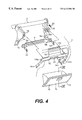
- FIG. 4 is an exploded perspective view showing a portion of the steering support member and a passenger side knee bolster main body.
- FIG. 5 is a front elevation view showing the passenger side knee bolster main body.
- FIG. 6 is a left side elevation view of the passenger side knee bolster main body of FIG. 5 .
- FIG. 7 is a front elevation view of the reinforcement member.
- FIG. 8 is a cross sectional view on line VIII—VIII of FIG. 7 .
- FIG. 9 is a cross sectional view on line IX—IX of FIG. 4 .
- FIG. 10 is an exploded perspective view of a glove compartment according to an embodiment of the present invention.
- FIG. 11 is a perspective view of a knee bolster on the driver side according to a second embodiment of the present invention.
- FIG. 12 is a cross sectional view of a conventional knee bolster structure for an automobile.
- steering support member ( 3 ) is provided behind the dashboard, facing the front seats to support the steering column ( 2 ) within the instrument panel.
- the support member ( 3 ) extends along the width of the car, and is attached to the car chassis by brackets ( 4 ).
- a pair of braces ( 5 ) extend downward from the central portion of the steering support member ( 3 ).
- the two braces ( 5 ) are connected by a stay ( 6 ).
- Member ( 8 ) connects the passenger side bracket ( 4 ) to the passenger side brace ( 5 ), while member ( 7 ) does the same on the driver side. Both members are attached by screws ( 9 ) and ( 10 ), respectively.
- a driver side knee bolster main body ( 11 ) may also be mounted between the steering support member ( 3 ) and member ( 7 ), while a passenger side knee bolster main body ( 12 ) is mounted between the steering support member ( 3 ) and member ( 8 ).
- Members ( 7 ) and ( 8 ) are made of a material like thin steel plate, or other materials of similar properties, and are less rigid that the steering support member ( 3 ) which is made from piping, such as steel tube.
- the knee bolster main body ( 12 ) on the passenger side comprises, as shown in FIGS. 4 and 5, an arch-shaped knee bolster panel ( 14 ) that surrounds the perimeter of the glove compartment, and a lid ( 16 ) to close the glove compartment that houses a reinforcement panel ( 15 ).
- the knee bolster panel ( 14 ) comprises an upper portion ( 14 a ) located in the upper part of the glove compartment ( 13 ), side portions ( 14 b ) located on both the left and right sides of the glove compartment, and a protruding component ( 14 c ) extending up from the central part of the top edge of the upper portion ( 14 a ).
- a reinforcement member ( 17 ) together with the upper portion ( 14 a ), forms a closed cross section structure indicated by X.
- the peripheral edge ( 17 a ) of the reinforcement member 17 can be attached to the back surface of the upper portion ( 14 a ) of the knee bolster, for example, by spot welding.
- This closed cross section structure also called a box structure, is stronger than similar structures formed by flat plates or panels.
- the knee bolster main body ( 12 ) is mounted by screws to the pair of stays ( 18 ) welded to the steering support member. Screw holes ( 17 b ) are provided on both sides of the reinforcement member ( 17 ) of the knee bolster main body ( 12 ), and nuts ( 19 ) are welded to the back surfaces of screw holes ( 17 b ).
- the knee bolster main body ( 12 ) is fastened to the ends of stays ( 18 ) by engaging the screws ( 20 ) in the nuts ( 19 ) and threading the screws ( 20 ) through the screw holes ( 18 a ) provided in the tips of the stays ( 18 ).
- Flanges ( 14 d ) extending from the side portions ( 14 b ) of the knee bolster main body ( 12 ) are mounted with screws in screw holes (not shown in the figures) provided in the flanges ( 8 a ) of member ( 8 ), and are thereby secured to the steering support member ( 3 ).
- the protruding part ( 14 c ) of the knee bolster panel ( 14 ) is secured to the back surface of the instrument panel ( 1 ) by a screw, also not shown in the figure.
- a striker ( 21 ) for the lock of the glove compartment ( 13 ) is located in the lower central part of the knee bolster panel ( 14 ).
- the glove compartment ( 13 ) includes a reinforcement panel ( 15 ) disposed between the lid ( 16 ) and the front surface ( 22 a ) of the glove compartment main body ( 22 ).
- Horizontal and vertical ribs ( 15 a ), ( 15 b ) protrude from the flat plate surface of the reinforcement panel ( 15 ) to increase rigidity of the structure.
- a knee bolster main body ( 11 ) is attached to the tips of the left and right stays ( 23 ) that are, for example, welded to the steering support member ( 3 ) on the driver side.
- the knee bolster body ( 11 ) also includes a closed cross section structure formed by attaching the periphery of the reinforcement member ( 25 ) to the rear top portion of the knee bolster panel ( 24 ). Because of the closed cross section structure, the upper portion of bolster panel ( 24 ) is more rigid than the rest of the panel that is made from plate material. As a result, the energy from large impact loads can be dissipated by deformation of the upper portion, while lower energies can be effectively dissipated by the rest of the bolster main body ( 11 ).
- a wide range of loads acting from different directions can be dissipated by the knee bolster panel ( 14 ) and by the reinforced lid ( 16 ) of the glove compartment ( 13 ).
- the impact energy can be dissipated by deformation of the closed cross section structure (X) formed by the reinforcing member ( 17 ) and the back surface of the upper portion ( 14 a ) of knee bolster panel ( 14 ).
- This closed cross section structure is rigid, and can dissipate the energy from large impact loads effectively.
- the load can be absorbed by the lid ( 16 ) reinforced by the reinforcement panel ( 15 ).
- Lid ( 16 ) is backed on its sides by side portions ( 14 b ) and on its top by upper portion ( 14 a ) of knee bolster panel ( 14 ). Some of the impact energy is thus transmitted from lid reinforcement panel ( 15 ) to the knee bolster panel ( 14 ).
- the lid structure is less rigid than the structure of the knee bolster upper portion, and thus deforms more easily, and can effectively dissipate the energy of smaller impact loads.
- a reinforcement panel ( 25 ) forms a closed cross section together with the upper portion of the knee bolster panel ( 24 ). Large loads can be absorbed by this closed cross section structure of the bolster upper portion, while the remainder of the knee bolster deforms more easily, and is well suited to absorb smaller loads.
- large loads due to knee impacts are absorbed by a two-layer structure comprising the upper portion of the knee bolster panel ( 14 ) and the reinforcement member ( 17 ), arranged to form a closed cross section structure (X).
- Small impact loads can be absorbed by the lower portion of the knee bolster panel ( 14 ) and by the reinforcement ( 15 ) formed in the glove compartment lid.
- the member ( 8 ) supporting the bottom portion of knee bolster panel ( 14 ) is less rigid than the steering support member ( 3 ). This arrangement contributes to a design where the upper portion of the knee bolster is more rigid than the bottom portion, so that each portion is able to deform and absorb the energy of large and small impact loads, respectively.
- the knee bolster has a substantially identical cross section along its dimension extending from left to right in the vehicle, loads acting along the entire horizontal dimension of the bolster can be equally absorbed.
- the rigidity of the knee bolster structure can be easily modified by altering the plate thickness of the knee bolster panel ( 14 ), of the reinforcement member ( 17 ), or of the reinforcement ( 15 ). Thus, it is easy to tailor the structure for specific applications.
- the knee bolster panels ( 14 ), the reinforcement member ( 17 ), the reinforcement ( 15 ), and other structural components of the knee bolster are located within the instrument panel ( 1 ), so that the outer appearance of the dashboard is not sacrificed. This results in cost savings because it is not necessary to paint or otherwise embellish the structure.
- the knee bolster disposed on the driver side of the vehicle exhibits the same advantages as the knee bolster disposed on the passenger seat side, due to the reinforcement panel ( 25 ) forming a closed cross section with the upper portion of knee bolster panel ( 24 ).
- the automobile knee bolster structure exhibits several benefits.
- the knee bolster structure is designed so that its upper portion can effectively absorb the energy of large impact loads, because the top of the knee bolster main body is formed as a closed cross section structure.
- energy generated by small impact loads can also be dissipated effectively by the remaining portions of the knee bolster.
- the structure absorb impact loads that originate from various directions, but loads of different magnitude that are applied to the upper portion and to the bottom portion of the knee bolster can be dissipated by deformation of a structure having a stiffness appropriate to the load.
- the knee bolster main body may be arranged in a position corresponding to the glove compartment, and comprises panels located on the top side and on both lateral sides of the glove compartment, a reinforcement member forming a closed cross section structure with the upper portion of the knee bolster panel, and a reinforcement panel arranged along in the inner surface of the aforementioned glove compartment lid.
Landscapes
- Engineering & Computer Science (AREA)
- Mechanical Engineering (AREA)
- Body Structure For Vehicles (AREA)
- Vehicle Step Arrangements And Article Storage (AREA)
- Instrument Panels (AREA)
Abstract
The present invention is an automobile knee bolster structure capable of absorbing knee impact loads originating from various directions, and also having an upper portion able to absorb greater magnitude loads than the bottom portion of the bolster.
Description
1. Field of the Invention
The present invention relates to an automobile knee bolster that during a collision absorbs the energy of impact between the knees of an occupant and the dashboard, and in particular to a knee bolster that can be used on the driver side or on the passenger side of the dashboard.
2. Description of Related Art
Conventionally, knee bolsters are provided in the lower portion of a vehicle dashboard, facing the legs of passengers sitting in the front seats of an automobile.
In some designs, the lid that covers the glove compartment located in front of the passenger seat is used as part of the knee bolster assembly on the passenger side of the dashboard, as described in Japanese Laid Open Patent Application Hei 4[1992]-63745; and in Japanese Laid Open Patent Application Hei 5[1993]-50889.
FIG. 12 shows one example of a knee bolster structure for the passenger side of a dashboard, wherein the glove compartment lid is used as the knee bolster.
A steering support member (101) is located facing the front seats, and extends along the car width. Member (101) supports the dashboard (102). The glove compartment (103) is located on the passenger side of the dashboard (102), and has a lid (104) containing a reinforcement (105). Knee bolster (106) is supported by the can impact the dashboard approximately at the location of the glove compartment lid (104).
When a conventional knee bolster structure is used, lid (104) deforms to absorb the impact energy from the passenger knees. The impact energy is further carried to the knee bolster (106) located behind lid (104). Thus when the impact has sufficient energy, not only does the lid (104) deform, but the knee bolster (106) also deforms to absorb the load.
With the conventional knee bolster structures, however, the lateral dimension of the lid along the width of the car must correspond to the lateral dimension of the knee bolster (106). Therefore, the length of the reinforcement (105) along the car width becomes large, and the reinforcement's weight increases. One problem of the conventional design is thus excessive weight of the glove compartment assembly (103).
Another problem of the conventional knee bolster is that the top and bottom portions of the knee bolster have the same stiffness, and cannot accommodate different impact forces.
The advantages and purpose of the invention will be set forth in part in the description which follows, and in part will be obvious from the description, or may be learned by practice of the invention. The advantages and purpose of the invention will be realized and attained by means of the elements and combinations particularly pointed out in the appended claims.
The present invention resolves the aforementioned problems. One objective of the invention is thus to provide an automobile knee bolster structure that is light and is capable of absorbing varied loads resulting from a collision with the passenger knees. These loads can be applied to the structure from different directions, and can have different magnitudes depending on whether they are applied to the upper or lower portion of the knee bolster by impacts with the knees of large or small passengers, respectively. According to the present invention, the knee bolster structure is located in the lower portion of an instrument panel, and portions of the knee bolster main body are formed with a closed cross section structure designed for strength and for absorbing the impact from passenger knees.
The knee bolster structure according to the present invention includes a main body that comprises a knee bolster upper panel and a reinforcement member joined to the top portion of the knee bolster upper panel, oriented along the car width. The knee bolster upper panel and the reinforcement member form a closed cross section structure of greater stiffness than the rest of the knee bolster, which is formed from a plate-like structure. The knee bolster main body is located in a position corresponding to the glove compartment, and thus comprises knee bolster side panels located on both sides of the glove compartment, the aforementioned upper panel, and a reinforcement member joined to the top side of the knee bolster upper panel to form the closed cross section structure. A reinforcement arranged as a continuation of the aforementioned knee bolster panels within the lid of the aforementioned glove compartment is also provided.
In a collision, the knees of a larger passenger tend to impact the dashboard with a large force due to the weight of the passenger, and the impact takes place near the upper portion of the dashboard, due to the size of the passenger's legs. Conversely, a smaller, lighter passenger's knees will tend to impact with the lower portion of the dashboard, and with less force.
The present invention compensates for the different impact forces that the upper and lower portions of the bolster have to withstand by using a knee bolster main body that has a reinforced upper portion, including a reinforcement member that together with the upper portion of the knee bolster panel forms a closed cross section structure, also known as a box structure. Consequently, large loads can be absorbed by deformation of the upper portion of the knee bolster main body, to address the situation when a large passenger is involved in a collision.
When a smaller passenger is involved in a collision, a smaller load is applied to the lower part of the knee bolster main body. The lower portion of the knee bolster main body is reinforced by the knee bolster panels and by the reinforcement panel in the glove compartment lid, so that the knee bolster panels and the reinforcement panel deform to absorb the load. These panels are made from a plate-like structure that is less rigid than the closed cross section structure.
The knee bolster main body according to the present invention has an upper portion with a closed cross section structure that provides increased rigidity, and has a lower portion reinforced by the extensive use of reinforcement material such as sheet metal. Thus, the knee bolster main body can dissipate by deformation loads having a wide range of magnitudes, larger on the upper portion, and smaller on the lower portion of the knee bolster.
The accompanying drawings, which are incorporated in and constitute a part of this specification, illustrate embodiments of the invention and together with the description, serve to explain the principles of the invention. In the drawings,
FIG. 1 is an exploded perspective view of one embodiment of the automobile knee bolster structure according to the present invention, used on the passenger side.
FIG. 2 is a cross sectional view along line II—II of FIG. 1.
FIG. 3 is a perspective view showing the steering support member and the knee bolster main body attachment components on the driver and passenger sides according to a second embodiment of the present invention.
FIG. 4 is an exploded perspective view showing a portion of the steering support member and a passenger side knee bolster main body.
FIG. 5 is a front elevation view showing the passenger side knee bolster main body.
FIG. 6 is a left side elevation view of the passenger side knee bolster main body of FIG. 5.
FIG. 7 is a front elevation view of the reinforcement member.
FIG. 8 is a cross sectional view on line VIII—VIII of FIG. 7.
FIG. 9 is a cross sectional view on line IX—IX of FIG. 4.
FIG. 10 is an exploded perspective view of a glove compartment according to an embodiment of the present invention.
FIG. 11 is a perspective view of a knee bolster on the driver side according to a second embodiment of the present invention.
FIG. 12 is a cross sectional view of a conventional knee bolster structure for an automobile.
Reference will now be made in detail to the present preferred embodiments of the invention, examples of which are illustrated in the accompanying drawings.
Wherever possible, the same reference numbers will be used throughout the drawings to refer to the same or like parts.
As shown in FIGS. 1 through 3, steering support member (3) is provided behind the dashboard, facing the front seats to support the steering column (2) within the instrument panel. The support member (3) extends along the width of the car, and is attached to the car chassis by brackets (4).
A pair of braces (5) extend downward from the central portion of the steering support member (3). The two braces (5) are connected by a stay (6). Member (8) connects the passenger side bracket (4) to the passenger side brace (5), while member (7) does the same on the driver side. Both members are attached by screws (9) and (10), respectively. In another embodiment, a driver side knee bolster main body (11) may also be mounted between the steering support member (3) and member (7), while a passenger side knee bolster main body (12) is mounted between the steering support member (3) and member (8). Members (7) and (8) are made of a material like thin steel plate, or other materials of similar properties, and are less rigid that the steering support member (3) which is made from piping, such as steel tube.
The knee bolster main body (12) on the passenger side comprises, as shown in FIGS. 4 and 5, an arch-shaped knee bolster panel (14) that surrounds the perimeter of the glove compartment, and a lid (16) to close the glove compartment that houses a reinforcement panel (15).
The knee bolster panel (14) comprises an upper portion (14 a) located in the upper part of the glove compartment (13), side portions (14 b) located on both the left and right sides of the glove compartment, and a protruding component (14 c) extending up from the central part of the top edge of the upper portion (14 a). As shown in FIGS. 6 and 8, a reinforcement member (17), together with the upper portion (14 a), forms a closed cross section structure indicated by X. The peripheral edge (17 a) of the reinforcement member 17 can be attached to the back surface of the upper portion (14 a) of the knee bolster, for example, by spot welding. This closed cross section structure, also called a box structure, is stronger than similar structures formed by flat plates or panels.
The knee bolster main body (12) is mounted by screws to the pair of stays (18) welded to the steering support member. Screw holes (17 b) are provided on both sides of the reinforcement member (17) of the knee bolster main body (12), and nuts (19) are welded to the back surfaces of screw holes (17 b). The knee bolster main body (12) is fastened to the ends of stays (18) by engaging the screws (20) in the nuts (19) and threading the screws (20) through the screw holes (18 a) provided in the tips of the stays (18). Flanges (14 d) extending from the side portions (14 b) of the knee bolster main body (12) are mounted with screws in screw holes (not shown in the figures) provided in the flanges (8 a) of member (8), and are thereby secured to the steering support member (3). The protruding part (14 c) of the knee bolster panel (14) is secured to the back surface of the instrument panel (1) by a screw, also not shown in the figure. A striker (21) for the lock of the glove compartment (13) is located in the lower central part of the knee bolster panel (14).
As shown in FIG. 9 and FIG. 10, the glove compartment (13) includes a reinforcement panel (15) disposed between the lid (16) and the front surface (22 a) of the glove compartment main body (22). Horizontal and vertical ribs (15 a), (15 b) protrude from the flat plate surface of the reinforcement panel (15) to increase rigidity of the structure.
In the second embodiment shown in FIGS. 3 and 11, a knee bolster main body (11) is attached to the tips of the left and right stays (23) that are, for example, welded to the steering support member (3) on the driver side. The knee bolster body (11) also includes a closed cross section structure formed by attaching the periphery of the reinforcement member (25) to the rear top portion of the knee bolster panel (24). Because of the closed cross section structure, the upper portion of bolster panel (24) is more rigid than the rest of the panel that is made from plate material. As a result, the energy from large impact loads can be dissipated by deformation of the upper portion, while lower energies can be effectively dissipated by the rest of the bolster main body (11).
According to the invention, a wide range of loads acting from different directions can be dissipated by the knee bolster panel (14) and by the reinforced lid (16) of the glove compartment (13). When a load of large magnitude is applied to the upper portion of the knee bolster main body (12), due to impact with the knees of a large passenger, the impact energy can be dissipated by deformation of the closed cross section structure (X) formed by the reinforcing member (17) and the back surface of the upper portion (14 a) of knee bolster panel (14). This closed cross section structure is rigid, and can dissipate the energy from large impact loads effectively.
Conversely, when a small magnitude load is applied to the lower part of the knee bolster main body (12) by impact with the knees of a small passenger, the load can be absorbed by the lid (16) reinforced by the reinforcement panel (15). Lid (16) is backed on its sides by side portions (14 b) and on its top by upper portion (14 a) of knee bolster panel (14). Some of the impact energy is thus transmitted from lid reinforcement panel (15) to the knee bolster panel (14). The lid structure is less rigid than the structure of the knee bolster upper portion, and thus deforms more easily, and can effectively dissipate the energy of smaller impact loads.
On the driver side, energy from knee impacts is absorbed by the knee bolster panel (24). Similarly to the knee bolster on the passenger side, a reinforcement panel (25) forms a closed cross section together with the upper portion of the knee bolster panel (24). Large loads can be absorbed by this closed cross section structure of the bolster upper portion, while the remainder of the knee bolster deforms more easily, and is well suited to absorb smaller loads.
According to the aforementioned embodiment, large loads due to knee impacts are absorbed by a two-layer structure comprising the upper portion of the knee bolster panel (14) and the reinforcement member (17), arranged to form a closed cross section structure (X). Small impact loads can be absorbed by the lower portion of the knee bolster panel (14) and by the reinforcement (15) formed in the glove compartment lid. In addition, the member (8) supporting the bottom portion of knee bolster panel (14) is less rigid than the steering support member (3). This arrangement contributes to a design where the upper portion of the knee bolster is more rigid than the bottom portion, so that each portion is able to deform and absorb the energy of large and small impact loads, respectively.
Moreover, because the knee bolster has a substantially identical cross section along its dimension extending from left to right in the vehicle, loads acting along the entire horizontal dimension of the bolster can be equally absorbed.
The rigidity of the knee bolster structure can be easily modified by altering the plate thickness of the knee bolster panel (14), of the reinforcement member (17), or of the reinforcement (15). Thus, it is easy to tailor the structure for specific applications.
The knee bolster panels (14), the reinforcement member (17), the reinforcement (15), and other structural components of the knee bolster are located within the instrument panel (1), so that the outer appearance of the dashboard is not sacrificed. This results in cost savings because it is not necessary to paint or otherwise embellish the structure.
The knee bolster disposed on the driver side of the vehicle exhibits the same advantages as the knee bolster disposed on the passenger seat side, due to the reinforcement panel (25) forming a closed cross section with the upper portion of knee bolster panel (24).
As described above, the automobile knee bolster structure according to the present invention exhibits several benefits. The knee bolster structure is designed so that its upper portion can effectively absorb the energy of large impact loads, because the top of the knee bolster main body is formed as a closed cross section structure. At the same time, energy generated by small impact loads can also be dissipated effectively by the remaining portions of the knee bolster. Thus, not only can the structure absorb impact loads that originate from various directions, but loads of different magnitude that are applied to the upper portion and to the bottom portion of the knee bolster can be dissipated by deformation of a structure having a stiffness appropriate to the load.
The knee bolster main body may be arranged in a position corresponding to the glove compartment, and comprises panels located on the top side and on both lateral sides of the glove compartment, a reinforcement member forming a closed cross section structure with the upper portion of the knee bolster panel, and a reinforcement panel arranged along in the inner surface of the aforementioned glove compartment lid.
It will be apparent to those skilled in the art that various modifications and variations can be made in the knee bolster structure of the present invention without departing from the scope or spirit of the invention.
Other embodiments of the invention will be apparent to those skilled in the art from consideration of the specification and practice of the invention disclosed herein. It is intended that the specification and examples be considered as exemplary only, with a true scope of the invention being indicated by the following claims.
Claims (9)
1. An automobile knee bolster for absorbing energy from impacts with the knees of an occupant, disposed in a portion of a dashboard corresponding to a glove compartment, and having a main body comprising:
a knee bolster panel including an upper portion, a pair of side portions, and an energy absorbing protruding component, said upper portion arranged in the top of the glove compartment, said side portions arranged on the lateral sides of the glove compartment, said protruding component extending from a central portion of said upper portion, said protruding component being connected to the back of said dashboard;
a reinforcement member attached to the upper portion and oriented along a width of the automobile, wherein the reinforcement member and the upper portion define a closed cross section structure; and
a reinforcement panel arranged behind a lid of the glove compartment cooperating with the main body to dissipate impact energy.
2. The automobile knee bolster according to claim 1, wherein the knee bolster portions arranged on the top and lateral sides of the glove compartment back the lid of the glove compartment when the lid is closed.
3. A knee bolster assembly for absorbing energy from collisions with knees of an occupant in an automobile having a dashboard and a chassis, the knee bolster assembly being disposed in a lower portion of the dashboard, the knee bolster assembly comprising:
a steering support member extending the width of the automobile and located behind the dashboard;
a bracket joining the steering support member to the chassis;
a side brace joined to the steering support member, the side brace being spaced from said bracket;
a thin plate member extending between the side brace and the bracket;
a main body comprising a closed cross section structure and a knee bolster panel, the main body being mounted between the steering support member and the thin plate member, the knee bolster panel having an upper portion, a pair of side portions, and an energy absorbing protruding component, said protruding component extending from a central portion of the upper portion, the protruding component being connected to the back of the dashboard.
4. The knee bolster assembly according to claim 3, wherein the main body includes a reinforcement member oriented along the width of the automobile and attached to the knee bolster panel, the reinforcement member and the knee bolster panel defining the closed cross section structure.
5. The knee bolster assembly according to claim 3, wherein the closed cross section structure is disposed in an upper portion of the main body.
6. The knee bolster assembly according to claim 4, wherein the reinforcement member is attached to the upper portion of the knee bolster panel.
7. The knee bolster assembly according to claim 4, wherein portions of the knee bolster panel are formed of a plate-like structure.
8. The knee bolster assembly according to claim 3, further comprising stays attaching the main body to the steering support member.
9. The knee bolster assembly according to claim 3, wherein the upper portion of the knee bolster main body is attached to the steering support member.
Applications Claiming Priority (2)
| Application Number | Priority Date | Filing Date | Title |
|---|---|---|---|
| JP9-356705 | 1997-12-25 | ||
| JP35670597A JP3838464B2 (en) | 1997-12-25 | 1997-12-25 | Automotive knee bolster structure |
Publications (1)
| Publication Number | Publication Date |
|---|---|
| US6213504B1 true US6213504B1 (en) | 2001-04-10 |
Family
ID=18450371
Family Applications (1)
| Application Number | Title | Priority Date | Filing Date |
|---|---|---|---|
| US09/224,120 Expired - Lifetime US6213504B1 (en) | 1997-12-25 | 1998-12-22 | Automobile knee bolster structure |
Country Status (2)
| Country | Link |
|---|---|
| US (1) | US6213504B1 (en) |
| JP (1) | JP3838464B2 (en) |
Cited By (34)
| Publication number | Priority date | Publication date | Assignee | Title |
|---|---|---|---|---|
| US6431600B1 (en) * | 1999-04-22 | 2002-08-13 | Trw Occupant Restraint Systems Gmbh & Co. Kg | Knee restraint device for vehicles |
| US6447041B1 (en) * | 2000-09-06 | 2002-09-10 | Visteon Global Technologies, Inc. | Integrated HVAC and steering column support structure |
| US6517139B2 (en) * | 2000-12-28 | 2003-02-11 | Suzuki Motor Corporation | Assembly structure of an instrument panel |
| US6554352B2 (en) * | 2001-08-17 | 2003-04-29 | Van-Rob Stampings Inc. | Cross car support structure |
| US6702324B2 (en) * | 2001-05-07 | 2004-03-09 | Izusu Motors Limited | Knee bolster |
| US20040124623A1 (en) * | 2002-12-25 | 2004-07-01 | Yasunobu Yamazaki | Occupant protection apparatus |
| US6786524B2 (en) * | 2002-01-08 | 2004-09-07 | Fuji Jukogyo Kabushiki Kaisha | Glove box for vehicle |
| US20040222669A1 (en) * | 2003-05-06 | 2004-11-11 | Davis Joseph J. | Universal energy absorbing bracket |
| US6837518B2 (en) | 2002-08-23 | 2005-01-04 | L&W Engineering Incorporated | Reinforcement structure for instrument panel |
| US20050071988A1 (en) * | 2003-10-06 | 2005-04-07 | Jeff Owel | Apparatus for fastening weld fasteners to a structure |
| FR2871123A1 (en) * | 2004-06-02 | 2005-12-09 | Renault Sas | ARRANGEMENT FOR PROTECTING THE KNEES OF AN OCCUPANT OF A MOTOR VEHICLE AND DASHBOARD |
| US20060082116A1 (en) * | 2004-10-14 | 2006-04-20 | Riefe Richard K | Knee bolster |
| US20060232055A1 (en) * | 2005-04-15 | 2006-10-19 | Visteon Global Technologies, Inc. | Energy absorbing structure |
| DE10113508B4 (en) * | 2000-03-21 | 2006-11-16 | Lear Corp., Southfield | Energy absorbing device for a knee bolster in a vehicle |
| US20070046010A1 (en) * | 2005-09-01 | 2007-03-01 | Lear Corporation | Plastic bracket countermeasure for door side impact |
| US20070182189A1 (en) * | 2006-02-07 | 2007-08-09 | Penner Benjamin W | Glove box assembly exhibiting knee impact force transferring structure with respect to an associated vehicle dash/instrument panel and reinforcing bar |
| US20080048470A1 (en) * | 2006-08-25 | 2008-02-28 | Gm Global Technology Operations, Inc. | Tubular Instrument Panel Support Structure |
| US20080054681A1 (en) * | 2006-08-31 | 2008-03-06 | Honda Motor Co., Ltd. | Hanger beam assembly |
| US20090020993A1 (en) * | 2007-07-19 | 2009-01-22 | Douglas Michael Cappabianca | Knee bolster assembly |
| US20090045613A1 (en) * | 2007-02-16 | 2009-02-19 | Collins & Aikman Products Co. | Energy management system |
| US20090179411A1 (en) * | 2008-01-11 | 2009-07-16 | Toyota Motor Engineering & Manufacturing North America, Inc. | Instrument panel energy transferring system |
| EP2179910A2 (en) | 2008-10-27 | 2010-04-28 | Honda Motor Co., Ltd | Method of making a composite component and component |
| US20100219653A1 (en) * | 2009-02-27 | 2010-09-02 | Nissan Technical Center North America, Inc. | Vehicle interior assembly |
| US20110084512A1 (en) * | 2008-10-07 | 2011-04-14 | Matthew Lee Taracko | Glove box knee bolster assembly for vehicle and method of manufacturing |
| US20110187145A1 (en) * | 2010-01-29 | 2011-08-04 | Suzuki Motor Corporation | Instrument panel |
| US20110221224A1 (en) * | 2010-03-10 | 2011-09-15 | Ford Global Technologies, Llc | Equipment mounting module for instrument panel |
| US20120001455A1 (en) * | 2010-07-02 | 2012-01-05 | Honda Motor Co., Ltd. | Frontal structure of vehicle |
| US8491037B2 (en) * | 2011-08-09 | 2013-07-23 | Ford Global Technologies, Llc | Extend and breakaway bracket for glove box |
| GB2515630A (en) * | 2014-04-30 | 2014-12-31 | Daimler Ag | Arrangement of a glove box assembly on a cockpit cross member of a passenger vehicle |
| US9457755B2 (en) * | 2015-01-09 | 2016-10-04 | Toyota Motor Engineering & Manufacturing North America, Inc. | One piece instrument panel with molded upper bin |
| US9604589B1 (en) * | 2015-10-29 | 2017-03-28 | Ford Global Technologies, Llc | Polymeric bracket for instrumental panel side passenger knee protection |
| US20180126940A1 (en) * | 2016-11-04 | 2018-05-10 | Magnesium Products of America Inc. | Glove box rail with integrated airbag support |
| US20220266921A1 (en) * | 2021-02-23 | 2022-08-25 | Ford Global Technologies, Llc | Vehicle instrument panel assembly |
| DE102019104330B4 (en) * | 2018-02-28 | 2025-07-10 | Suzuki Motor Corporation | Structure of an instrument panel |
Families Citing this family (3)
| Publication number | Priority date | Publication date | Assignee | Title |
|---|---|---|---|---|
| JP3767497B2 (en) | 2002-03-01 | 2006-04-19 | トヨタ自動車株式会社 | Vehicle occupant knee protection device |
| KR20030093642A (en) * | 2002-06-04 | 2003-12-11 | 기아자동차주식회사 | Reinforcing bracket for improving strength of front door of vehicle |
| KR100710671B1 (en) * | 2005-12-09 | 2007-04-24 | 현대모비스 주식회사 | Nibolster for glove box of car |
Citations (15)
| Publication number | Priority date | Publication date | Assignee | Title |
|---|---|---|---|---|
| US4400011A (en) * | 1980-03-31 | 1983-08-23 | Nissan Motor Co., Ltd. | Vehicle body construction |
| US4709943A (en) * | 1985-07-17 | 1987-12-01 | Mazda Motor Corporation | Knee protector structure for vehicle |
| US4893834A (en) * | 1987-06-18 | 1990-01-16 | Honda Giken Kogyo Kabushiki Kaisha | Automotive knee bolster |
| US4946192A (en) * | 1987-12-25 | 1990-08-07 | Nissan Motor Company, Limited | Knee protector |
| US4978136A (en) * | 1988-12-19 | 1990-12-18 | Mazda Motor Corporation | Automotive knee protector |
| JPH0463745A (en) | 1990-07-04 | 1992-02-28 | Mazda Motor Corp | Glove box device for vehicle |
| JPH0550889A (en) | 1991-08-20 | 1993-03-02 | Mazda Motor Corp | Knee protector structure for automobile |
| US5413379A (en) * | 1993-09-16 | 1995-05-09 | Honda Giken Kogyo Kabushiki Kaisha | Knee bolster structure |
| US5518270A (en) * | 1994-03-30 | 1996-05-21 | Nissan Motor Co., Ltd. | Knee protector device for vehicle |
| JPH08164811A (en) | 1994-12-14 | 1996-06-25 | Suzuki Motor Corp | Knee bolster structure |
| US5676216A (en) * | 1994-04-14 | 1997-10-14 | Ford Global Technologies, Inc. | Structural two-piece composite instrument panel cross-beam with integrated air distribution system |
| US5718453A (en) * | 1995-12-23 | 1998-02-17 | Mercedes-Benz Ag | Knee protection device having a load distributor for a motor vehicle |
| US5931520A (en) * | 1997-12-19 | 1999-08-03 | Aluminum Company Of America | Light weight instrument panel reinforcement structure |
| US5934733A (en) * | 1997-12-19 | 1999-08-10 | General Motors Corporation | Extruded instrument panel structure |
| US5951045A (en) * | 1997-03-26 | 1999-09-14 | A B Volvo | Knee protection system for a vehicle |
-
1997
- 1997-12-25 JP JP35670597A patent/JP3838464B2/en not_active Expired - Fee Related
-
1998
- 1998-12-22 US US09/224,120 patent/US6213504B1/en not_active Expired - Lifetime
Patent Citations (15)
| Publication number | Priority date | Publication date | Assignee | Title |
|---|---|---|---|---|
| US4400011A (en) * | 1980-03-31 | 1983-08-23 | Nissan Motor Co., Ltd. | Vehicle body construction |
| US4709943A (en) * | 1985-07-17 | 1987-12-01 | Mazda Motor Corporation | Knee protector structure for vehicle |
| US4893834A (en) * | 1987-06-18 | 1990-01-16 | Honda Giken Kogyo Kabushiki Kaisha | Automotive knee bolster |
| US4946192A (en) * | 1987-12-25 | 1990-08-07 | Nissan Motor Company, Limited | Knee protector |
| US4978136A (en) * | 1988-12-19 | 1990-12-18 | Mazda Motor Corporation | Automotive knee protector |
| JPH0463745A (en) | 1990-07-04 | 1992-02-28 | Mazda Motor Corp | Glove box device for vehicle |
| JPH0550889A (en) | 1991-08-20 | 1993-03-02 | Mazda Motor Corp | Knee protector structure for automobile |
| US5413379A (en) * | 1993-09-16 | 1995-05-09 | Honda Giken Kogyo Kabushiki Kaisha | Knee bolster structure |
| US5518270A (en) * | 1994-03-30 | 1996-05-21 | Nissan Motor Co., Ltd. | Knee protector device for vehicle |
| US5676216A (en) * | 1994-04-14 | 1997-10-14 | Ford Global Technologies, Inc. | Structural two-piece composite instrument panel cross-beam with integrated air distribution system |
| JPH08164811A (en) | 1994-12-14 | 1996-06-25 | Suzuki Motor Corp | Knee bolster structure |
| US5718453A (en) * | 1995-12-23 | 1998-02-17 | Mercedes-Benz Ag | Knee protection device having a load distributor for a motor vehicle |
| US5951045A (en) * | 1997-03-26 | 1999-09-14 | A B Volvo | Knee protection system for a vehicle |
| US5931520A (en) * | 1997-12-19 | 1999-08-03 | Aluminum Company Of America | Light weight instrument panel reinforcement structure |
| US5934733A (en) * | 1997-12-19 | 1999-08-10 | General Motors Corporation | Extruded instrument panel structure |
Cited By (61)
| Publication number | Priority date | Publication date | Assignee | Title |
|---|---|---|---|---|
| US6431600B1 (en) * | 1999-04-22 | 2002-08-13 | Trw Occupant Restraint Systems Gmbh & Co. Kg | Knee restraint device for vehicles |
| DE10113508B4 (en) * | 2000-03-21 | 2006-11-16 | Lear Corp., Southfield | Energy absorbing device for a knee bolster in a vehicle |
| US6447041B1 (en) * | 2000-09-06 | 2002-09-10 | Visteon Global Technologies, Inc. | Integrated HVAC and steering column support structure |
| US6517139B2 (en) * | 2000-12-28 | 2003-02-11 | Suzuki Motor Corporation | Assembly structure of an instrument panel |
| US6702324B2 (en) * | 2001-05-07 | 2004-03-09 | Izusu Motors Limited | Knee bolster |
| US6554352B2 (en) * | 2001-08-17 | 2003-04-29 | Van-Rob Stampings Inc. | Cross car support structure |
| US6786524B2 (en) * | 2002-01-08 | 2004-09-07 | Fuji Jukogyo Kabushiki Kaisha | Glove box for vehicle |
| US6837518B2 (en) | 2002-08-23 | 2005-01-04 | L&W Engineering Incorporated | Reinforcement structure for instrument panel |
| US20040124623A1 (en) * | 2002-12-25 | 2004-07-01 | Yasunobu Yamazaki | Occupant protection apparatus |
| US7311327B2 (en) * | 2002-12-25 | 2007-12-25 | Mitsubishi Jidosha Kogyo Kabushiki Kaisha | Occupant protection apparatus |
| US20040222669A1 (en) * | 2003-05-06 | 2004-11-11 | Davis Joseph J. | Universal energy absorbing bracket |
| US6921128B2 (en) * | 2003-05-06 | 2005-07-26 | Lear Corporation | Universal energy absorbing bracket |
| US20050071988A1 (en) * | 2003-10-06 | 2005-04-07 | Jeff Owel | Apparatus for fastening weld fasteners to a structure |
| FR2871123A1 (en) * | 2004-06-02 | 2005-12-09 | Renault Sas | ARRANGEMENT FOR PROTECTING THE KNEES OF AN OCCUPANT OF A MOTOR VEHICLE AND DASHBOARD |
| WO2005123466A1 (en) * | 2004-06-02 | 2005-12-29 | Renault S.A.S. | Arrangement for protecting a motor vehicle passenger's knees and instrument panel therefor |
| CN100478222C (en) * | 2004-06-02 | 2009-04-15 | 雷诺两合公司 | Arrangement for protecting a motor vehicle passenger's knees and instrument panel therefor |
| US20060082116A1 (en) * | 2004-10-14 | 2006-04-20 | Riefe Richard K | Knee bolster |
| US7331606B2 (en) | 2004-10-14 | 2008-02-19 | Delphi Technologies, Inc. | Knee bolster |
| US20060232055A1 (en) * | 2005-04-15 | 2006-10-19 | Visteon Global Technologies, Inc. | Energy absorbing structure |
| US20070046010A1 (en) * | 2005-09-01 | 2007-03-01 | Lear Corporation | Plastic bracket countermeasure for door side impact |
| US7708313B2 (en) | 2005-09-01 | 2010-05-04 | International Automotive Components Group North America, Inc. | Plastic basket countermeasure for door side impact |
| US20070182189A1 (en) * | 2006-02-07 | 2007-08-09 | Penner Benjamin W | Glove box assembly exhibiting knee impact force transferring structure with respect to an associated vehicle dash/instrument panel and reinforcing bar |
| US7484792B2 (en) * | 2006-02-07 | 2009-02-03 | Toyota Motor Engineering & Manufacturing North America, Inc. | Glove box assembly exhibiting knee impact force transferring structure with respect to an associated vehicle dash/instrument panel and reinforcing bar |
| US7503622B2 (en) * | 2006-08-25 | 2009-03-17 | Gm Global Technology Operations, Inc. | Tubular instrument panel support structure |
| US20080048470A1 (en) * | 2006-08-25 | 2008-02-28 | Gm Global Technology Operations, Inc. | Tubular Instrument Panel Support Structure |
| US7367613B2 (en) * | 2006-08-31 | 2008-05-06 | Honda Motor Co., Ltd. | Hanger beam assembly |
| US7374232B2 (en) * | 2006-08-31 | 2008-05-20 | Honda Motor Co., Ltd. | Hanger beam assembly |
| US7377578B2 (en) * | 2006-08-31 | 2008-05-27 | Honda Motor Co., Ltd. | Hanger beam assembly |
| US20080054680A1 (en) * | 2006-08-31 | 2008-03-06 | Honda Motor Co., Ltd. | Hanger beam assembly |
| US20080054682A1 (en) * | 2006-08-31 | 2008-03-06 | Honda Motor Co., Ltd. | Hanger beam assembly |
| US20080054681A1 (en) * | 2006-08-31 | 2008-03-06 | Honda Motor Co., Ltd. | Hanger beam assembly |
| US20090045613A1 (en) * | 2007-02-16 | 2009-02-19 | Collins & Aikman Products Co. | Energy management system |
| US20090020993A1 (en) * | 2007-07-19 | 2009-01-22 | Douglas Michael Cappabianca | Knee bolster assembly |
| US7735865B2 (en) | 2007-07-19 | 2010-06-15 | Visteon Global Technologies, Inc. | Knee bolster assembly |
| US7703829B2 (en) | 2008-01-11 | 2010-04-27 | Toyota Motor Engineering & Manufacturing North America, Inc. | Instrument panel energy transferring system |
| US20090179411A1 (en) * | 2008-01-11 | 2009-07-16 | Toyota Motor Engineering & Manufacturing North America, Inc. | Instrument panel energy transferring system |
| US8118348B2 (en) * | 2008-10-07 | 2012-02-21 | Honda Motor Co., Ltd. | Glove box knee bolster assembly for vehicle and method of manufacturing |
| US20110084512A1 (en) * | 2008-10-07 | 2011-04-14 | Matthew Lee Taracko | Glove box knee bolster assembly for vehicle and method of manufacturing |
| EP2179910A2 (en) | 2008-10-27 | 2010-04-28 | Honda Motor Co., Ltd | Method of making a composite component and component |
| US9233415B2 (en) | 2008-10-27 | 2016-01-12 | Honda Motor Co., Ltd. | Method of making a composite component and apparatus |
| EP2179910A3 (en) * | 2008-10-27 | 2010-06-02 | Honda Motor Co., Ltd | Method of making a composite component and component |
| US8424207B2 (en) | 2008-10-27 | 2013-04-23 | Honda Motor Co., Ltd. | Method of making a composite component and apparatus |
| US20100101090A1 (en) * | 2008-10-27 | 2010-04-29 | Takashi Nakano | Method of Making a Composite Component and Apparatus |
| CN101722990B (en) * | 2008-10-27 | 2012-08-29 | 本田技研工业株式会社 | Composite component manufacturing method and device |
| US7992915B2 (en) * | 2009-02-27 | 2011-08-09 | Nissan North America, Inc. | Vehicle interior assembly |
| US20100219653A1 (en) * | 2009-02-27 | 2010-09-02 | Nissan Technical Center North America, Inc. | Vehicle interior assembly |
| US8714614B2 (en) * | 2010-01-29 | 2014-05-06 | Suzuki Motor Corporation | Instrument panel |
| US20110187145A1 (en) * | 2010-01-29 | 2011-08-04 | Suzuki Motor Corporation | Instrument panel |
| US20110221224A1 (en) * | 2010-03-10 | 2011-09-15 | Ford Global Technologies, Llc | Equipment mounting module for instrument panel |
| US8272675B2 (en) | 2010-03-10 | 2012-09-25 | Ford Global Technologies, Llc | Equipment mounting module for instrument panel |
| US8480164B2 (en) * | 2010-07-02 | 2013-07-09 | Honda Motor Co., Ltd. | Frontal structure of vehicle |
| US20120001455A1 (en) * | 2010-07-02 | 2012-01-05 | Honda Motor Co., Ltd. | Frontal structure of vehicle |
| US8491037B2 (en) * | 2011-08-09 | 2013-07-23 | Ford Global Technologies, Llc | Extend and breakaway bracket for glove box |
| GB2515630A (en) * | 2014-04-30 | 2014-12-31 | Daimler Ag | Arrangement of a glove box assembly on a cockpit cross member of a passenger vehicle |
| US9457755B2 (en) * | 2015-01-09 | 2016-10-04 | Toyota Motor Engineering & Manufacturing North America, Inc. | One piece instrument panel with molded upper bin |
| US9604589B1 (en) * | 2015-10-29 | 2017-03-28 | Ford Global Technologies, Llc | Polymeric bracket for instrumental panel side passenger knee protection |
| US20180126940A1 (en) * | 2016-11-04 | 2018-05-10 | Magnesium Products of America Inc. | Glove box rail with integrated airbag support |
| US10457240B2 (en) * | 2016-11-04 | 2019-10-29 | Magnesium Products Of America | Glove box rail with integrated airbag support |
| DE102019104330B4 (en) * | 2018-02-28 | 2025-07-10 | Suzuki Motor Corporation | Structure of an instrument panel |
| US20220266921A1 (en) * | 2021-02-23 | 2022-08-25 | Ford Global Technologies, Llc | Vehicle instrument panel assembly |
| US11603140B2 (en) * | 2021-02-23 | 2023-03-14 | Ford Global Technologies, Llc | Vehicle instrument panel assembly |
Also Published As
| Publication number | Publication date |
|---|---|
| JP3838464B2 (en) | 2006-10-25 |
| JPH11180238A (en) | 1999-07-06 |
Similar Documents
| Publication | Publication Date | Title |
|---|---|---|
| US6213504B1 (en) | Automobile knee bolster structure | |
| US7735865B2 (en) | Knee bolster assembly | |
| US5868457A (en) | Structural member of vehicle body | |
| US6761412B1 (en) | Backrest construction | |
| US7997548B2 (en) | Vehicle shifter mounting bracket system and method | |
| US4421343A (en) | Knee panel for front seat and knee panel mounting structure for vehicle | |
| JP3644479B2 (en) | Seat mounting structure | |
| JP3739976B2 (en) | Auto body structure | |
| JPH0930449A (en) | Vehicle dash lower panel peripheral structure | |
| JP3312412B2 (en) | Attachment structure of the bumper reinforce of the car to the body side member | |
| JP3001173B2 (en) | Car | |
| JP2002308151A (en) | Cab floor structure for cab-over type vehicle | |
| JP2014083955A (en) | Vehicle body rear part structure of vehicle | |
| JP5010142B2 (en) | Knee protector structure for vehicles | |
| JP2004322719A (en) | Vehicle front structure | |
| JP2007513000A (en) | Car seats and cars equipped with the same | |
| JP2600435Y2 (en) | Car knee collision protection device | |
| JP3569601B2 (en) | Vehicle door structure | |
| JP3507013B2 (en) | Tether anchor mounting structure for child seat | |
| JP2002316666A (en) | Body front structure | |
| KR200170963Y1 (en) | Connection structure reinforcement between rear wheel house inner panel and rear skirt panel of automobile | |
| JPH11180237A (en) | Knee bolster structure of a car | |
| JP2596887Y2 (en) | Fixed part structure of anchor plate | |
| WO2025181851A1 (en) | Grip structure for vehicle | |
| KR200192389Y1 (en) | Body Center Filler for Passenger Vehicles |
Legal Events
| Date | Code | Title | Description |
|---|---|---|---|
| AS | Assignment |
Owner name: SUZUKI MOTOR CORPORATION, JAPAN Free format text: ASSIGNMENT OF ASSIGNORS INTEREST;ASSIGNORS:ISANO, MAKOTO;FUJIMURA, TAKANOBU;REEL/FRAME:009755/0669 Effective date: 19981218 |
|
| FEPP | Fee payment procedure |
Free format text: PAYOR NUMBER ASSIGNED (ORIGINAL EVENT CODE: ASPN); ENTITY STATUS OF PATENT OWNER: LARGE ENTITY |
|
| STCF | Information on status: patent grant |
Free format text: PATENTED CASE |
|
| FPAY | Fee payment |
Year of fee payment: 4 |
|
| FPAY | Fee payment |
Year of fee payment: 8 |
|
| FPAY | Fee payment |
Year of fee payment: 12 |