US6203662B1 - Method for the continuous cooking of pulp in a digester system having a top separator - Google Patents
Method for the continuous cooking of pulp in a digester system having a top separator Download PDFInfo
- Publication number
- US6203662B1 US6203662B1 US09/024,464 US2446498A US6203662B1 US 6203662 B1 US6203662 B1 US 6203662B1 US 2446498 A US2446498 A US 2446498A US 6203662 B1 US6203662 B1 US 6203662B1
- Authority
- US
- United States
- Prior art keywords
- liquor
- cooking
- zone
- impregnation
- vessel
- Prior art date
- Legal status (The legal status is an assumption and is not a legal conclusion. Google has not performed a legal analysis and makes no representation as to the accuracy of the status listed.)
- Expired - Lifetime
Links
Images


Classifications
-
- D—TEXTILES; PAPER
- D21—PAPER-MAKING; PRODUCTION OF CELLULOSE
- D21C—PRODUCTION OF CELLULOSE BY REMOVING NON-CELLULOSE SUBSTANCES FROM CELLULOSE-CONTAINING MATERIALS; REGENERATION OF PULPING LIQUORS; APPARATUS THEREFOR
- D21C1/00—Pretreatment of the finely-divided materials before digesting
-
- D—TEXTILES; PAPER
- D21—PAPER-MAKING; PRODUCTION OF CELLULOSE
- D21C—PRODUCTION OF CELLULOSE BY REMOVING NON-CELLULOSE SUBSTANCES FROM CELLULOSE-CONTAINING MATERIALS; REGENERATION OF PULPING LIQUORS; APPARATUS THEREFOR
- D21C7/00—Digesters
- D21C7/06—Feeding devices
-
- D—TEXTILES; PAPER
- D21—PAPER-MAKING; PRODUCTION OF CELLULOSE
- D21C—PRODUCTION OF CELLULOSE BY REMOVING NON-CELLULOSE SUBSTANCES FROM CELLULOSE-CONTAINING MATERIALS; REGENERATION OF PULPING LIQUORS; APPARATUS THEREFOR
- D21C7/00—Digesters
- D21C7/14—Means for circulating the lye
Definitions
- the present invention relates to a novel method for producing pulp, preferably sulphate cellulose, with the aid of a continuous cooking process.
- ITCTM is mainly based on using almost the same temperature (relatively low compared to prior art) in all cooking zones in combination with moderate alkaline levels.
- the ITCTM-concept does not merely relate to the equalization of temperatures between different cooking zones, but a considerable contribution of the ITCTM-concept relates to enabling an equalized alkaline profile also in the lower part of the counter-current cooking zone.
- impregnation with the aid of black liquor can improve the strength properties of the fibers in the pulp produced.
- the aim of the impregnation is, in the first place, to thoroughly soak each chip so that it becomes susceptible, by penetration and diffusion, to the active cooking chemicals which, in the context of sulphate cellulose, principally consist of sodium hydroxide and sodium sulphide.
- FIG. 1 is a schematic flow diagram of a preferred first embodiment of a digester system according to the present invention
- FIG. 2 is a cross-sectional view of a preferred top separator to be used in a steam/liquid-phase digester according to the present invention
- FIG. 3 is a schematic flow diagram of a preferred second embodiment of a digester system according to the present invention.
- FIG. 4 is a schematic flow diagram of a preferred third embodiment of a digester system according to the present invention.
- FIG. 5 is a schematic flow diagram of a preferred fourth embodiment of a digester system according to the present invention.
- FIG. 6 is a cross-sectional view of a preferred top separator to be used in an hydraulic digester according to the present invention.
- FIG. 7 is a schematic flow diagram of a preferred fifth embodiment of a digester system according to the present invention.
- FIG. 8 is a schematic flow diagram of a preferred sixth embodiment of a digester system according to the present invention.
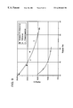
- FIG. 9 shows a diagram presenting the advantages related to the H-factor when using the invention.
- FIG. 10 shows which conditions were used in the laboratory for one of the ITC-references and one of the cooks according to the invention (so called modified ITC);
- FIG. 11 shows test data related to peroxide consumption and brightness for the present compact method compared to a conventional process
- FIG. 12 shows test data related to tensile index and tear index for the present compact method compared to a conventional process
- FIG. 13 shows test data related to tensile index and tear index for the present compact method compared to a conventional process
- FIG. 14 shows test data related to Cl charge and brightness for the present compact method compared to a conventional process
- FIG. 15 shows test data related to brightness and viscosity for the present compact method compared to a conventional process.
- FIG. 1 shows a preferred embodiment of a two vessel steam/liquid-phase digester for producing chemical pulp according to the invention.
- the main components of the digesting system consist of an impregnation vessel 1 and a steam/liquid-phase digester 6 .
- the impregnation vessel 1 which normally is totally liquid filled has a feeding-in device 2 disposed at the top.
- This feeding-in device may be of a conventional type, i.e., a top separator with a screw-feed device that feeds the chips in a downward direction at the same time as transport liquid is drawn off.
- the impregnation vessel may have a feeding-out device 3 comprising a bottom scraper.
- a conduit 17 for adding hot black liquor is attached to the impregnation vessel 1 .
- the black liquor is preferably supplied at the top of the impregnation vessel.
- no draw-off screen is located on the impregnation vessel. However, such draw-off may be provided, if so desired.
- the chips are fed from a chip bin 20 A, through a steaming vessel 20 B and a chip chute 20 C. Finally, a feeding device, preferably a high-pressure feeder 19 , feeds the chips via a conduit 18 to the top of the impregnation vessel 1 .
- the feeder 19 is arranged to a chute, and is connected to necessary liquid circulations and replenishment.
- a conduit 21 for transporting chips extends from the bottom of the impregnation vessel 1 up to the top 5 of the digester 6 having a steam space, wherein the liquid level being indicated by means of a broken line.
- a supply line for steam at the top provides for heating of the steam space.
- the conduit 21 opens out at the bottom of a top separator 7 which feeds by means of a screw in an upwardly moving direction.
- the screen of the separator is used to draw off the liquid D (which is then returned in the return line 15 ) together with which the chips are transported up to the top.
- An important feature of the present invention is that a substantial portion of all the spent liquor that is conveyed to a recovery unit 16 is taken from the free liquid (D) in the return line 15 via a conduit 33 .
- annular ring 23 At the upper edge of the screen (over which edge the chips tumble out), there is arranged an integrated annular ring 23 (best seen in FIG. 2 ).
- the annular ring 23 is connected to a conduit 24 which (preferably via a heat-exchanger 13 A) leads to a white-liquor container (not shown).
- a screen girdle section 8 is arranged in conjunction with a step-out approximately in the middle of the digester 6 . Draw-off from this screen girdle section 8 can be conducted directly via conduit 17 to the impregnation vessel 1 .
- the black liquor is drawn off via a conduit 28 to a first flash cyclone 9 .
- the first flash cyclone may be in operative engagement with the heat exchanger 13 A to provide steam to the heat exchanger.
- a feeding-out device including one scraping element 22 .
- a “cold-blow” process is carried out so that the temperature of the pulp is cooled down at the bottom of the digester with the aid of relatively cold (preferably 70-80° C.) liquid (washing liquid) which is added by means of the scraping element 22 and/or other liquid-adding devices 25 (such as annular pipes) at the bottom of the digester, and then subsequently conducted upwards in counter-current.
- relatively cold (preferably 70-80° C.) liquid (washing liquid) which is added by means of the scraping element 22 and/or other liquid-adding devices 25 (such as annular pipes) at the bottom of the digester, and then subsequently conducted upwards in counter-current.
- This lower circulation consists of a screen girdle section 12 (in the shown embodiment consisting of three rows) which is disposed at a sufficient height above the lower liquid-addition point 22 and/or 25 to permit the attainment of a desired flow from the latter liquid-addition point towards the screen section 12 .
- the draw-off from the screen girdles 12 is recirculated (for displacing black liquor in counter-current to the draw-off screen 8 ) into the digester with the aid of a central pipe 14 (or alternately a stand pipe from the bottom of the digester) which opens out approximately on a level with the screen girdle section 12 .
- a heat exchanger 120 for temperature regulation (increasing the temperature of the re-introduced liquid) and a pump are also located in the conduit 11 which connects the screen girdle 12 with the central pipe 14 .
- the recirculation loop 11 is also connected via a branch conduit 27 to the white liquor supply so that fresh alkali can be supplied and, in the form of counter-current cooking, further reducing the kappa number.
- the digester construction described is notable for the lack of a plurality of central pipes arranged from above and hanging downwards, as well as of feed pipes connected to them and of other necessary parts for the circulations.
- a preferred operation according to the invention may function as follows.
- the chips are fed in into the chip bin 20 A, subsequently steamed 20 B and thereafter forwarded into the chute 20 C.
- the high-pressure feeder 19 (which is supplied with a minor amount of white liquor, such as 5% of the total amount, in order to lubricate the feeder) with the aid of which the chips are fed into the conduit 18 together with the transport liquid.
- the slurry of the chips and the liquid that is fed to the top of the impregnation vessel in this way may have a temperature of about 110-120° C. on entry to the impregnation vessel (excluding recirculated transport liquor).
- the latter In addition to the actual fibers in the wood, the latter also conveys its own moisture (the wood moisture), which normally constitutes about 50% of the original weight, to the impregnation vessel. Over and above this, some condense is present from the steaming, i.e., at least a part of the steam (principally low-pressure steam) which was supplied to the steaming vessel 20 B is cooled down to such a low level that it condenses and is then recovered as liquid together with the wood and the transport liquid.
- the wood moisture normally constitutes about 50% of the original weight
- the impregnation vessel 1 At the top of the impregnation vessel 1 , there is a screw feeder 2 that pushes chips from above and downwards into the impregnation vessel. No liquid is preferably recirculated within the impregnation vessel. Instead, liquid from a point that is after the first flash 9 is supplied. If desired, however, such recirculation may be provided in the impregnation vessel.
- the chips which are fed out from the bottom of the top screen 2 then move slowly downwards in a plug flow through the impregnation vessel 1 in a liquid/wood ratio between 2/1-10/1 preferably between 3/1-8/1, more preferred of about 4/1-6/1.
- Hot black liquor which is drawn off from the first flash 9 , is added, via conduit 17 , to the top of the impregnation vessel 1 .
- the high temperature of the black liquor (100-160° C.), preferably exceeding 130° C., more preferred between 130-160° C., ensures rapid heating of the chips.
- the relatively high pH, exceeding pH 10 of the black liquor neutralizes acidic groups in the wood and also any acidic condensate accompanying the chips, thereby, i.e., counteracting the formation of encrustation, so-called scaling.
- the black liquor supplied into the impregnation vessel has a high content of rest alkali, (EA as NaOH), at least 13 g/l, preferably about or above 16 g/l and more preferred between 13-30 g/l at the top of the impregnation vessel.
- This alkali mainly comes from the black liquor due to the high amount of alkali in the concurrent zone B of the digester.
- the strength properties of the fibers are positively affected by the impregnation because the high amount of sulphide.
- the major portion of black liquor is directly (or via one flash) fed to the impregnation vessel 1 .
- a minor amount of the black liquor may be used for transferring the chips from the HP-feeder to the inlet of the impregnation vessel.
- the two flows of black liquor are preferably used to regulate the temperature within the impregnation zone A.
- the temperature is less than 140° C.
- the temperature of the black liquor may also be between about 140° C. and about 160° C.
- the total supply of black liquor to the impregnation vessel exceeds 80% of the amount drawn off from the draw-off strainers 8 , preferably more than 90% and optimally about 100% of the total flow, which normally is about 8-12 m 3 /ADT.
- the chips which have been thoroughly impregnated and partially delignified in the impregnation vessel, are fed to the top of the digester 6 and conveyed into the upwardly-feeding top separator 7 .
- the chips are thus fed upwardly through the screen, meanwhile free transport liquid is withdrawn outwardly through the screen and finally the chips fall out over the edge of the screen down through the steam space.
- the chips pieces are drained with cooking liquor which is supplied by means of the top separator 7 .
- the white liquor is preferably heated by the heat exchanger 13 A that preferably is supplied with heat steam from flash tank 9 .
- the free transport liquid is conveyed via the return line 15 back to the bottom of the impregnation vessel 1 .
- the free transport liquid contains spent impregnation liquor.
- at least 4 m 3 /ADT; more preferably at least about 5 m 3 /ADT of spent impregnation liquor is conducted via the conduit 33 to the recovery unit 16 .
- This spent impregnation liquor has an effective alkaline value (measured as NaOH) that is below 10 grams/liter. More preferred, the effective alkaline value of the spent impregnation liquor is below 8 grams/liter.
- the quantity of white liquor that is added at the top of the digester 6 depends on how much white liquor possibly is added else where, but the total amount corresponds to the quantity of white liquor that is required for achieving desired delignification of the wood.
- a major part of the white liquor is added here, i.e., more than 60%, which also improves the diffusion velocity, since it increases in relation to the concentration difference (chip-surrounding liquid).
- the thoroughly impregnated chips rapidly assimilate the active cooking chemicals by diffusion, since the concentration of alkali (EA as NaOH) is relatively high, at least 20 g/l, preferably between 30 g/l and 50 g/l and more preferred about 40 g/l.
- the chips then move down into the concurrent cooking zone B and through the digester 6 at a relatively low cooking temperature, i.e., between about 130-160° C., preferably about 140-150° C.
- a relatively low cooking temperature i.e., between about 130-160° C., preferably about 140-150° C.
- the major part of the delignification takes place in the first concurrent cooking zone B.
- the retention time in this first cooking zone should be at least 20 minutes, preferably at least 30 minutes and more preferred at least 40 minutes.
- the liquid-wood ratio should be at lest 2/1 and should be below 7/1, preferably in the range of 3/1-5.5/1, more preferred between 3.5/1 and 5/1. (The liquid wood-ratio in the counter-current cooking zone C should be about the same as in the concurrent cooking zone B.)
- the cooking liquid mingled with released lignin, etc., is drawn off at the draw-off screen 8 into the conduit 28 .
- liquid finally is also supplied in the lower part of the digester which moves in counter-current. It can be described as the central pipe 14 displacing it from the wood upwards towards the draw-off screen 8 . This results, consequently, in the delignification being prolonged in the digester 6 .
- the temperature in the lower counter-current cooking zone C is preferably higher than the temperature in the concurrent cooking zone B, i.e., preferably exceeding 140° C., preferably about 145-165° C., in order to dissolve remaining lignin.
- the alkali content in the lowermost part of the counter-current cooking zone should preferably be lower than in the beginning of the concurrent zone, above 5 g/l, but below 40 g/l. Preferably less than 30 g/l and more preferred between 10-20 g/l. In the preferred case, the aim is to have a temperature difference of about 10° C. between the cooking zones.
- the lower circulation 11 , 12 , 13 , 14 is charged with about 5-20%, preferably 10-15%, white liquor.
- the temperature of the liquid which is recirculated via the central pipe 14 that is regulated with the aid of a heat exchanger 120 so that the desired cooking temperature is obtained at the lowermost part of the counter-current cooking zone C.
- the “cold-blow” process is used so that the temperature of the pulp in the outlet conduit 26 is less than 100° C. Accordingly, washing liquid having a low temperature, preferably about 70-80° C., is added by using the scraping element and an outer annular conduit 25 arranged at the bottom of the digester 6 . This liquid consequently displaces the boiling hot liquor in the pulp upwards in counter-current and thereby imparts a temperature to the remaining pulp which can be cold-blown, i.e., depressurized and disintegrated without any real loss of strength.
- FIG. 2 there is shown a preferred embodiment of a separator to be used in connection with a steam/vapor phase digester, as described in FIG. 1 . It is often preferred to have an upwardly feeding top separator for a steam/liquor-phase digester.
- the separator may comprise a screen basket 61 in which a rotatable screw feeder 62 is positioned.
- the screw feeder is fixedly attached to a shaft 63 which at its upper end is fixedly attached to a drive unit 64 .
- the drive unit 64 is attached to a plate 65 which is attached to the digester shell 6 .
- a liquid collecting space 67 which may be connected to the return pipe circulation 15 .
- a liquid supply space or opening 23 which is connected to the supply line 24 that supplies white liquor.
- annular space 70 which opens up down into the upper part of the digester 6 .
- the thoroughly heated and impregnated chips are transferred by means of the supply line 21 into the bottom portion of the screen basket 61 .
- the screw feeder 62 moves the chips upwardly at the same time as the transport liquid D is separated from the chips, by being withdrawn outwardly through the screen basket 61 and further out of the digester through return line 15 . More and more liquid will be withdrawn from the chips during their transport within the screen basket 61 partly due to the low pressure in the digester.
- the chips reach the level of the supply space 23 .
- the desired amount of cooking liquor preferably white liquor, is added through the supply space 23 , having a temperature and effective alkaline content in accordance with the invention.
- a minor amount of free liquid (at least about 0.5 m 3 /ADT) should be left together with the chips, which free liquid will then be mixed with the supplied cooking liquor.
- a minor amount of free liquid at least about 0.5 m 3 /ADT
- the white liquor should be provided at a point that is downstream of the flow of the suspension of the fiber material and the free liquid that is being fed through the screw member.
- the chips and the cooking liquor may flow over the upper edge thereof and fall into the steam vapor space 70 and further on to the top of the chips pile within the digester, where the concurrent cooking zone (B) starts.
- FIG. 3 shows a preferred second embodiment of the digester system for producing chemical pulp according to the present invention, especially in relation to a retrofit of an MCC digester.
- the main components of the digesting system consist of an impregnation vessel 1 b and a steam/liquid-phase digester 6 b . Some of the more important differences are described herein.
- a first screen girdle section 8 b may be disposed at the upper middle portion of the digester 6 b . If the digester 6 is an MCC digester, this screen section may be used to withdraw spent liquor that is conducted to a recovery unit. According to the invention, draw-off from this screen girdle section 8 b may be conducted directly via the conduit 17 b to the impregnation vessel 1 b .
- a second screen girdle section 104 b may be arranged below the first screen girdle section 8 b (in an MCC digester, the screen girdle section 104 b would normally be called the MCC screen).
- a second concurrent cooking zone C is defined between the sections 8 b and 104 b .
- Draw-off from the second screen section 104 b such as spent liquor, i.e., black liquor, may be conducted via a conduit 106 b to a first flash tank 108 b to recover steam and let pressure off before the liquor is conducted to a recovery unit 110 b .
- the spent liquor is also conducted through a second flash tank 112 b via a conduit 114 b to further reduce the pressure and temperature of the spent liquor before the liquor is conducted to the recovery unit 110 b .
- a conduit 124 b conducts the spent liquor from the return conduit 15 b (preferably at least 4 m 3 /ADT; more preferably at least about 5 m 3 /ADT) to the second flash tank 112 b .
- This spent impregnation liquor has an effective alkaline value (measured as NaOH) that is below 10 grams/liter. More preferred, the effective alkaline value of the spent impregnation liquor is below 8 grams/liter.
- the spent liquor from both flash tanks 108 b , 112 b is then conducted with a conduit 126 b to the recovery unit 110 b .
- Conduits 128 b and 130 b may be connected to the flash tanks 108 b , 112 b , respectively, to supply steam to the chip bin 20 A and the steaming vessel 20 B.
- a third lower screen girdle section 12 b is disposed at the bottom 10 b of the digester 6 b .
- a counter-current cooking zone D is defined between the sections 12 b and 104 b .
- the girdle section 12 b may, for example, include three rows of screens for withdrawing liquid, which is heated and to which some white liquor, preferably about 10% of the total amount of the white liquor in conduit 24 b , is added via a branch conduit 117 b before it is recirculated by means of a central pipe 123 b , which opens up at about the same level as the lowermost strainer girdle 12 b.
- the draw-off from screen girdles 12 b and the white liquor from the branch conduit 117 b are preferably conducted via a heat exchanger 120 b back to the bottom 10 b of the digester 6 b .
- the temperature of this draw off is somewhat lower than in the cooking zone D (e.g., about 140° C.), since the liquid is a mix of wash liquid and black liquor.
- the white liquor is supplied in a counter-current direction via the central pipe 123 b to the screen girdle section 12 b .
- the white liquor provides fresh alkali and, in the form of counter-current cooking, further reducing the Kappa number.
- a conduit 122 b is connected to the high pressure steam conduit 102 b to provide the heat exchanger with steam to regulate the temperature of the liquid supplied via the standpipe 123 b .
- a blow line 26 b is connected to the bottom 10 b of the digester for conducting the digested pulp away from the digester 6 b.
- a select portion of the installation according to the present invention may function as follows. Some of the more important functional differences compared to the embodiment in FIG. 1 are described below.
- the temperature of the black liquor in the impregnation vessel should be between about 140° C. and about 160° C. More preferred, the temperature is between about 140° C. and about 155° C. Most preferred, the temperature is between about 140° C. and about 150° C.
- the retention time in the impregnation zone A should be at least 20 minutes, preferably at least 30 minutes and more preferred at least 40 minutes. However, a shorter retention time than 20 minutes, such as 15-20 minutes may also be used.
- the chips After the chips have been passed through the top separator, the chips then move down into the concurrent zones B, C through the digester 6 b at a relatively low cooking temperature, i.e., between 130° C. to 160° C., preferably about 140° C. to 150° C.
- a relatively low cooking temperature i.e., between 130° C. to 160° C., preferably about 140° C. to 150° C.
- the major part of the delignification takes place in the first and second concurrent cooking zones B, C.
- a further modification would be to have the cooking zone C to be a counter-current zone or a mixture of con/counter-current.
- the temperature in the counter-current zone D is preferably higher than in the concurrent zones B, C, i.e., preferably exceeding 140° C., preferably about 145° C. to 165° C., in order to dissolve remaining lignin.
- the alkali content in the lowermost part of the concurrent cooking zone C should preferably be lower than in the beginning of the concurrent zone B, above 5 g/l, but below 40 g/l. Preferably less than 30 g/l and more preferred between 10-20 g/l. In the preferred case, the aim is to have a temperature difference of about 10° C. between the first and the second concurrent cooking zones.
- the conduit 116 b may be charged with about 5-20%, preferably 10-15%, white liquor from the conduit 24 b via the conduit 117 b .
- the counter-current zone D is defined between the screen girdle section 104 b and the screen girdle section 12 b.
- the temperature of the liquid which is recirculated via the pipe 123 b up to the screen girdle section 12 b is regulated with the aid of the heat exchanger 120 b so that the desired cooking temperature is obtained at the lowermost part of the counter-current cooking zone D.
- cool wash liquid is added in order to displace, in counter-current, hot liquid which is subsequently withdrawn at the lowermost screen girdle 12 b.
- FIG. 4 illustrates a third embodiment of a digester system of the present invention.
- This embodiment is a single vessel steam/liquid phase digester system. Some of the important differences compared to FIGS. 1 and 3 are described below.
- a high-pressure feeder l 9 h feeds the chips suspended in a transport liquid D via a conduit 18 h to the top of a digester 6 h.
- the conduit 18 h extends from the feeder 19 h up to a top 5 h of the digester 6 h .
- the conduit 18 h may open up at the bottom of a top separator 7 h that feeds by means of a screw in an upwardly moving direction.
- the separator 7 h is preferably identical or very similar to the top separator 7 that is shown in FIG. 1 and described in detail above.
- the screen of the separator may be used to draw off the transport liquid D (which is then returned in a return line 15 h ) together with which the chips are transported from the feeder 19 h up to the top 5 h of the digester 6 h .
- a first screen girdle section 8 h may be disposed immediately below or adjacent the separator 7 h .
- a recirculation line 17 h may withdraw liquor and bring it back to a space that is defined between the first screen girdle section 8 h and the separator 7 h . The recirculation improves the distribution of the liquor in the digest
- a second screen girdle section 51 h is disposed below the first screen girdle section 8 h so that an impregnation zone A is defined between the screen girdle sections 8 h and 51 h .
- Spent liquor may be withdrawn from the upper screen of the section 51 h and conducted with a conduit 111 h to a second flash tank 112 h .
- Spent liquor is withdrawn via a conduit 109 h from a lower screen of the section 51 h and conducted back to the space defined above the first screen girdle section 8 h so that the spent liquor may be reintroduced back to the lower screen of the second screen girdle section 51 h via a central pipe 105 h .
- the temperature of the spent liquor may be controlled by a heat exchanger 13 h .
- the heat exchanger 13 h is in operative engagement with a high pressure steam line 102 h via a conduit 122 h.
- a cooking liquor conduit 24 h is operatively attached to the conduit 109 h to supply a cooking liquor, such as white liquor, to the conduit 109 h .
- the effective alkali of the liquor in the conduit 109 h is at least about 35 g/l; more preferably at least about 40 g/l; and, most preferably, between about 45 g/l and about 55 g/l.
- a third screen girdle section 104 h may be arranged below the second screen girdle section 51 h so that a concurrent cooking zone B is defined between the screen girdle sections 51 h and 104 h .
- Draw-off from the third screen section 104 h such as spent liquor, i.e., black liquor, may be conducted via a conduit 106 h back to the conduit 17 h .
- the effective alkali of the spent liquor conducted in the conduit 106 h is about 13 g/l or more.
- a minor portion of the black liquor in the conduit 106 h may be conducted to a first flash tank 108 h via a conduit 107 h to cool the spent liquor before the liquor is conducted to a recovery unit 110 h .
- the spent liquor is also conducted through a second flash tank 112 h via a conduit 114 h to further reduce the temperature and pressure of the spent liquor before the liquor is conducted to the recovery unit 110 h .
- the spent liquor from both flash tanks 108 h , 112 h are then conducted with a conduit 126 h to the recovery unit 110 h .
- Conduits 128 h and 130 h may be connected to the flash tanks 108 h , 112 h , respectively, to provide steam that is sent to the chip bin 20 A and the steaming vessel 20 B.
- a feeding-out device including a scraping element 22 h .
- a fourth lower screen girdle section 12 h is disposed at the bottom 10 h of the digester 6 h so that a concurrent cooking zone C is defined between the sections 104 h and 12 h .
- the girdle section 12 h may, for example, include three rows of screens for withdrawing liquid, which is heated and to which some white liquor, preferably about 10% of the total amount of the white liquor in the conduit 24 h , is added via a branch conduit 117 h before it is recirculated by means of a central pipe 123 h , which opens up at about the same level as the lowermost strainer girdle 12 h.
- the draw-off from screen girdles 12 h and the white liquor from the branch conduit 117 h are preferably conducted via a heat exchanger 120 h back to the bottom 10 h of the digester 6 h .
- the conduit 122 h is connected to the heat exchanger 120 h to provide the heat exchanger 120 h with steam to regulate the temperature of the white liquor in the conduit 116 h .
- the temperature of this draw off is normally about 130° C. to 140° C.
- the white liquor is supplied in a counter-current direction via the central pipe 123 h to the screen girdle section 12 h .
- the white liquor provides fresh alkali and, in the form of counter-current cooking, further reducing the kappa number.
- a blow line 26 h may be connected to the bottom 10 h of the digester for conducting the digested pulp away from the digester 6 h.
- a preferred installation according to the present invention may be described as follows.
- the chips are fed into the chip bin 20 A and are subsequently steamed in the vessel 20 B and, thereafter, conveyed into the chute 20 C.
- the high-pressure feeder 19 h which is supplied with a minor amount of white liquor (approximately 5% of the total amount to lubricate the feeder), feeds the chips into the conduit 18 h together with the transport liquid.
- the slurry of chips and the liquid are fed to the top of the digester 6 h and may have a temperature of about 110-120° C. when entering the digester 6 h (excluding recirculated transport liquor).
- the top separator 7 h that pushes chips in an upward direction through the separator and then the chips move slowly downwards in a plug flow through the impregnation zone A in a liquid/wood ratio between 2/1-10/1 preferably between 3/1-8/1, more preferred of about 4/1-6/1.
- the liquor which is drawn off from the screen girdle section 8 h , may be recirculated via the conduit 17 h to the space below the top separator 7 h .
- the chips are then thoroughly impregnated in the impregnation zone A.
- a spent liquor is withdrawn at the upper segment of the screen section 51 h and conducted to the second flash tank 112 h .
- a spent liquor is also withdrawn at the lower segment of the section 51 h and reintroduced via the central pipe 105 h with the addition of white liquor supplied by the conduit 24 h.
- the chips move down in the concurrent zone B through the digester 6 h at a relatively low cooking temperature, i.e., between 130-160° C., preferably about 140-150° C.
- the major part of the delignification takes place in the first concurrent cooking zone B.
- the temperature in the lower counter-current zone C is preferably higher than in the concurrent zone B, i.e., preferably exceeding 140° C., preferably about 145-165° C., in order to dissolve remaining lignin.
- the alkali content in the lowermost part of the counter-current cooking zone C should preferably be lower than in the beginning of the concurrent zone B, above 5 g/l, but below 40 g/l. Preferably less than 30 g/l and more preferred between 10-20 g/l.
- the aim is to have a temperature difference of about 10° C. between the concurrent zone B and the counter-current cooking zone C.
- the conduit 116 h may be charged with about 5-20%, preferably 10-15%, white liquor from the conduit 24 h via the conduit 117 h.
- the temperature of the liquid which is recirculated via the pipe 123 h up to the screen girdle section 12 h is regulated with the aid of the heat exchanger 120 h so that the desired cooking temperature is obtained at the lowermost part of the counter-current cooking zone.
- FIG. 5 it is shown a preferred embodiment for applying the invention to a single vessel hydraulic digester.
- the same kind of basic equipment before and in connection with the HP-feeder as shown in FIG. 1 is used, which therefore is not described in detail.
- Withdrawal strainers 8 c are arranged in the middle part of the digester.
- the lowermost part of the digester is in principle similar to the one shown in FIG. 1, with a supply line 25 c for washing liquid and a blow line 26 c for removing the digested pulp from the digester 6 c .
- a strainer arrangement 12 c for withdrawing liquid which is heated and to which some white liquor, preferably about 10% of the total amount, is added before it is recirculated by means of a stand pipe 39 c , which opens up at about the same level as the lowermost strainer girdle 12 c.
- the upper strainer 40 c is arranged for withdrawing liquid which has passed the impregnation zone (A). Some of the withdrawn liquid D is taken out via a conduit 46 c to a second flash tank 47 c . The other part of the withdrawn liquid is recirculated for re-introducing liquid withdrawn by means of a central pipe 42 c which opens up at a level adjacent the strainer 40 c .
- white liquor can be added thereto by means of a supply-line 43 c and thereafter the liquid is heated to the desired temperature by means of a heat exchanger 44 c.
- the second strainer 41 c which is positioned immediately below the upper strainer 40 c but above the withdrawal strainer 8 c is a also part of a re-circulation unit.
- the liquor that is withdrawn from the strainer 41 c is recirculated for re-introducing the liquor by means of a central pipe 52 c which opens up at a level adjacent the strainer 41 c .
- the main portion of the white liquor is added thereto by means of a supply-line 53 c and thereafter the liquid is heated to the desired temperature by means of a heat exchanger 54 c.
- the digesting process within a digester shown in FIG. 5 may be described as follows.
- the slurry of chips and transport liquid is transferred, e.g., by means of high pressure feeder, within the feeding line 21 c to the top of the digester where it is introduced into the top of the screen basket 35 s (see FIG. 6) of the separator, wherein the major part of transport liquid is separated from the chips.
- impregnation liquor E is supplied by means of a supply line 38 c .
- the impregnation liquor is hot black liquor that is taken from the withdrawal screen 8 c via a flash tank 9 c by means of the supply conduit 38 c.
- a minor amount of the black liquor withdrawn from flash tank 9 c may be used for transferring the chips from the HP-feeder to the inlet of the digester 6 c . This minor flow then has to be cooled in a cooler 80 c before it is entered into the feeder.
- the two flows of black liquor are preferably used to regulate the temperature within the impregnation zone A.
- the temperature of the black liquor within the impregnation zone is preferably between about 140° C. and about 160° C. More preferred, the temperature is between about 140° C. and about 155° C. Most preferred, the temperature is between about 140° C. and about 150° C.
- the amount of effective alkaline of the black liquor provided in the conduit 38 c is relatively high, at least 13 g/l, preferably about 20 g/l, which provides for the impregnation zone (A) to be established without any substantial additional supply of white liquor at this position.
- the chips are then impregnated and heated when moving down towards the upper screen 40 c , where the spent liquor (D) is withdrawn and transferred by means of the conduit 46 c to the flash tank 47 c.
- the chips are heated and alkali is introduced by means of the above described cooking circulations 40 c , 42 c , 43 c , 44 c ; and 41 c , 52 c , 53 c and 54 c in order to obtain the desired cooking conditions.
- the temperature at the beginning of the concurrent zone B is about 145-160° C. for soft wood and about 140-155° C. for hard wood and an alkaline content of about 30-50 g/l. Thanks to the exothermic reaction of the chemicals, the temperature is slightly further increased when the fiber material is moving downwardly in the concurrent cooking zone B.
- Liquid having a relatively high content of effective alkaline is withdrawn at the strainers 8 c positioned adjacent the middle section of the digester 6 c .
- the alkaline content of this withdrawn spent liquor E would normally exceed 15 g/l.
- liquor from the counter-current zone C is withdrawn at this withdrawal strainer 8 c , since the liquor being introduced by means of the stand pipe 39 c moves in counter-current upwardly through the concurrent cooking zone C finally reaching these strainers 8 c .
- a higher temperature is maintained than in the concurrent zone B. This is achieved by means of heating the liquid drawn from the lower withdrawal strainer 12 c , in a heat exchanger 51 c before introducing it through the stand pipe 39 c .
- a minor amount, about 10-15% of the total amount, of white liquor is added to this recirculation line to achieve the desired alkali concentration in the counter-current cooking zone C.
- the pulp is then cooled by means of washing liquid 25 c that is supplied at the bottom of the digester.
- the washing liquid moves in counter-current upwardly and subsequently is withdrawn at the strainer 12 c .
- the cooled finally digested pulp is then taken out of the digester into the blow-line 26 c.
- pulp produced in this manner has a higher quality and better bleachability than pulp produced with known methods.
- FIG. 6 there is shown a separation device intended for a hydraulic digester according to the present invention. Only a part of the top of the digester 6 s is shown.
- the slurred fiber material is transferred to the top of the digester by means of a transfer line 21 s and enters an in-let space 30 s of a screw-feeder 31 s .
- the screw-feeder 31 s is attached to a shaft 32 s connected to a drive-unit 33 s which is attached to a mounting-plate 34 s on the top of the digester shell 6 s .
- the drive-shaft 32 s is rotated in a direction so as to force the screw to feed in a down-ward direction.
- a cylindrical screen-basket 35 s surrounds the screw-feeder 31 s .
- the screen-basket 35 s is arranged within the digester shell 6 s so as to form a liquid collecting space 36 s between the digester shell and the outer surface of the screen-basket 35 s .
- the liquid collecting space 36 s which preferably is annular, communicates with a conduit 15 s for withdrawing liquid from the liquid collecting space 36 s , which in turn is replenished by liquid from the slurry within the screen basket 35 s .
- the major part of the free liquid within the slurry entering the screen basket is withdrawn into the liquid collecting space 36 s , but a small portion of free liquid, at least about 0.5 m 3 /ADT should not be withdrawn from the slurry.
- liquid supply devices 37 s each preferably comprising an annular distribution ring which opens up into the chips pile for supply of liquid into the fiber material moving down into the digester 6 s .
- the liquid supply devices 37 s are replenished by means of lines 38 s wherein a desired amount of liquid is supplied. If it is a two-vessel hydraulic digester system, the liquid supplied through the liquid supply devices 37 s would be hot cooking liquor having a relatively high amount of effective alkaline, in order to provide for the possibility of establishing a concurrent cooking zone B having a desired temperature of about 145-150° C., and a desired content of effective alkaline, e.g., about 45 g/l.
- a major advantage of the shown separation devices is that they provide for establishing a distinguished change of zones (they enable almost a total exchange of free liquid at this point), which means that for a two vessel system the desired conditions in the beginning of the concurrent zone (B) can easily be established.
- FIG. 7 shows a preferred fifth embodiment of the digesting system of the present invention.
- the digesting system is a two vessel hydraulic digester system.
- the fifth embodiment is very similar to the second embodiment except that the digester 6 d is a hydraulic digester so that the digester has a downwardly feeding top separator, as shown in FIG. 6 .
- the rest of the digesting system is virtually identical to the second embodiment.
- the screen section 8 d may be used to withdraw spent liquor that is conducted to a recovery unit. Draw-off from this screen girdle section 8 d can also be conducted directly via the conduit 17 d to the impregnation vessel 1 d .
- a second screen girdle section 104 d may be arranged below the first screen girdle section 8 d (in an MCC digester, the screen girdle section 104 d would normally be called the MCC screen).
- Draw-off from the second screen section 104 d such as spent liquor, i.e., black liquor, may be conducted via a conduit 106 d to a first flash tank 108 d to recover steam and let pressure off before the liquor is conducted to a recovery unit 110 d , as described in the second embodiment.
- FIG. 8 illustrates a sixth embodiment of the digesting system of the present invention. More particularly, the digesting system is a single vessel hydraulic digester system only the significant differences between this embodiment and the embodiments described earlier are detailed below.
- a high-pressure feeder 19 e feeds the chips suspended in a transport liquid D via a conduit 18 e to the top of a digester 6 e .
- the conduit 18 e may open up at the top of a top separator 7 e that feeds by means of a screw in a downwardly moving direction.
- the separator 7 e is preferably identical or very similar to the top separator 7 s that is shown in FIG. 6 and described in detail above.
- the screen of the separator may be used to draw off the transport liquid D (which is then returned in a return line 15 e ) together with which the chips are transported from the feeder 19 e up to the top 5 e of the digester 6 e .
- a first screen girdle section 8 e may be arranged in conjunction with a step-out approximately in the middle of the digester 6 e .
- Draw-off of spent liquor from a lower portion of the screen girdle section 8 e may be conducted via the conduit 17 e to an impregnation zone A that is defined between the screen girdle section 8 e and the top 5 e of the digester 6 e .
- the spent liquor that is withdrawn from an upper portion of the screen girdle section 8 e may be conducted via a conduit 111 e to a second flash tank 112 e.
- a cooking liquor conduit 24 e is operatively attached to the conduit 17 e to supply a major part of the cooking liquor, such as white liquor, to the conduit 17 e .
- the effective alkali of the liquor in the conduit 17 e is at least about 35 g/l; more preferably at least about 40 g/l; and, most preferably, between about 45 g/l and about 55 g/l.
- a second screen girdle section 104 e may be arranged below the first screen girdle section 8 e .
- Draw-off from the second screen section 104 e such as spent liquor, i.e., black liquor, may be conducted via a conduit 106 e back to a top portion of the impregnation zone A.
- the effective alkali of the spent liquor conducted in the conduit 106 e is about 10-20 g/l.
- a portion of the black liquor in the conduit 106 e may be conducted to the flash tanks as described in the earlier embodiments.
- the temperature of this draw off is about 130-150° C. The temperature may depend on how much washing-liquid that has penetrated to the screen is withdrawn.
- the white liquor is supplied in a counter-current direction via a central pipe 123 e to the screen girdle section 12 e.
- a major portion of the black liquor may directly (or via one flash tank) be fed into the impregnation zone A.
- the total supply of black liquor to the impregnation zone A may exceed 80% of the amount drawn off from a draw-off screen girdle section 104 e , preferably more than 90% and optimally about 100% of the total flow, which normally is about 8-12 m 3 /ADT.
- the chips then move down in the concurrent zone B through the digester 6 e at a relatively low cooking temperature, i.e., between 130-160° C., preferably about 140-150° C.
- a relatively low cooking temperature i.e., between 130-160° C., preferably about 140-150° C.
- the major part of the delignification takes place in the first concurrent cooking zone B.
- the temperature in the lower counter-current zone C is preferably higher than in the concurrent zone B, i.e., preferably exceeding 140° C., preferably about 145-165° C., in order to dissolve remaining lignin.
- the alkali content in the lowermost part of the counter-current cooking zone C should preferably be lower than in the beginning of the concurrent zone B, above 5 g/l, but below 40 g/l. Preferably less than 30 g/l and more preferred between 10-20 g/l.
- the aim is to have a temperature difference of about 10° C. between the concurrent zone B and the counter-current cooking zone C.
- the conduit 116 e may be charged with about 5-20%, preferably 10-15%, white liquor from the conduit 24 e via the conduit 117 e.
- FIG. 9 there is shown a diagram comparing the H-factor for pulp produced according to conventional ITCTM-cooking and the invention.
- the H-factor is a function of time and temperature in relation to the delignification process (degree of delignification) during cooking.
- the H-factor is used to control the delignification process of a digester, i.e., maintaining a certain H-factor principally leads to the same Kappa number of the produced pulp (remaining lignin content of the fiber material) independent of temperature variations during the cooking.
- the H-factor for pulp produced according to the invention is extremely much lower (about 40-50% lower) compared to pulp produced according to ITCTM. This means that much lower temperatures may be used for the same retention time in order to reach a certain degree of delignification (Kappa number) and/or that smaller vessels for the cooking within a continuous digester can be used and/or that a lower Kappa number may be achieved with the same kind of basic equipment and/or that higher rate of production can be obtained.
- Kappa number degree of delignification
- the lower H-factor demand is achieved by a high alkali concentration and a low cooking temperature in the concurrent cooking zone which presents one reference ITC-cook (ITC 1770) and one cook according to the invention (modified ITC* 1763).
- ITC 1770 one reference ITC-cook
- modified ITC* 1763 the temperature in the counter-current cooking zone, according to the invention, is higher than in the concurrent zone but still lower than the temperature in the counter-current zone in the ITC-reference.
- FIG. 11 shows results from TCF bleaching using the cooking process (so called “compact cooking”) of the present invention compared to a conventional reference cooking process.
- the present invention provides a TCF-bleached pulp having extremely good bleachability—a higher brightness is achieved compared to the conventional process for the same amount of peroxide consumption, and also a higher brightness ceiling is obtained.
- FIG. 12 shows the tear index relative to the tensile index.
- the test data that are related to the digester 5 are using the cooking process of the present invention and the conventional cooking process was using in the digester 4 .
- FIG. 13 illustrates test data for the digester 5 (the present invention) and the digester 4 .
- the present invention exhibits better tensile index compared to the conventional method used in the digester 4 .
- FIG. 14 shows the brightness level by using compact cooked (the present invention) and reference cooked pulp (conventional process).
- the cooking process of the present invention exhibits a higher brightness compared to the conventional cooking process.
- FIG. 15 shows the brightness level relative to the viscosity of the pulp by using the cooking process of the present invention (compact cooked) compared to a conventional process (reference cooked). It can be seen that the invention provides a pulp having a higher viscosity at the same brightness.
- new on-line measuring systems for example using NIR-spectroscopy
- new on-line measuring systems provide for the possibility of exactly measuring specific contents of the fibre material and the liquids entering the digesting system, which will make it feasible to more precisely determine and control the supply/addition of specific fluids/chemicals and also their withdrawal in order to establish optimized conditions.
- Different kind of additives can be very beneficial to use, especially for example poly-sulphide which has a better effect in a low temperature environment than in high temperatures.
- AQ Anthraquinone
- a centrally arranged inlet as described in WO-having a spreading device can be contrived, which device, in a known way, provides a mushroom-like film of liquid, as can a centrally arranged showering element or an annular pipe with slots, etc.
- the number of screen girdles shown is in no way limiting for the invention but, instead, the number can be varied in dependence on different requirements.
- the invention is in no way limited to a certain screen configuration and it is understood that bar screens can be exchanged by, for example, such as screens having slots cut out of sheet metal. Also in some installations moveable screens are preferred.
- measures can be taken which decrease heat losses from the digester, such as, for example, insulation of the digester shell and/or maximization of the volume in relation to the outwardly exposed surface, i.e., increasing the cross-sectional area.
- the shown system in front of the digester is in no way limiting to the invention, e.g., it is possible to exclude the steaming vessel 20 and have a direct connection between the chip bin (for example, a partly filled atmospheric vessel) and the chip chute.
- the chip bin for example, a partly filled atmospheric vessel
- other kind of feeding systems than an HP-feeder may be used, e.g., DISCFLOTM-pumps).
- the invention can be used in digesters not having a distinguished counter-current cooking zone. For example in some retrofits of digesters it may be advantageous to position the withdrawal strainers close to the bottom. Also in connection with heavily overloaded digesters that can not be provided with a sufficient supply of wash liquor enabling a sufficient up-flow for counter-current cooking, the invention can be used by supplying wash liquid, as customary, in the bottom and preferably also by means of central pipe displacing liquid radially to a screen section.
Landscapes
- Paper (AREA)
Abstract
Description
Claims (25)
Priority Applications (1)
| Application Number | Priority Date | Filing Date | Title |
|---|---|---|---|
| US09/024,464 US6203662B1 (en) | 1997-08-07 | 1998-02-17 | Method for the continuous cooking of pulp in a digester system having a top separator |
Applications Claiming Priority (2)
| Application Number | Priority Date | Filing Date | Title |
|---|---|---|---|
| US08/908,285 US6123807A (en) | 1997-02-18 | 1997-08-07 | Method for the continuous cooking of pulp |
| US09/024,464 US6203662B1 (en) | 1997-08-07 | 1998-02-17 | Method for the continuous cooking of pulp in a digester system having a top separator |
Related Parent Applications (1)
| Application Number | Title | Priority Date | Filing Date |
|---|---|---|---|
| US08/908,285 Continuation-In-Part US6123807A (en) | 1997-02-10 | 1997-08-07 | Method for the continuous cooking of pulp |
Publications (1)
| Publication Number | Publication Date |
|---|---|
| US6203662B1 true US6203662B1 (en) | 2001-03-20 |
Family
ID=25425521
Family Applications (1)
| Application Number | Title | Priority Date | Filing Date |
|---|---|---|---|
| US09/024,464 Expired - Lifetime US6203662B1 (en) | 1997-08-07 | 1998-02-17 | Method for the continuous cooking of pulp in a digester system having a top separator |
Country Status (1)
| Country | Link |
|---|---|
| US (1) | US6203662B1 (en) |
Cited By (12)
| Publication number | Priority date | Publication date | Assignee | Title |
|---|---|---|---|---|
| US20050173081A1 (en) * | 2004-02-09 | 2005-08-11 | Vidar Snekkenes | Method for continuous cooking |
| US20050284592A1 (en) * | 2004-06-26 | 2005-12-29 | International Paper Company | Methods to decrease scaling in digester systems |
| US20060191652A1 (en) * | 2003-04-17 | 2006-08-31 | Vidar Snekkenes | Steam treatment of chips with the addition of an acid liquid |
| US20060213629A1 (en) * | 2003-04-17 | 2006-09-28 | Vidar Snekkenes | Impregnation of chips with an acid liquid prior to a sulphate pulping process |
| CN1318688C (en) * | 2003-08-26 | 2007-05-30 | 山东泉林纸业有限责任公司 | Impregnation pretreatment technology of raw material used in soda process pulp making |
| US20080210392A1 (en) * | 2006-12-13 | 2008-09-04 | Vidar Snekkenes | method for producing cellulose pulp in a continuous digester in an energy-efficient manner |
| EP2265759A1 (en) * | 2006-11-07 | 2010-12-29 | Metso Fiber Karlstad AB | Method for an energy efficient production of cellulose pulp in a continuous digester |
| US20100326611A1 (en) * | 2007-02-23 | 2010-12-30 | Vidar Snekkenes | Vapour phase digester and a method for continuous cooking |
| US8986504B1 (en) | 2013-10-25 | 2015-03-24 | International Paper Company | Digester apparatus |
| WO2016028244A1 (en) * | 2014-08-19 | 2016-02-25 | İstanbul Teknik Üniversitesi | A heap delignification |
| US9644317B2 (en) | 2014-11-26 | 2017-05-09 | International Paper Company | Continuous digester and feeding system |
| WO2019067526A1 (en) | 2017-09-26 | 2019-04-04 | Poet Research, Inc. | Systems and methods for processing lignocellulosic biomass |
Citations (2)
| Publication number | Priority date | Publication date | Assignee | Title |
|---|---|---|---|---|
| US5089086A (en) | 1989-04-27 | 1992-02-18 | Jaakko Poyry Oy | Process for continuous cooking of cellulose |
| US5779856A (en) * | 1995-11-13 | 1998-07-14 | Ahlstrom Machinery Inc. | Cooking cellulose material using high alkali concentrations and/or high pH near the end of the cook |
-
1998
- 1998-02-17 US US09/024,464 patent/US6203662B1/en not_active Expired - Lifetime
Patent Citations (2)
| Publication number | Priority date | Publication date | Assignee | Title |
|---|---|---|---|---|
| US5089086A (en) | 1989-04-27 | 1992-02-18 | Jaakko Poyry Oy | Process for continuous cooking of cellulose |
| US5779856A (en) * | 1995-11-13 | 1998-07-14 | Ahlstrom Machinery Inc. | Cooking cellulose material using high alkali concentrations and/or high pH near the end of the cook |
Cited By (25)
| Publication number | Priority date | Publication date | Assignee | Title |
|---|---|---|---|---|
| US7445691B2 (en) * | 2003-04-17 | 2008-11-04 | Metso Fiber Karlstad Ab | Impregnation of chips with an acid liquid prior to a sulphate pulping process |
| US20060191652A1 (en) * | 2003-04-17 | 2006-08-31 | Vidar Snekkenes | Steam treatment of chips with the addition of an acid liquid |
| US20060213629A1 (en) * | 2003-04-17 | 2006-09-28 | Vidar Snekkenes | Impregnation of chips with an acid liquid prior to a sulphate pulping process |
| US7501043B2 (en) * | 2003-04-17 | 2009-03-10 | Metso Fiber Karlstad Ab | Steam treatment of chips with the addition of an acid liquid |
| CN1318688C (en) * | 2003-08-26 | 2007-05-30 | 山东泉林纸业有限责任公司 | Impregnation pretreatment technology of raw material used in soda process pulp making |
| JP2005220510A (en) * | 2004-02-09 | 2005-08-18 | Kvaerner Pulping Ab | Method for continuous cooking |
| JP4681893B2 (en) * | 2004-02-09 | 2011-05-11 | メッツオ ファイバー カルルスタード アクチボラグ | Continuous cooking method |
| US7540937B2 (en) * | 2004-02-09 | 2009-06-02 | Metso Fiber Karlstad Ab | Method for continuous cooking |
| US20050173081A1 (en) * | 2004-02-09 | 2005-08-11 | Vidar Snekkenes | Method for continuous cooking |
| US20050284592A1 (en) * | 2004-06-26 | 2005-12-29 | International Paper Company | Methods to decrease scaling in digester systems |
| US7241363B2 (en) | 2004-06-26 | 2007-07-10 | International Paper Company | Methods to decrease scaling in digester systems |
| US20070227681A1 (en) * | 2004-06-26 | 2007-10-04 | Jianer Jiang | Apparatus for decreasing scaling in digester systems |
| US7918967B2 (en) | 2004-06-26 | 2011-04-05 | International Paper Company | Apparatus for decreasing scaling in digester systems |
| EP2265759A1 (en) * | 2006-11-07 | 2010-12-29 | Metso Fiber Karlstad AB | Method for an energy efficient production of cellulose pulp in a continuous digester |
| EP2265759A4 (en) * | 2006-11-07 | 2013-01-09 | Metso Paper Sweden Ab | Method for an energy efficient production of cellulose pulp in a continuous digester |
| US20080210392A1 (en) * | 2006-12-13 | 2008-09-04 | Vidar Snekkenes | method for producing cellulose pulp in a continuous digester in an energy-efficient manner |
| US20100326611A1 (en) * | 2007-02-23 | 2010-12-30 | Vidar Snekkenes | Vapour phase digester and a method for continuous cooking |
| US8197639B2 (en) * | 2007-02-23 | 2012-06-12 | Metso Paper Sweden Ab | Vapour phase digester and a method for continuous cooking |
| US8986504B1 (en) | 2013-10-25 | 2015-03-24 | International Paper Company | Digester apparatus |
| WO2016028244A1 (en) * | 2014-08-19 | 2016-02-25 | İstanbul Teknik Üniversitesi | A heap delignification |
| US10006167B2 (en) | 2014-08-19 | 2018-06-26 | Istanbul Teknik Üniversitesi | Pile delignification |
| RU2672449C1 (en) * | 2014-08-19 | 2018-11-15 | Истанбул Текник Университеси | Accurate delignification |
| US9644317B2 (en) | 2014-11-26 | 2017-05-09 | International Paper Company | Continuous digester and feeding system |
| WO2019067526A1 (en) | 2017-09-26 | 2019-04-04 | Poet Research, Inc. | Systems and methods for processing lignocellulosic biomass |
| US11365454B2 (en) | 2017-09-26 | 2022-06-21 | Poet Research, Inc. | Systems and methods for processing lignocellulosic biomass |
Similar Documents
| Publication | Publication Date | Title |
|---|---|---|
| EP2003241B1 (en) | Two vessel reactor system and method for hydrolysis and digestion of wood chips with chemical enhanced wash method | |
| US5536366A (en) | Digester system for implementing low dissolved solids profiling | |
| US6123807A (en) | Method for the continuous cooking of pulp | |
| US7976675B2 (en) | Continuous digester system | |
| US6203662B1 (en) | Method for the continuous cooking of pulp in a digester system having a top separator | |
| US5824187A (en) | Method for the continuous cooking of pulp | |
| NO179918B (en) | Process and apparatus for producing power mass | |
| US5716497A (en) | Method and device for the continuous cooking of pulp | |
| US6214171B1 (en) | Top separator in a continuous digester system | |
| US6468390B1 (en) | Method for continuous cooking of lignocellulosic fiber material | |
| US5885414A (en) | Method of producing pulp with high alkali cooking in the last cooking stage | |
| US6103058A (en) | Method for the continuous cooking of pulp | |
| US6325889B2 (en) | Hydraulic vessel system having a downwardly feeding separator | |
| US6086717A (en) | Separator having a screen basket disposed in a digester | |
| JP4505229B2 (en) | Continuous cooking method of cellulose | |
| US6159336A (en) | Method and device for the continuous cooking of pulp | |
| WO1998035090A1 (en) | Continuous method for producing pulp with spent liquor impregnation | |
| EP0963480B1 (en) | Method and device for the continuous cooking of chemical pulp | |
| JP4922485B2 (en) | Continuous cooking method of lignocellulosic fiber material | |
| WO1998035091A1 (en) | Method and device for the continuous cooking of pulp | |
| EP1346103A1 (en) | Method for alkaline cooking of fiber material |
Legal Events
| Date | Code | Title | Description |
|---|---|---|---|
| AS | Assignment |
Owner name: KVAERNER PULPING AB, SWEDEN Free format text: ASSIGNMENT OF ASSIGNORS INTEREST;ASSIGNORS:SNEKKENES, VIDAR;ENGSTROM, JOHAN;OLSSON, KRISTER;AND OTHERS;REEL/FRAME:008984/0241 Effective date: 19980213 |
|
| STCF | Information on status: patent grant |
Free format text: PATENTED CASE |
|
| FPAY | Fee payment |
Year of fee payment: 4 |
|
| AS | Assignment |
Owner name: METSO FIBER KARLSTAD AB, SWEDEN Free format text: CHANGE OF NAME;ASSIGNOR:KVAERNER PULPING AKTIEBOLAG;REEL/FRAME:019817/0463 Effective date: 20070306 |
|
| FPAY | Fee payment |
Year of fee payment: 8 |
|
| AS | Assignment |
Owner name: METSO PAPER SWEDEN AKTIEBOLAG, SWEDEN Free format text: CHANGE OF NAME;ASSIGNOR:METSO FIBER KARLSTAD AB;REEL/FRAME:026052/0387 Effective date: 20110103 |
|
| FPAY | Fee payment |
Year of fee payment: 12 |