EP0963480B1 - Method and device for the continuous cooking of chemical pulp - Google Patents
Method and device for the continuous cooking of chemical pulp Download PDFInfo
- Publication number
- EP0963480B1 EP0963480B1 EP98904473A EP98904473A EP0963480B1 EP 0963480 B1 EP0963480 B1 EP 0963480B1 EP 98904473 A EP98904473 A EP 98904473A EP 98904473 A EP98904473 A EP 98904473A EP 0963480 B1 EP0963480 B1 EP 0963480B1
- Authority
- EP
- European Patent Office
- Prior art keywords
- liquid
- separator
- cooking
- fibre material
- digester
- Prior art date
- Legal status (The legal status is an assumption and is not a legal conclusion. Google has not performed a legal analysis and makes no representation as to the accuracy of the status listed.)
- Expired - Lifetime
Links
Images


Classifications
-
- D—TEXTILES; PAPER
- D21—PAPER-MAKING; PRODUCTION OF CELLULOSE
- D21C—PRODUCTION OF CELLULOSE BY REMOVING NON-CELLULOSE SUBSTANCES FROM CELLULOSE-CONTAINING MATERIALS; REGENERATION OF PULPING LIQUORS; APPARATUS THEREFOR
- D21C1/00—Pretreatment of the finely-divided materials before digesting
-
- D—TEXTILES; PAPER
- D21—PAPER-MAKING; PRODUCTION OF CELLULOSE
- D21C—PRODUCTION OF CELLULOSE BY REMOVING NON-CELLULOSE SUBSTANCES FROM CELLULOSE-CONTAINING MATERIALS; REGENERATION OF PULPING LIQUORS; APPARATUS THEREFOR
- D21C7/00—Digesters
- D21C7/06—Feeding devices
-
- D—TEXTILES; PAPER
- D21—PAPER-MAKING; PRODUCTION OF CELLULOSE
- D21C—PRODUCTION OF CELLULOSE BY REMOVING NON-CELLULOSE SUBSTANCES FROM CELLULOSE-CONTAINING MATERIALS; REGENERATION OF PULPING LIQUORS; APPARATUS THEREFOR
- D21C7/00—Digesters
- D21C7/14—Means for circulating the lye
Definitions
- the present invention relates to a novel top separator for wood chips positioned within the top of a digester, a method for producing pulp, preferably sulphate cellulose, with the aid of continuous digester systems using the top separator and an apparatus comprising said top separator.
- ITC TM is mainly based on using almost the same temperature (relatively low compared to prior art) in all cooking zones in combination with moderate alkaline levels.
- the ITC TM -concept does not merely relate to the equalization of temperatures between different cooking zones, but a considerable contribution of the ITC TM -concept relates to enabling an equalized alkaline profile also in the lower part of the counter-current cooking zone.
- impregnation with the aid of black liquor can improve the strength properties of the fibers in the pulp produced.
- the aim of the impregnation is, in the first place, to thoroughly soak each chip so that it becomes susceptible, by penetration and diffusion, to the active cooking chemicals which, in the context of sulphate cellulose, principally consist of sodium hydroxide and sodium sulphide.
- the present invention relates to a preferred top separator, a method and an apparatus for practising the above.
- it comprises impregnation of the fibre material with an impregnation liquid in an impregnation vessel and cooking of the impregnated fiber material in a digester, the impregnation vessel and the digester being connected to each other by a transfer circulation, which, via a feed line, feeds the fibre material from an outlet end of the impregnation vessel to the top of the digester, which feed-line comprises a separator for separation of free liquid from the fibre material and, which via a return line, feeds separated liquid back to the outlet end of the impregnation vessel for use as transfer liquid for the impregnated fibre material.
- the inventive top separator, method and apparatus is cooking liquid added to the fibre material in the top separator and after separation of the free liquid, in the top separator, downstream said separation of liquid in said top separator under the influence of an upwards feeding screw in the top
- the impregnation vessel may be supplied with fresh cooking liquor and equipped with a screening device, from which some of the withdrawn liquid is transferred to a recovery plant, possibly after first having passed a flash cyclone.
- a screening device involves a considerable cost, due to a special construction of the impregnation vessel being necessary, assembly of conduits and installation of screens, blind plates, nozzles, a possible central line and different instruments in addition to labour for assembling, welding etc. In addition to this there are difficulties in optimizing the withdrawal at this point. Moreover the operating costs of such a screening device is not neglectable.
- the object of the present invention is to improve and simplify the cooking department with respect to withdrawal and supply of liquid from the cooking system. This is achieved by the use of a new method in connection with a new separator, also leading to a simplified construction of the impregnation vessel with resulting savings in material and costs and to a better way of optimizing withdrawal and supply of liquid thereby also creating conditions for a better utilisation of the cooking liquid.
- the top separator for wood wood chips according to the invention is characterised by the characterising features of claim 1.
- a first part, less than 100%, preferably less than 95% and more preferred less than 90% of the liquid which is separated from the fibre material in the top separator is recirculated to be used as transfer liquid for the impregnated fibre material and/or to be re-used in connection with the impregnation vessel, either as a transfer liquid or as an impregnation liquid, and that cooking liquid is added after separation of transfer liquid to the chips in the separator via a number of symmetrically positioned inlet apertures in a ring-shaped conduit positioned around the top of the feed screw in order for said cooking liquid to be intimately mixed with the fibre material which is poor in liquid, by influence of the upwards feeding screw in the top separator, before the chips and the cooking liquor are fed out from the screw.
- the apparatus according to the invention is characterised in that it comprises a connection, which via a branch stretches from the liquid chamber of the separator to a recovery plant for withdrawal via branch of a second part of the liquid which is separated by the separator from the cooking system, and that the top separator has a cylindrical upper part which is located above a cylindrical screen part, which is surrounded by said liquid chamber, whereby the upward feeding screw co-operates with the upper part and the screen part, and that said line for cooking liquor is connected to the separator via an annual ring shaped conduit, which surrounds said upper part and which, via a number of symmetrically positioned inlet apertures in the upper part communicates with the screw room for even addition and intimate mixing-in of cooking liquor into the fibre material by means of influence of the screw before the chips and the cooking liquid are fed out from the screw.
- the mixture of fibre material and impregnation liquid is fed through the entire impregnation vessel, without liquid being withdrawn from the cooking via the impregnation vessel, besides which a second part of the liquid which is separated in the separator is transferred to recovery.
- the second part of the withdrawn liquid is allowed to flash before the recovery.
- the second part of the withdrawn liquid may suitably constitute at most 20 m3/ADMT of pulp and at least 0.5 m3/ADMT of pulp, preferably at least 2 m3/ADMT of pulp and more preferred at least 4 m3/ADMT of pulp. It is suitable that liquid is separated from the fibre material in a controlled amount, so that the fibre material contains at least 0.5 m3 free liquid/ADMT of pulp.
- cooking liquid is added to the separator after separation of liquid in order to be intimately mixed with the fibre material which is poor in liquid, by influence of an upwards feeding screw in the top separator.
- the said second part of liquid is suitably withdrawn from said return line via a branch line, directly or indirectly, outside the fibre material to the recovery without any essential part thereof being recirculated to the digester.
- the invention is described in connection with the production of sulphate pulp with wood chips as raw material, but it is of course applicable for production of other types of pulp and with any type of suitable raw materials consisting of cellulose containing fibre material, e.g. bagasse, saw dust, etc.
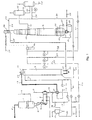
- the apparatus which is schematically shown in figure 1 comprises a vertical steaming vessel 1, a horizontal steaming vessel 2, a vertical impregnation vessel 3 and a vertical digester 4, which operates according to the steam-liquid phase principle.
- the horizontal steaming vessel may be excluded if wished.
- the chips are fed through a line 5 to the vertical steaming vessel 1, to which low pressure steam or alternatively flash steam is added through a line 6 for heating of the chips and decreasing their content of air. Separated air can be removed through a line 7, which is connected to the horizontal steaming vessel 2. This pre-steaming is conducted at atmospheric pressure.
- the heated chips are measured with a chip meter, which is arranged in a connection 8 between the two steaming vessels 1, 2, which connection 8 also comprises a low pressure feeder 9, which sluices the chips into the horizontal steaming vessel 2, in which the pressure is 1-1.5 bar overpressure.
- the chips fall from the pressurised steaming vessel 2 into a chute 10, which has a high pressure feeder 11 arranged in its lower part. A certain level of liquid is maintained in the chute 10.
- a top circulation which comprises a feed line 12 for a mixture of chips and impregnation liquid, and a return line 13 for separated impregnation liquid.
- a downwards feeding top separator 14 is arranged in the top of the impregnation vessel 3 for feeding of the chips into the impregnation vessel at the same time as a part of the impregnation liquid is separated off and is pumped with a pump 15 through the return line 13, back to the high pressure feeder 11.
- the high pressure feeder 11 is equipped with a rotor with pockets, whereby one pocket always is in low pressure position, to be in open connection with the steaming vessel 2 and one pocket always, at the same time, is in high pressure position, to be in open connection with the impregnation vessel 3 via the feed line 12, which is connected to the top of the impregnation vessel.
- a rotor pocket which is filled with chips, arrives in high pressure position, that is in direct connection with the top circulation, it is flushed clean by the liquid from the return line 13, and the suspension of chips and impregnation liquid is fed into the top of the impregnation vessel 3 via the feed line 12.
- Liquid, in a circulation loop 17, which is equipped with a pump 16, is at the same time feeding chips from the chute 10 into one of the pockets of the high pressure feeder so that this pocket is filled with chips.
- the circulation loop 17 is, via a line 18, connected with a level tank 19, which in its turn, via a line 20, is connected to the return line 13 of the top circulation.
- Suitable impregnation liquid which may comprise black liquor and white liquor and optionally other chemicals, is added to the top circulation.
- Black liquor is added through a line 21 and white liquor through a line 22, which two lines are connected to the return line 13, via the line 20.
- the impregnation vessel 3, itself, is, in accordance with the present invention, in the shown embodiment, completely free from an arrangement for withdrawal of liquid from the impregnation phase of the cooking system, at a location between the inlet 23 and the outlet 24 of the impregnation vessel. Consequently, the impregnation vessel 3 presents a longish cylindrical tube, which is completely free from a cost increasing withdrawal screen for withdrawal of liquid from the impregnation phase and removal of this liquid from the cooking system.
- a transfer circulation which comprises a feed line 25 for the mixture of impregnated chips and liquid and a return line 26 for separated liquid.
- the feed line 25 is, by one of its ends, connected to an outlet end 27 of the impregnation vessel 3, which outlet end 27 thus comprises said outlet 24, and by its other end, to a top separator 28, which is arranged in the top of the digester 4 for separation of liquid from the chip-liquid mixture that has been fed in.
- the top separator 28 has a vertically arranged screw 29, which is driven by a motor 30, and a cylindrical body, in which the screw 29 rotates and which has a lower screen part 31 and a thereby following, upper part 32 which is not broken through and presents a free upper edge 33.
- the screen part 31 is surrounded by a concentric wall 34, which is not broken through, for formation of a liquid chamber 35, there between for collection of liquid, which is pressed out through the screen part 31 under influence of the screw 29.
- the screenface 31 is preferably designed in accordance with our design described in PCT/SE94/00315, i.e.
- a ring shaped supply conduit 36 is arranged around the screw 29 within the area of the part 32, which is not broken through. Holes 37 are arranged in the supply conduit 36 and the part 32 which is otherwise not broken through for addition of white liquor and possibly other liquid to the chips, which moves upwards in the screw room 38 and from which a large part of the free liquid has been pressed out through the screen part 31, just before.
- the supply space 36 and the withdrawal space 35 are separated in a sealed manner. In the preferred case the distance between the supply space 36 and the upper edge of the screen 31 is less than the diameter (Ds) of the screw 29.
- the outer wall 34 of the withdrawal space 35 may be integral with the outer wall of the supply space 36.
- the feed line 25 is connected to the bottom of the top separator 28.
- the return line 26 is connected to the liquid chamber 35.
- Medium pressure steam may be added via a line 39, to the upper steam room of the digester in the top of the digester 4 in connection with the top separator 28 in order to heat the chips (and free liquid) that are fed in by the screw 29 and which fall down over the free edge 33 of the part 32, which is not broken through.
- the digester 4 has, within its middle part, a withdrawal screen 40 for withdrawal of black liquor via a line 41, that is connected to a first flash cyclone 42, which is in connection with a second flash cyclone 43 via a line 44. Effluent from the second flash cyclone 43 is led via a line 45, completely or partly, to a recovery plant (not shown).
- the steam which is formed in the flash cyclones 42, 43 can be used in different locations in the cooking process, for example for the steaming in the steaming vessels 1, 2.
- a bottom circulation which comprises a withdrawal screen 46 and a circulation line 49, which is equipped with a pump 47 and a heat exchanger 48, and which comprises a central line 50 that mouths at the withdrawal screen 46.
- Wash liquid is added to the bottom part of the digester 4 via a line 51.
- the digested chips are fed out through an outlet in the bottom of the digester 4 and are led away through a line 52 for further treatment.
- the top separator 28 is further, with its liquid chamber 35, connected with the other flash cyclone 43 via a connection 53 which, in the embodiment shown, comprises the return line 26 and a branch line 54 to the same.
- a prechosen amount of liquid from the cooking system is withdrawn through the connection 53, which thus takes place with an existing screen device, that is, the top separator 28 in the digester which thereby achieves yet another function when it takes over the function of the conventional withdrawal screen in the impregnation vessel.
- the withdrawn liquid is led directly to recovery, without passing the flash cyclone.
- White liquor is added to the top of the digester 4, via a line 55 which passes a heat exchanger 56.
- This heat exchanger can alternatively be excluded.
- a line 57 connects the return line 26 with the line 55 for white liquor for addition of withdrawn liquid from the top separator 28, when wished.
- This line 57 can alternatively be excluded.
- a line 58 is, further, connected to the line 55 for white liquor, for addition of wash liquid when wished.
- the heat exchanger 56 may work with low pressure steam, medium pressure steam or flash steam.
- An advantage of the invention is that the transfer circulation does not need to be heated, which means that chips which are fed out from the impregnation vessel 3 can keep a lower temperature than before, for example 130°C as compared to previous 145°C, which in its turn has a beneficial effect on the pulp quality.
- the lower temperature in the transfer circulation will additionally decrease the risk of the problems which may occur in the top separator at the previously used high temperatures.
- the inlet for the white liquor is preferably situated inside the top separator in a blind zone 32, which surrounds the screw 29 and which is located above the screen part 31 itself.
- a good mixing of chips and white liquor is thereby secured by means of the influence of the screw 29, before the chips and the white liquor are fed out from the screw and fall down into the steam room of the digester. It is beneficial that the chips contain at least a small amount of free liquid when they leave the screen part 31 and are fed up into the blind zone 32, in order to thereby prevent that white liquor is drawn down into the screen part and is pressed out into the liquid chamber.
- the relation between liquid and wood at the inlet of the impregnation vessel can, for example, be 3.5/1, but the invention makes it possible to use larger amounts of liquid, as for example up to 6/1 and above.
- the pressure in the impregnation vessel can, for example, be 10 bar overpressure and the temperature can, for example, be kept at 115-120°C at the top or lower for example 90-100°C. Any displacement of liquid by withdrawal of liquid from the cooking system does thus not take place in the impregnation vessel.
- White liquor is added to the top of the digester in an amount which is enough to obtain the wished delignification of the chips.
- the impregnated chips avail the white liquor through diffusion.
- Steam is added to adjust the cooking temperature to the wished level, for example within 140-170°C.
- the liquid which is pressed out from the screw 29 and is collected in the liquid chamber 35 can be distributed in a suitable way with respect to transfer liquid, which is fed to the impregnation vessel via the return line 26, liquid which is complementary to the white liquor which is withdrawn through the line 57, and liquid which is withdrawn from the cooking system via the connection 53, that is, the line 26 and the branch line 54.
- the relation can, in the order given, be 20-30 m3/ADMT of pulp (to the impregnation vessel), 0-4 m3/ADMT of pulp (via the line 57) and 0.5-10 m3/ADMT of pulp (via the branch line 54), or sometimes even as much as 12-15 m3/ADMT.
- FIG. 3 there is shown a further embodiment of a separator to be used in connection with a steam/vapour phase digester, as described in figure 2.
- the separator of Fig. 3 is almost identical with the one shown in Fig. 2 except for the existence of a further supply space 25, being positioned below the first supply space 23.
- This further supply space 25 has as its object to provide for the possibility of supplying a further liquid to the up-moving chip pile. Especially for the possibility of supplying black liquor in order to secure a minimum amount of free liquid flowing upwardly in the chips pile, to eliminate back flow of the cooking liquor supplied above, in 23.
- a liquid collecting space 67 which may be connected to the return pipe circulation 15.
- a liquid supply space or opening 23 which is connected to the supply line 24 that supplies white liquor (F).
- the separator also has a plurality of inlet apertures 37 defined therein to subject the fiber chips with white liquor.
- the inlet apertures preferably has a total area that exceeds 400 mm2. More preferred, the total area of the inlet apertures is at least 500 mm2. Most preferred, the total area of the inlet apertures exceeds 600 mm2 to achieve a sufficient flow into the chip pile.
- top separator Between the outer peripheral wall 66 of the liquid collecting space 67 and the liquid supply space 23 respectively, and the digester shell 6 at the top, there exist an annular space 70 which opens up down into the upper part of the digester 6.
- the functioning of the top separator may be described as follows.
- the thoroughly heated and impregnated chips are transferred by means of the supply line 21 into the bottom portion of the screen basket 61.
- the screw feeder 62 moves the chips upwardly at the same time as the transport liquid D is separated from the chips, by being withdrawn outwardly through the screen basket 61 and further out of the digester through return line 15. More and more liquid will be withdrawn from the chips during their transport within the screen basket 61.
- the chips will reach the level of the first supply space 25 where a desired liquor, for instance black liquor, is supplied.
- the chips will reach the level of the supply space 23.
- the desired amount of cooking liquor preferably white liquor, is added through the supply space 23 and the openings 37, having a temperature and effective alkaline content in accordance with the invention.
- a minor amount of free liquid (at least about 0.5 m3/ADT) should be left together with the chips, which free liquid will then be mixed with the supplied cooking liquor. As explained above this may also be achieved by means of supply of free liquid through the intermediate supply space 25. Preferably, about one m3/ADT should be left together with the fiber material. Additionally, the white liquor should be provided at a point that is downstream of the flow of the suspension of the fiber material and the free liquid that is being fed through the screw member.
- the chips and the cooking liquor may flow over the upper edge thereof and fall into the steam liquid space 70 and further on to the top of the chips pile within the digester, where the concurrent cooking zone (B) starts.
- a major advantage of the separation device is that they provide for establishing a distinguished change of zones (they enable almost a total exchange of free liquid at this point), which means that for a two vessel system the desired conditions in the beginning of the concurrent zone (B) can easily be established.
- Fig. 4 there is shown a diagram comparing the H-factor for pulp produced according to a conventional ITC TM -cooking process and according to the cooking process of the present invention.
- the H-factor is a function of time and temperature in relation to the delignification process (degree of delignification) during the cooking process.
- the H-factor is used to control the delignification process of a digester, i.e., maintaining a certain H-factor principally leads to the same Kappa number of the produced pulp (remaining lignin content of the fiber material) independent of any temperature variations during the cooking process.
- Fig. 5 it is shown that the H-factor for pulp produced according to the present invention is extremely much lower (about 40-50% lower) compared to pulp produced according to ITC. This means that much lower temperatures may be used for the same retention time in order to reach a certain degree of delignification (Kappa number) and/or that smaller vessels for the cooking within a continuous digester can be used and/or that a lower Kappa number may be achieved with the same kind of basic equipment and/or that higher rate of production can be obtained.
- Kappa number degree of delignification
- the lower H-factor demand is achieved by a high alkali concentration and a low cooking temperature in the concurrent cooking zone, which presents one reference ITC-cook (ITC 1770) and one cook according to the present invention (modified ITC* 1763).
- ITC 1770 one reference ITC-cook
- modified ITC* 1763 modified ITC* 1763.
- the temperature in the counter-current cooking zone, according to the present invention is higher than in the concurrent zone but still lower than the temperature in the counter-current zone in the ITC-reference.
- Fig. 6 shows results from TCF bleaching using the novel cooking process (so called "new concept") of the present invention compared to a conventional reference cooking process.
- the present invention provides a TCF-bleached pulp having extremely good bleachability, i.e. a higher brightness is achieved compared to the conventional process for the same amount of peroxide consumption, and also a higher brightness ceiling is obtained.
- Fig. 7 shows the tear index relative to the tensile index.
- the test data compares results obtained by the novel cooking process ("new concept") of the present invention with a conventional cooking process ("ITC-reference").
- Fig. 8 compares test data for the novel process with those from a conventional process. As can be seen the present invention exhibits better tensile index compared to the conventional method.
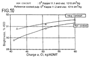
- Fig. 9 shows the brightness level by using the novel process ("new concept") with reference cooked pulp.
- the novel cooking process of the present invention exhibits a higher brightness compared to the conventional cooking process.
- the black liquor supplied into the impregnation zone A has a high content of rest alkali, (effective alkali EA as NaOH), at least 13g/l, preferably about or above 16g/l and more preferred between 13-30g/l in the top of the impregnation zone A.
- This alkali mainly comes from the black liquor due to the high amount of alkali in the concurrent zone B of the digester 6h.
- the strength properties of the fibers are positively affected by the impregnation because of the high amount of sulphide.
- a major portion of the black liquor may directly (or via one flash tank) be fed into the impregnation zone A.
- the total supply of black liquor to the impregnation zone A may exceed 80% of the amount drawn off from the draw-off screen girdle section 104h, preferably more than 90% and optimally about 100% of the total flow, which normally is about 8-12 m 3 /ADT.
- the retention time in the impregnation zone A should be at least 20 minutes, preferably at least 30 minutes and more preferred at least 40 minutes. However, a shorter retention time than 20 minutes, such as 15-20 minutes may also be used.
- the invention may also be performed in connection with an impregnation vessel having the inlet at the bottom and which accordingly has an upward flow of the chips.
- an impregnation vessel having the inlet at the bottom and which accordingly has an upward flow of the chips.
- a number of nozzles may be used, or even spray nozzles as described in PCT/SE94/01230.
Landscapes
- Paper (AREA)
Abstract
Description
- The present invention relates to a novel top separator for wood chips positioned within the top of a digester, a method for producing pulp, preferably sulphate cellulose, with the aid of continuous digester systems using the top separator and an apparatus comprising said top separator.
- Environmental demands has forced our industry to develop improved cooking and bleaching methods. One recent breakthrough within the field of cooking is ITC™, which was developed in 1992-1993. ITC™ is described in WO-9411566, which shows that very good results concerning the pulp quality may be achieved. ITC™ is mainly based on using almost the same temperature (relatively low compared to prior art) in all cooking zones in combination with moderate alkaline levels. The ITC™-concept does not merely relate to the equalization of temperatures between different cooking zones, but a considerable contribution of the ITC™-concept relates to enabling an equalized alkaline profile also in the lower part of the counter-current cooking zone.
- Moreover, it is known that impregnation with the aid of black liquor can improve the strength properties of the fibers in the pulp produced. The aim of the impregnation is, in the first place, to thoroughly soak each chip so that it becomes susceptible, by penetration and diffusion, to the active cooking chemicals which, in the context of sulphate cellulose, principally consist of sodium hydroxide and sodium sulphide.
- If, as is customary according to prior art, a large proportion of the white liquor is supplied in connection with the impregnation, there will exist no distinct border between impregnation and cooking. This leads to difficulties in optimizing the conditions in the transition zone between impregnation and cooking.
In US 5.089.086 is shown a method where ccooking liqour is added to the fibre material in the digester after the wood chips are transferred to the upper part of the digester and below the top separator.
Now it has been found that surprisingly good results can be achieved when: - 1. Keeping a low temperature but a high alkali content in the beginning of a concurrent cooking zone of the digester;
- 2. Withdrawing a substantial part of a highly alkaline spent liquor that has passed through at least the concurrent cooking zone; and
- 3. Supplying a substantial portion of the withdrawn spent liquor that has a relatively high amount of rest-alkali, to a point that is adjacent the beginning of an impregnation zone.
- This leads to a reduced H-factor demand, reduced consumption of cooking chemicals and better heat-economy. Additionally, the novel method leads to production of pulp that has a high quality and a very good bleachability, which means that bleach chemicals and methods can be chosen with a wider variety than before for reaching desired quality targets (brightness, yield, tear-strength, viscosity, etc.) of the finally bleached pulp. This novel process is defined in more detail in our co-pending application PCT/SE97/00192.
- The present invention relates to a preferred top separator, a method and an apparatus for practising the above. In connection with the continuous cooking of cellulose containing fibre material, it comprises impregnation of the fibre material with an impregnation liquid in an impregnation vessel and cooking of the impregnated fiber material in a digester, the impregnation vessel and the digester being connected to each other by a transfer circulation, which, via a feed line, feeds the fibre material from an outlet end of the impregnation vessel to the top of the digester, which feed-line comprises a separator for separation of free liquid from the fibre material and, which via a return line, feeds separated liquid back to the outlet end of the impregnation vessel for use as transfer liquid for the impregnated fibre material. According the inventive top separator, method and apparatus is cooking liquid added to the fibre material in the top separator and after separation of the free liquid, in the top separator, downstream said separation of liquid in said top separator under the influence of an upwards feeding screw in the top separator.
- According to conventional technique for withdrawal of liquid from the cooking system, this is normally done directly from the withdrawal strainer of the digester itself. Alternatively in connection with a two vessel system the impregnation vessel, may be supplied with fresh cooking liquor and equipped with a screening device, from which some of the withdrawn liquid is transferred to a recovery plant, possibly after first having passed a flash cyclone. The use of such a screening device involves a considerable cost, due to a special construction of the impregnation vessel being necessary, assembly of conduits and installation of screens, blind plates, nozzles, a possible central line and different instruments in addition to labour for assembling, welding etc. In addition to this there are difficulties in optimizing the withdrawal at this point. Moreover the operating costs of such a screening device is not neglectable. Furthermore the addition of white liquor (fresh cooking liquid) within the impregnation vessel or in the transfer circulation line leads to difficulties in optimizing the process. Firstly when supplying to the impregnation vessel it can be difficult to achieve sufficient mixing of the added white liquor in the impregnation vessel, leading to varying levels of alkaline in different parts. Secondly different kind of wood chips may consume varying amounts of alkaline, making it more difficult to optimize the conditions in the impregnation vessel. It is even claimed that the above might have a bad influence on cost and the quality of pulp, since if a too high amount of alkaline exists in connection with the mechanical action of the outlet scraper might deteriorate fibre strength.
- The object of the present invention is to improve and simplify the cooking department with respect to withdrawal and supply of liquid from the cooking system. This is achieved by the use of a new method in connection with a new separator, also leading to a simplified construction of the impregnation vessel with resulting savings in material and costs and to a better way of optimizing withdrawal and supply of liquid thereby also creating conditions for a better utilisation of the cooking liquid.
- The top separator for wood wood chips according to the invention is characterised by the characterising features of claim 1.
- According to a further aspect of the invention, i.e. according the inventive method making use of said top separator, a first part, less than 100%, preferably less than 95% and more preferred less than 90% of the liquid which is separated from the fibre material in the top separator is recirculated to be used as transfer liquid for the impregnated fibre material and/or to be re-used in connection with the impregnation vessel, either as a transfer liquid or as an impregnation liquid,
and that cooking liquid is added after separation of transfer liquid to the chips in the separator via a number of symmetrically positioned inlet apertures in a ring-shaped conduit positioned around the top of the feed screw in order for said cooking liquid to be intimately mixed with the fibre material which is poor in liquid, by influence of the upwards feeding screw in the top separator, before the chips and the cooking liquor are fed out from the screw. - Further the apparatus according to the invention is characterised in that it comprises a connection, which via a branch stretches from the liquid chamber of the separator to a recovery plant for withdrawal via branch of a second part of the liquid which is separated by the separator from the cooking system, and that the top separator has a cylindrical upper part which is located above a cylindrical screen part, which is surrounded by said liquid chamber, whereby the upward feeding screw co-operates with the upper part and the screen part, and that said line for cooking liquor is connected to the separator via an annual ring shaped conduit, which surrounds said upper part and which, via a number of symmetrically positioned inlet apertures in the upper part communicates with the screw room for even addition and intimate mixing-in of cooking liquor into the fibre material by means of influence of the screw before the chips and the cooking liquid are fed out from the screw.
- According to a preferred embodiment of the invention, the mixture of fibre material and impregnation liquid is fed through the entire impregnation vessel, without liquid being withdrawn from the cooking via the impregnation vessel, besides which a second part of the liquid which is separated in the separator is transferred to recovery.
- It is preferred that the second part of the withdrawn liquid is allowed to flash before the recovery.
- The second part of the withdrawn liquid may suitably constitute at most 20 m3/ADMT of pulp and at least 0.5 m3/ADMT of pulp, preferably at least 2 m3/ADMT of pulp and more preferred at least 4 m3/ADMT of pulp. It is suitable that liquid is separated from the fibre material in a controlled amount, so that the fibre material contains at least 0.5 m3 free liquid/ADMT of pulp.
- According to the invention, cooking liquid is added to the separator after separation of liquid in order to be intimately mixed with the fibre material which is poor in liquid, by influence of an upwards feeding screw in the top separator.
- The said second part of liquid is suitably withdrawn from said return line via a branch line, directly or indirectly, outside the fibre material to the recovery without any essential part thereof being recirculated to the digester.
- The invention will in the following be further explained by an example, with reference to the drawings.
- Fig. 1 shows schematically a preferred two vessel digester according to the invention.
- Fig. 2 shows a preferred embodiment of a separator positioned in the upper part of the digester according to figure 1.
- Fig. 3 is a cross-sectional view of a further embodiment of a separator according to the present invention;
- Fig. 4 shows a diagram presenting the advantages related to the H-factor when using the invention;
- Fig. 5 shows which conditions were used in the laboratory for one of the ITC-references and one of the cooking methods according to the invention (so called modified ITC);
- Fig. 6 shows test data related to peroxide consumption and brightness for the present (compact) method compared to a conventional process;
- Fig. 7 shows test data related to tensile index and tear index for the present (compact) method compared to a conventional process;
- Fig. 8 shows test data related to tensile index and tear index for the present compact method compared to a conventional process;
- Fig. 9 shows test data related to Cl charge and brightness for the present (compact) method compared to a conventional process
- The invention is described in connection with the production of sulphate pulp with wood chips as raw material, but it is of course applicable for production of other types of pulp and with any type of suitable raw materials consisting of cellulose containing fibre material, e.g. bagasse, saw dust, etc.
- The apparatus which is schematically shown in figure 1 comprises a vertical steaming vessel 1, a
horizontal steaming vessel 2, avertical impregnation vessel 3 and avertical digester 4, which operates according to the steam-liquid phase principle. The horizontal steaming vessel may be excluded if wished. The chips are fed through aline 5 to the vertical steaming vessel 1, to which low pressure steam or alternatively flash steam is added through aline 6 for heating of the chips and decreasing their content of air. Separated air can be removed through a line 7, which is connected to thehorizontal steaming vessel 2. This pre-steaming is conducted at atmospheric pressure. The heated chips are measured with a chip meter, which is arranged in aconnection 8 between the two steamingvessels 1, 2, whichconnection 8 also comprises a low pressure feeder 9, which sluices the chips into thehorizontal steaming vessel 2, in which the pressure is 1-1.5 bar overpressure. The chips fall from thepressurised steaming vessel 2 into achute 10, which has a high pressure feeder 11 arranged in its lower part. A certain level of liquid is maintained in thechute 10. - Between the high pressure feeder 11 and the
impregnation vessel 3, there is a top circulation, which comprises afeed line 12 for a mixture of chips and impregnation liquid, and areturn line 13 for separated impregnation liquid. A downwards feedingtop separator 14 is arranged in the top of theimpregnation vessel 3 for feeding of the chips into the impregnation vessel at the same time as a part of the impregnation liquid is separated off and is pumped with apump 15 through thereturn line 13, back to the high pressure feeder 11. The high pressure feeder 11 is equipped with a rotor with pockets, whereby one pocket always is in low pressure position, to be in open connection with the steamingvessel 2 and one pocket always, at the same time, is in high pressure position, to be in open connection with theimpregnation vessel 3 via thefeed line 12, which is connected to the top of the impregnation vessel. When a rotor pocket, which is filled with chips, arrives in high pressure position, that is in direct connection with the top circulation, it is flushed clean by the liquid from thereturn line 13, and the suspension of chips and impregnation liquid is fed into the top of theimpregnation vessel 3 via thefeed line 12. Liquid, in acirculation loop 17, which is equipped with apump 16, is at the same time feeding chips from thechute 10 into one of the pockets of the high pressure feeder so that this pocket is filled with chips. Thecirculation loop 17 is, via aline 18, connected with alevel tank 19, which in its turn, via aline 20, is connected to thereturn line 13 of the top circulation. - Suitable impregnation liquid, which may comprise black liquor and white liquor and optionally other chemicals, is added to the top circulation. Black liquor is added through a
line 21 and white liquor through aline 22, which two lines are connected to thereturn line 13, via theline 20. - The
impregnation vessel 3, itself, is, in accordance with the present invention, in the shown embodiment, completely free from an arrangement for withdrawal of liquid from the impregnation phase of the cooking system, at a location between theinlet 23 and theoutlet 24 of the impregnation vessel. Consequently, theimpregnation vessel 3 presents a longish cylindrical tube, which is completely free from a cost increasing withdrawal screen for withdrawal of liquid from the impregnation phase and removal of this liquid from the cooking system. - Between the
impregnation vessel 3 and thedigester 4, there is a transfer circulation, which comprises afeed line 25 for the mixture of impregnated chips and liquid and areturn line 26 for separated liquid. Thefeed line 25 is, by one of its ends, connected to anoutlet end 27 of theimpregnation vessel 3, which outlet end 27 thus comprises saidoutlet 24, and by its other end, to atop separator 28, which is arranged in the top of thedigester 4 for separation of liquid from the chip-liquid mixture that has been fed in. - As is more readily apparent from figure 2, the
top separator 28 has a vertically arrangedscrew 29, which is driven by amotor 30, and a cylindrical body, in which thescrew 29 rotates and which has alower screen part 31 and a thereby following,upper part 32 which is not broken through and presents a freeupper edge 33. Thescreen part 31 is surrounded by aconcentric wall 34, which is not broken through, for formation of aliquid chamber 35, there between for collection of liquid, which is pressed out through thescreen part 31 under influence of thescrew 29.
Thescreenface 31 is preferably designed in accordance with our design described in PCT/SE94/00315, i.e. by the use of rigid vertically arranged rods, which are welded onto support rings so as to form gaps of about 3-10 mm, preferably about 4-7 mm, there between.
A ring shapedsupply conduit 36 is arranged around thescrew 29 within the area of thepart 32, which is not broken through.Holes 37 are arranged in thesupply conduit 36 and thepart 32 which is otherwise not broken through for addition of white liquor and possibly other liquid to the chips, which moves upwards in thescrew room 38 and from which a large part of the free liquid has been pressed out through thescreen part 31, just before. Thesupply space 36 and thewithdrawal space 35 are separated in a sealed manner. In the preferred case the distance between thesupply space 36 and the upper edge of thescreen 31 is less than the diameter (Ds) of thescrew 29. According to the alternative shown in fig. 2 they are positioned directly on top of each other, which is achieved by means of aconcentric ring plate 69, e.g. by the use of welding. Also according to the shown embodiment theouter wall 34 of thewithdrawal space 35 may be integral with the outer wall of thesupply space 36.
Thefeed line 25 is connected to the bottom of thetop separator 28. Thereturn line 26 is connected to theliquid chamber 35. Medium pressure steam may be added via aline 39, to the upper steam room of the digester in the top of thedigester 4 in connection with thetop separator 28 in order to heat the chips (and free liquid) that are fed in by thescrew 29 and which fall down over thefree edge 33 of thepart 32, which is not broken through. - The
digester 4 has, within its middle part, awithdrawal screen 40 for withdrawal of black liquor via aline 41, that is connected to a first flash cyclone 42, which is in connection with asecond flash cyclone 43 via aline 44. Effluent from thesecond flash cyclone 43 is led via aline 45, completely or partly, to a recovery plant (not shown). The steam which is formed in theflash cyclones 42, 43 can be used in different locations in the cooking process, for example for the steaming in thesteaming vessels 1, 2. In the digester there is, in addition to top and middle circulations, a bottom circulation, which comprises awithdrawal screen 46 and a circulation line 49, which is equipped with apump 47 and aheat exchanger 48, and which comprises acentral line 50 that mouths at thewithdrawal screen 46. Wash liquid is added to the bottom part of thedigester 4 via aline 51. The digested chips are fed out through an outlet in the bottom of thedigester 4 and are led away through aline 52 for further treatment. - The
top separator 28 is further, with itsliquid chamber 35, connected with theother flash cyclone 43 via aconnection 53 which, in the embodiment shown, comprises thereturn line 26 and abranch line 54 to the same. A prechosen amount of liquid from the cooking system is withdrawn through theconnection 53, which thus takes place with an existing screen device, that is, thetop separator 28 in the digester which thereby achieves yet another function when it takes over the function of the conventional withdrawal screen in the impregnation vessel. In an alternative embodiment, the withdrawn liquid is led directly to recovery, without passing the flash cyclone. - White liquor is added to the top of the
digester 4, via aline 55 which passes aheat exchanger 56. This heat exchanger can alternatively be excluded. Aline 57 connects thereturn line 26 with theline 55 for white liquor for addition of withdrawn liquid from thetop separator 28, when wished. Thisline 57 can alternatively be excluded. Aline 58 is, further, connected to theline 55 for white liquor, for addition of wash liquid when wished. Theheat exchanger 56 may work with low pressure steam, medium pressure steam or flash steam. - Instead of withdrawing liquid from a screen section in the impregnation vessel, necessary withdrawal of liquid is thus conducted on the liquor side of the transfer circulation.
- An advantage of the invention is that the transfer circulation does not need to be heated, which means that chips which are fed out from the
impregnation vessel 3 can keep a lower temperature than before, for example 130°C as compared to previous 145°C, which in its turn has a beneficial effect on the pulp quality. The lower temperature in the transfer circulation will additionally decrease the risk of the problems which may occur in the top separator at the previously used high temperatures. - By adding the white liquor to the fibre material in connection with the
top separator 28 downstream the location for the separation of the liquid, that is downstream thescreen part 31, this addition of white liquor becomes completely separated from the transfer circulation so that the entire amount of white liquor normally can be used in thedigester 4. The inlet for the white liquor is preferably situated inside the top separator in ablind zone 32, which surrounds thescrew 29 and which is located above thescreen part 31 itself. A good mixing of chips and white liquor is thereby secured by means of the influence of thescrew 29, before the chips and the white liquor are fed out from the screw and fall down into the steam room of the digester. It is beneficial that the chips contain at least a small amount of free liquid when they leave thescreen part 31 and are fed up into theblind zone 32, in order to thereby prevent that white liquor is drawn down into the screen part and is pressed out into the liquid chamber. - The relation between liquid and wood at the inlet of the impregnation vessel can, for example, be 3.5/1, but the invention makes it possible to use larger amounts of liquid, as for example up to 6/1 and above. The pressure in the impregnation vessel can, for example, be 10 bar overpressure and the temperature can, for example, be kept at 115-120°C at the top or lower for example 90-100°C. Any displacement of liquid by withdrawal of liquid from the cooking system does thus not take place in the impregnation vessel.
- White liquor is added to the top of the digester in an amount which is enough to obtain the wished delignification of the chips. The impregnated chips avail the white liquor through diffusion. Steam is added to adjust the cooking temperature to the wished level, for example within 140-170°C.
- The liquid which is pressed out from the
screw 29 and is collected in theliquid chamber 35 can be distributed in a suitable way with respect to transfer liquid, which is fed to the impregnation vessel via thereturn line 26, liquid which is complementary to the white liquor which is withdrawn through theline 57, and liquid which is withdrawn from the cooking system via theconnection 53, that is, theline 26 and thebranch line 54. The relation can, in the order given, be 20-30 m3/ADMT of pulp (to the impregnation vessel), 0-4 m3/ADMT of pulp (via the line 57) and 0.5-10 m3/ADMT of pulp (via the branch line 54), or sometimes even as much as 12-15 m3/ADMT. By attaching a line between thewithdrawal screen 40 and the top of theimpregnation vessel 3 the system shown in Fig. 1 may easily be connected to run according to the novel process, which process is described in more detail in our co-pending application PCT/SE97/00192 and also in connection with figures 4 and 11 herein. - In Figure 3 there is shown a further embodiment of a separator to be used in connection with a steam/vapour phase digester, as described in figure 2. The separator of Fig. 3 is almost identical with the one shown in Fig. 2 except for the existence of a
further supply space 25, being positioned below thefirst supply space 23. Thisfurther supply space 25 has as its object to provide for the possibility of supplying a further liquid to the up-moving chip pile. Especially for the possibility of supplying black liquor in order to secure a minimum amount of free liquid flowing upwardly in the chips pile, to eliminate back flow of the cooking liquor supplied above, in 23. - As in fig. 2 circumjacent the
screen basket 61 there is arranged aliquid collecting space 67, which may be connected to thereturn pipe circulation 15. Above theliquid collecting space 67, also circumjacent thescreen basket 61, there is arranged a liquid supply space oropening 23 which is connected to thesupply line 24 that supplies white liquor (F). The separator also has a plurality ofinlet apertures 37 defined therein to subject the fiber chips with white liquor. The inlet apertures preferably has a total area that exceeds 400 mm2. More preferred, the total area of the inlet apertures is at least 500 mm2. Most preferred, the total area of the inlet apertures exceeds 600 mm2 to achieve a sufficient flow into the chip pile. Between the outerperipheral wall 66 of theliquid collecting space 67 and theliquid supply space 23 respectively, and thedigester shell 6 at the top, there exist anannular space 70 which opens up down into the upper part of thedigester 6. The functioning of the top separator may be described as follows. - The thoroughly heated and impregnated chips are transferred by means of the
supply line 21 into the bottom portion of thescreen basket 61. Here thescrew feeder 62 moves the chips upwardly at the same time as the transport liquid D is separated from the chips, by being withdrawn outwardly through thescreen basket 61 and further out of the digester throughreturn line 15. More and more liquid will be withdrawn from the chips during their transport within thescreen basket 61. First the chips will reach the level of thefirst supply space 25 where a desired liquor, for instance black liquor, is supplied. Eventually, the chips will reach the level of thesupply space 23. Here the desired amount of cooking liquor, preferably white liquor, is added through thesupply space 23 and theopenings 37, having a temperature and effective alkaline content in accordance with the invention. - In order to eliminate the risk of back flowing of the supplied liquid from the
supply space 23 into theliquid collection space 67, a minor amount of free liquid (at least about 0.5 m3/ADT) should be left together with the chips, which free liquid will then be mixed with the supplied cooking liquor. As explained above this may also be achieved by means of supply of free liquid through theintermediate supply space 25. Preferably, about one m3/ADT should be left together with the fiber material. Additionally, the white liquor should be provided at a point that is downstream of the flow of the suspension of the fiber material and the free liquid that is being fed through the screw member. - At the top of the
screen basket 61, the chips and the cooking liquor may flow over the upper edge thereof and fall into thesteam liquid space 70 and further on to the top of the chips pile within the digester, where the concurrent cooking zone (B) starts. - A major advantage of the separation device is that they provide for establishing a distinguished change of zones (they enable almost a total exchange of free liquid at this point), which means that for a two vessel system the desired conditions in the beginning of the concurrent zone (B) can easily be established.
In Fig. 4, there is shown a diagram comparing the H-factor for pulp produced according to a conventional ITC™-cooking process and according to the cooking process of the present invention. The H-factor is a function of time and temperature in relation to the delignification process (degree of delignification) during the cooking process. The H-factor is used to control the delignification process of a digester, i.e., maintaining a certain H-factor principally leads to the same Kappa number of the produced pulp (remaining lignin content of the fiber material) independent of any temperature variations during the cooking process. - In Fig. 5, it is shown that the H-factor for pulp produced according to the present invention is extremely much lower (about 40-50% lower) compared to pulp produced according to ITC. This means that much lower temperatures may be used for the same retention time in order to reach a certain degree of delignification (Kappa number) and/or that smaller vessels for the cooking within a continuous digester can be used and/or that a lower Kappa number may be achieved with the same kind of basic equipment and/or that higher rate of production can be obtained.
- The lower H-factor demand is achieved by a high alkali concentration and a low cooking temperature in the concurrent cooking zone, which presents one reference ITC-cook (ITC 1770) and one cook according to the present invention (modified ITC* 1763). As shown, the temperature in the counter-current cooking zone, according to the present invention, is higher than in the concurrent zone but still lower than the temperature in the counter-current zone in the ITC-reference.
- Fig. 6 shows results from TCF bleaching using the novel cooking process (so called "new concept") of the present invention compared to a conventional reference cooking process. The present invention provides a TCF-bleached pulp having extremely good bleachability, i.e. a higher brightness is achieved compared to the conventional process for the same amount of peroxide consumption, and also a higher brightness ceiling is obtained.
- Fig. 7 shows the tear index relative to the tensile index. The test data compares results obtained by the novel cooking process ("new concept") of the present invention with a conventional cooking process ("ITC-reference").
- Similarly, Fig. 8 compares test data for the novel process with those from a conventional process. As can be seen the present invention exhibits better tensile index compared to the conventional method.
- Fig. 9 shows the brightness level by using the novel process ("new concept") with reference cooked pulp. The novel cooking process of the present invention exhibits a higher brightness compared to the conventional cooking process.
- According to the novel process the black liquor supplied into the impregnation zone A has a high content of rest alkali, (effective alkali EA as NaOH), at least 13g/l, preferably about or above 16g/l and more preferred between 13-30g/l in the top of the impregnation zone A. This alkali mainly comes from the black liquor due to the high amount of alkali in the concurrent zone B of the
digester 6h. Furthermore, the strength properties of the fibers are positively affected by the impregnation because of the high amount of sulphide. A major portion of the black liquor may directly (or via one flash tank) be fed into the impregnation zone A. The total supply of black liquor to the impregnation zone A may exceed 80% of the amount drawn off from the draw-offscreen girdle section 104h, preferably more than 90% and optimally about 100% of the total flow, which normally is about 8-12 m3/ADT. - The retention time in the impregnation zone A should be at least 20 minutes, preferably at least 30 minutes and more preferred at least 40 minutes. However, a shorter retention time than 20 minutes, such as 15-20 minutes may also be used. The volume of the impregnation zone A may be larger than 1/11, preferably larger than 1/10 of the volume of the
digester 6. Additionally, in the preferred embodiment, the volume V of the impregnation zone A should exceed 5 times the value of the square of the maximum digester diameter, i.e., V = 5D2, where D is the maximum diameter of thedigester 6.
The invention is not limited to what is described above, but can vary with the scope of the appendant claims. For example, the invention may also be performed in connection with an impregnation vessel having the inlet at the bottom and which accordingly has an upward flow of the chips. Furthermore it is understood that instead of an annular distribution ring for supply of cooking liquor, a number of nozzles may be used, or even spray nozzles as described in PCT/SE94/01230.
Claims (16)
- A separator (7) for wood chips disposed in the feed line between an impregnation vessel and a digester and positioned within the top of the digester comprising:a screw feeder (29) having an inlet end (25) and an outlet end (33) for feeding wood chips in an upward direction from the inlet end towards the outlet end of the screw feeder;a rotatable shaft (63)in operative engagement with the screw feeder;a drive unit (30) secured to the rotatable shaft for rotating the rotatable shaft;a cylindrical body with a lower screen basket (31) and an upper part (32) enclosing the screw feeder; anda liquid collecting space (35) enclosing the cylindrical screen basket (31) for separating a substantial portion of a free liquid, the liquid collecting space being in fluid communication with a return line (26) connected to the outlet end of the impregnation vessel; anda distribution means (36;23) for supplying a cooking liquid to the fiber material, said distribution means (36,23) being positioned downstream of the collecting space (35) in relation to the flow of the chips characterized in- that the distribution means is in the form of an annual ring-shaped conduit arranged around the screw (29) within the area of the upper part (32) of the cylindrical body,- that the total area of passage way between the annual ring (36,23) and the inner of the separator exceeds about 400mm2 in order to provide for sufficient flow capacity,- said passage way is formed by a number of symmetrically positioned, circular holes (37) in the upper part (32) of the cylindrical body which is otherwise not broken through.
- A separator according to claim 1
characterized in a recovery line (54) in fluid communication with said collecting space (35) to be withdraw a spent liquor from the return line fluid and conduct it to a recovery unit. - A separator according to claim 1 or 2
characterized in that said supply space (23) is positioned above the withdrawal space (35), whereby the distance between the upper edge of the screen (31;61) and said supply space (36;23) is less than the diameter (Ds)of the feed screw (29;62), preferably adjacently positioned by means of an outer wall (34) being integral for both the withdrawal space (35) and the supply space (36) and more, preferred directly above by means of a partition ring (69). - A separator according to any preceding claim
characterized in that there is a further supply space (25), preferably positioned intermediate said first supply space (23) and the withdrawal space (35), for supply of a different liquid than the liquid supplied through the first supply space. - Method in connection with continuous cooking of cellulose containing fibre material, comprising impregnation of the fibre material with impregnation liquid in an impregnation vessel (3) and cooking of the impregnated fibre material in a digester (4), the impregnation vessel (3) and the digester (4) being connected to each other by means of a transfer circulation, which partly, via a feed line (25), feeds the fibre material from an outlet end (27) of the impregnation vessel (3) to the top of the digester (4) for separation of free liquid from the fibre material in a separator (28) having an upwards feeding screw (29) in the top separator (28), and partly, via a return line (26), feeds separated liquid from the top of the digester (4) to the outlet end (27) of the impregnation vessel (3) for use as transfer liquid for the impregnated fibre material, and wherein liquid, comprising cooking liquid, is added to the fibre material in the top of the digester (4), downstream said separation of liquid in relation to the flow of the chips,
characterized in that, as a first part, less than 100%, preferably less than 95% and more preferred less than 90% of the liquid which is separated from the fibre material in the top separator is recirculated to be used as transfer liquid for the impregnated fibre material and/or to be re-used in connection with the impregnation vessel, either as a transfer liquid or as an impregnation liquid,
and that cooking liquid is added after separation of transfer liquid to the chips in the separator (28) via a number of symmetrically positioned inlet apertures in a ring-shaped conduit positioned around the top of the feed screw (29) in order for said cooking liquid to be intimately mixed with the fibre material which is poor in liquid, by influence of the upwards feeding screw (29) in the top separator (28), before the chips and the cooking liquor are fed out from the screw (29). - Method according to claim 5,
characterized in that the mixture of fibre material and impregnation liquid is fed through the entire impregnation vessel (3) without liquid being withdrawn from the cooking process via the impregnation vessel. - Method according to claim 5 or 6,
characterized in that a second part of the liquid which is separated in the separator (28) is led to recovery. - Method according to claim 7, characterized in that a third part of the liquid which is separated in the separator (28) is fed to the top of the impregnation vessel.
- Method according to claim 7, characterized in that the second part of the withdrawn liquid is allowed to flash before the recovery.
- Method according to any of the claims 5-9,
characterized in that the second part of the withdrawn liquid constitutes at most 20 m3/ADMT of pulp and at least 0.5 m3/ADMT of pulp, preferably at least 2 m3/ADMT of pulp and more preferred at least 4 m3/ADMT of pulp - Method according to any of the claims 5-7,
characterized in that liquid is separated from the fibre material in a controlled amount, so that the fibre material contains at least 0.5 m3 free liquid/ADMT of pulp. - Method according to any of the claims 7-11,
characterized in that the said second part of liquid is withdrawn from said return line (26) via a branch line (54), directly or indirectly, outside the fibre material to the recovery, without any essential part thereof being recirculated to the digester. - Apparatus for continuous cooking of cellulose containing fibre material, comprising an impregnation vessel (3) for impregnation of the fibre material with an impregnation liquid, a digester (4) and a transfer circulation, which has a feed line (25) for feeding the fibre material from the outlet end (27) of the impregnation vessel (3) to the top of the digester (4) for separation of free liquid from the fibre material by means of a top separator (28) having an upwards feeding screw (29) in the top separator, which top separator has a liquid chamber (35) for the separated liquid, and a return line (26) for recirculation of a first part of said separated liquid to the impregnation vessel (3), and a line (55) for addition of cooking liquor in connection with the top of the digester (4),
characterized in that the apparatus comprises a connection (53), which via a branch (54) stretches from the liquid chamber (35) of the separator to a recovery plant for withdrawal via branch (54) of a second part of the liquid which is separated by the separator (28) from the cooking system,
and that the top separator (28) has a cylindrical upper part (32) which is located above a cylindrical screen part (31), which is surrounded by said liquid chamber (35), whereby the upward feeding screw (29) co-operates with the upper part (32) and the screen part (31), and that said line (55) for cooking liquor is connected to the separator (28) via an annual ring shaped conduit (36), which surrounds said upper part (32) and which, via a number of symmetrically positioned inlet apertures (37) in the upper part (32) communicates with the screw room (38) for even addition and intimate mixing-in of cooking liquor into the fibre material by means of influence of the screw (29) before the chips and the cooking liquid are fed out from the screw. - Apparatus according to claim 13,
characterized in that the impregnation vessel is free from any screen device for withdrawal of liquid from the cooking system. - Apparatus according to claim 13 or 14,
characterized in that said connection (53) comprises a flash cyclone (43). - Apparatus according to any of the claims 13-15,
characterized in that said connection (53) comprises said return line (26) and a branch line (54) to the same.
Applications Claiming Priority (7)
| Application Number | Priority Date | Filing Date | Title |
|---|---|---|---|
| SE9700435 | 1997-02-10 | ||
| SE9700435A SE511850C2 (en) | 1997-02-10 | 1997-02-10 | Methods and plant for continuous cooking of fiber material |
| US908285 | 1997-08-07 | ||
| US08/908,285 US6123807A (en) | 1997-02-18 | 1997-08-07 | Method for the continuous cooking of pulp |
| US08/960,012 US6159336A (en) | 1997-08-07 | 1997-10-29 | Method and device for the continuous cooking of pulp |
| US960012 | 1997-10-29 | ||
| PCT/SE1998/000224 WO1998035092A1 (en) | 1997-02-10 | 1998-02-09 | Method and device for the continuous cooking of chemical pulp |
Publications (2)
| Publication Number | Publication Date |
|---|---|
| EP0963480A1 EP0963480A1 (en) | 1999-12-15 |
| EP0963480B1 true EP0963480B1 (en) | 2006-07-19 |
Family
ID=27355857
Family Applications (1)
| Application Number | Title | Priority Date | Filing Date |
|---|---|---|---|
| EP98904473A Expired - Lifetime EP0963480B1 (en) | 1997-02-10 | 1998-02-09 | Method and device for the continuous cooking of chemical pulp |
Country Status (6)
| Country | Link |
|---|---|
| EP (1) | EP0963480B1 (en) |
| AT (1) | ATE333532T1 (en) |
| AU (1) | AU6233398A (en) |
| CA (1) | CA2277931C (en) |
| DE (1) | DE69835277D1 (en) |
| WO (1) | WO1998035092A1 (en) |
Families Citing this family (3)
| Publication number | Priority date | Publication date | Assignee | Title |
|---|---|---|---|---|
| SE0602675L (en) * | 2006-12-13 | 2007-09-18 | Metso Fiber Karlstad Ab | Method for energy efficient production of cellulose pulp in a continuous cookery |
| WO2012060749A1 (en) * | 2010-11-03 | 2012-05-10 | Metso Paper Sweden Ab | Top separator for steam/liquid digester |
| EP2867407A1 (en) * | 2012-06-28 | 2015-05-06 | Shell Internationale Research Maatschappij B.V. | Digestion units configured for high yield biomass processing |
Family Cites Families (5)
| Publication number | Priority date | Publication date | Assignee | Title |
|---|---|---|---|---|
| SE330819B (en) * | 1966-09-12 | 1970-11-30 | Kamyr Ab | |
| FI82079C (en) * | 1989-04-27 | 1993-05-11 | Poeyry Jaakko & Co Oy | Foerfarande och anordning Foer kontinuerlig kokning av Cellulosa |
| US5401361A (en) * | 1992-08-19 | 1995-03-28 | Kamyr, Inc. | Completely coutercurrent cook continuous digester |
| US5413677A (en) * | 1993-04-05 | 1995-05-09 | Kamyr, Inc. | Method for producing chemical pulp from hardwood chips |
| SE502134C2 (en) * | 1994-02-10 | 1995-08-28 | Kvaerner Pulping Tech | Optimization of liquid / wood ratio in pre-impregnation vessels and continuous boiler in preparation of chemical pulp |
-
1998
- 1998-02-09 CA CA002277931A patent/CA2277931C/en not_active Expired - Lifetime
- 1998-02-09 AU AU62333/98A patent/AU6233398A/en not_active Abandoned
- 1998-02-09 DE DE69835277T patent/DE69835277D1/en not_active Expired - Lifetime
- 1998-02-09 WO PCT/SE1998/000224 patent/WO1998035092A1/en active IP Right Grant
- 1998-02-09 EP EP98904473A patent/EP0963480B1/en not_active Expired - Lifetime
- 1998-02-09 AT AT98904473T patent/ATE333532T1/en not_active IP Right Cessation
Also Published As
| Publication number | Publication date |
|---|---|
| EP0963480A1 (en) | 1999-12-15 |
| CA2277931A1 (en) | 1998-08-13 |
| AU6233398A (en) | 1998-08-26 |
| CA2277931C (en) | 2006-11-07 |
| WO1998035092A1 (en) | 1998-08-13 |
| ATE333532T1 (en) | 2006-08-15 |
| DE69835277D1 (en) | 2006-08-31 |
Similar Documents
| Publication | Publication Date | Title |
|---|---|---|
| EP0698139B1 (en) | Dissolved solids control in pulp production | |
| AU673392B2 (en) | Process for continuous cooking of pulp | |
| US7976675B2 (en) | Continuous digester system | |
| US6332954B2 (en) | Continuous digester system having a top separator | |
| FI122625B (en) | Procedure for the operation of a boiler and boiler | |
| CA2037717C (en) | Extended kraft cooking with white liquor added to wash circulation | |
| US3007839A (en) | Method and plant for continuous cellulose digestion | |
| US6123807A (en) | Method for the continuous cooking of pulp | |
| US6277240B1 (en) | Method for continuously pulping cellulosic fibrous material | |
| US6203662B1 (en) | Method for the continuous cooking of pulp in a digester system having a top separator | |
| BR112013025864B1 (en) | method and system for efficient production of dissolving pulp in a kraft mill producing paper-grade pulp with a continuous-type digester | |
| EP0963480B1 (en) | Method and device for the continuous cooking of chemical pulp | |
| US6086717A (en) | Separator having a screen basket disposed in a digester | |
| US6325889B2 (en) | Hydraulic vessel system having a downwardly feeding separator | |
| US6103058A (en) | Method for the continuous cooking of pulp | |
| CA2224685C (en) | Method and apparatus for treating pulp in an indirect heat exchanger after pulping | |
| USH1681H (en) | Discharge from pulping vessels without the aid of mechanical agitation | |
| EP0909353B1 (en) | Method and device for the continuous cooking of pulp | |
| US6159336A (en) | Method and device for the continuous cooking of pulp | |
| FI122630B (en) | Continuous digester system and method for operating a continuous cellulose digester | |
| US6113742A (en) | Digester having screening arrangement for isothermal cooking of fibrous material | |
| WO2011096857A1 (en) | Continuous digester with improved heating circulation | |
| US20030131956A1 (en) | Continuous pulping processes and systems | |
| WO1998035091A1 (en) | Method and device for the continuous cooking of pulp | |
| EP2516732A1 (en) | Method and arrangement for improving a washing step after completed cooking in a continuous digester |
Legal Events
| Date | Code | Title | Description |
|---|---|---|---|
| PUAI | Public reference made under article 153(3) epc to a published international application that has entered the european phase |
Free format text: ORIGINAL CODE: 0009012 |
|
| 17P | Request for examination filed |
Effective date: 19990709 |
|
| AK | Designated contracting states |
Kind code of ref document: A1 Designated state(s): AT DE ES FI FR PT |
|
| 17Q | First examination report despatched |
Effective date: 20030922 |
|
| GRAP | Despatch of communication of intention to grant a patent |
Free format text: ORIGINAL CODE: EPIDOSNIGR1 |
|
| GRAS | Grant fee paid |
Free format text: ORIGINAL CODE: EPIDOSNIGR3 |
|
| GRAA | (expected) grant |
Free format text: ORIGINAL CODE: 0009210 |
|
| AK | Designated contracting states |
Kind code of ref document: B1 Designated state(s): AT DE ES FI FR PT |
|
| PG25 | Lapsed in a contracting state [announced via postgrant information from national office to epo] |
Ref country code: AT Free format text: LAPSE BECAUSE OF FAILURE TO SUBMIT A TRANSLATION OF THE DESCRIPTION OR TO PAY THE FEE WITHIN THE PRESCRIBED TIME-LIMIT Effective date: 20060719 |
|
| REF | Corresponds to: |
Ref document number: 69835277 Country of ref document: DE Date of ref document: 20060831 Kind code of ref document: P |
|
| PG25 | Lapsed in a contracting state [announced via postgrant information from national office to epo] |
Ref country code: DE Free format text: LAPSE BECAUSE OF FAILURE TO SUBMIT A TRANSLATION OF THE DESCRIPTION OR TO PAY THE FEE WITHIN THE PRESCRIBED TIME-LIMIT Effective date: 20061020 |
|
| PG25 | Lapsed in a contracting state [announced via postgrant information from national office to epo] |
Ref country code: ES Free format text: LAPSE BECAUSE OF FAILURE TO SUBMIT A TRANSLATION OF THE DESCRIPTION OR TO PAY THE FEE WITHIN THE PRESCRIBED TIME-LIMIT Effective date: 20061030 |
|
| PG25 | Lapsed in a contracting state [announced via postgrant information from national office to epo] |
Ref country code: PT Free format text: LAPSE BECAUSE OF FAILURE TO SUBMIT A TRANSLATION OF THE DESCRIPTION OR TO PAY THE FEE WITHIN THE PRESCRIBED TIME-LIMIT Effective date: 20061219 |
|
| EN | Fr: translation not filed | ||
| PLBE | No opposition filed within time limit |
Free format text: ORIGINAL CODE: 0009261 |
|
| STAA | Information on the status of an ep patent application or granted ep patent |
Free format text: STATUS: NO OPPOSITION FILED WITHIN TIME LIMIT |
|
| 26N | No opposition filed |
Effective date: 20070420 |
|
| PG25 | Lapsed in a contracting state [announced via postgrant information from national office to epo] |
Ref country code: FR Free format text: LAPSE BECAUSE OF FAILURE TO SUBMIT A TRANSLATION OF THE DESCRIPTION OR TO PAY THE FEE WITHIN THE PRESCRIBED TIME-LIMIT Effective date: 20070511 |
|
| PG25 | Lapsed in a contracting state [announced via postgrant information from national office to epo] |
Ref country code: FR Free format text: LAPSE BECAUSE OF FAILURE TO SUBMIT A TRANSLATION OF THE DESCRIPTION OR TO PAY THE FEE WITHIN THE PRESCRIBED TIME-LIMIT Effective date: 20060719 |
|
| PGFP | Annual fee paid to national office [announced via postgrant information from national office to epo] |
Ref country code: FI Payment date: 20170213 Year of fee payment: 20 |