US6181887B1 - Control system utilizing virtual belt holes - Google Patents
Control system utilizing virtual belt holes Download PDFInfo
- Publication number
- US6181887B1 US6181887B1 US09/471,863 US47186399A US6181887B1 US 6181887 B1 US6181887 B1 US 6181887B1 US 47186399 A US47186399 A US 47186399A US 6181887 B1 US6181887 B1 US 6181887B1
- Authority
- US
- United States
- Prior art keywords
- photoconductive member
- image
- belt
- predetermined parameters
- seam
- Prior art date
- Legal status (The legal status is an assumption and is not a legal conclusion. Google has not performed a legal analysis and makes no representation as to the accuracy of the status listed.)
- Expired - Lifetime
Links
- 238000003384 imaging method Methods 0.000 claims abstract description 27
- 238000000034 method Methods 0.000 claims abstract description 13
- 230000015572 biosynthetic process Effects 0.000 claims description 5
- 108091008695 photoreceptors Proteins 0.000 description 21
- 239000011295 pitch Substances 0.000 description 17
- 238000012546 transfer Methods 0.000 description 10
- 239000000463 material Substances 0.000 description 8
- 239000002245 particle Substances 0.000 description 8
- 239000000843 powder Substances 0.000 description 8
- 238000011161 development Methods 0.000 description 7
- 230000008569 process Effects 0.000 description 4
- 230000008859 change Effects 0.000 description 3
- 239000002131 composite material Substances 0.000 description 3
- 238000013461 design Methods 0.000 description 3
- 238000000926 separation method Methods 0.000 description 3
- 238000004140 cleaning Methods 0.000 description 2
- 239000003086 colorant Substances 0.000 description 2
- 238000010586 diagram Methods 0.000 description 2
- 239000008187 granular material Substances 0.000 description 2
- 230000009191 jumping Effects 0.000 description 2
- 238000003491 array Methods 0.000 description 1
- 230000003111 delayed effect Effects 0.000 description 1
- 238000001514 detection method Methods 0.000 description 1
- 238000007599 discharging Methods 0.000 description 1
- 150000002500 ions Chemical class 0.000 description 1
- 239000011159 matrix material Substances 0.000 description 1
- 238000012986 modification Methods 0.000 description 1
- 230000004048 modification Effects 0.000 description 1
- 239000007921 spray Substances 0.000 description 1
- 239000000758 substrate Substances 0.000 description 1
- 230000001360 synchronised effect Effects 0.000 description 1
Images


Classifications
-
- G—PHYSICS
- G03—PHOTOGRAPHY; CINEMATOGRAPHY; ANALOGOUS TECHNIQUES USING WAVES OTHER THAN OPTICAL WAVES; ELECTROGRAPHY; HOLOGRAPHY
- G03G—ELECTROGRAPHY; ELECTROPHOTOGRAPHY; MAGNETOGRAPHY
- G03G21/00—Arrangements not provided for by groups G03G13/00 - G03G19/00, e.g. cleaning, elimination of residual charge
- G03G21/14—Electronic sequencing control
- G03G21/145—Electronic sequencing control wherein control pulses are generated by the mechanical movement of parts of the machine, e.g. the photoconductor
-
- G—PHYSICS
- G03—PHOTOGRAPHY; CINEMATOGRAPHY; ANALOGOUS TECHNIQUES USING WAVES OTHER THAN OPTICAL WAVES; ELECTROGRAPHY; HOLOGRAPHY
- G03G—ELECTROGRAPHY; ELECTROPHOTOGRAPHY; MAGNETOGRAPHY
- G03G15/00—Apparatus for electrographic processes using a charge pattern
- G03G15/01—Apparatus for electrographic processes using a charge pattern for producing multicoloured copies
- G03G15/0142—Structure of complete machines
- G03G15/0147—Structure of complete machines using a single reusable electrographic recording member
- G03G15/0152—Structure of complete machines using a single reusable electrographic recording member onto which the monocolour toner images are superposed before common transfer from the recording member
- G03G15/0163—Structure of complete machines using a single reusable electrographic recording member onto which the monocolour toner images are superposed before common transfer from the recording member primary transfer to the final recording medium
-
- G—PHYSICS
- G03—PHOTOGRAPHY; CINEMATOGRAPHY; ANALOGOUS TECHNIQUES USING WAVES OTHER THAN OPTICAL WAVES; ELECTROGRAPHY; HOLOGRAPHY
- G03G—ELECTROGRAPHY; ELECTROPHOTOGRAPHY; MAGNETOGRAPHY
- G03G2215/00—Apparatus for electrophotographic processes
- G03G2215/01—Apparatus for electrophotographic processes for producing multicoloured copies
- G03G2215/0167—Apparatus for electrophotographic processes for producing multicoloured copies single electrographic recording member
- G03G2215/017—Apparatus for electrophotographic processes for producing multicoloured copies single electrographic recording member single rotation of recording member to produce multicoloured copy
Definitions
- This invention relates generally to a control system for an electrophotographic printing machine and, more particularly, concerns a system which utilizes a variable pitch virtual belt hole scheme to control the formation of latent images on a photoconductive belt member.
- a photoconductive member is charged to a substantially uniform potential so as to sensitize the surface thereof.
- the charged portion of the photoconductive member is exposed to a light image of an original document being reproduced. Exposure of the charged photoconductive member selectively dissipates the charges thereon in the irradiated areas.
- the latent image is developed by bringing a developer material into contact therewith.
- the developer material comprises toner particles adhering triboelectrically to carrier granules.
- the toner particles are attracted from the carrier granules to the latent image forming a toner powder image on the photoconductive member.
- the toner powder image is then transferred from the photoconductive member to a copy sheet.
- the toner particles are heated to permanently affix the powder image to the copy sheet.
- the foregoing generally describes a typical black and white electrophotographic printing machine.
- an architecture which comprises a plurality of image forming stations.
- One example of the plural image forming station architecture utilizes an image-on-image (IOI) system in which the photoreceptive member is recharged, reimaged and developed for each color separation.
- IIOI image-on-image
- This charging, imaging, developing and recharging, reimaging and developing, all followed by transfer to paper is done in a single revolution of the photoreceptor in so-called single pass machines, while multipass architectures form each color separation with a single charge, image and develop, with separate transfer operations for each color.
- the photoreceptor typically has a seam therein which is an area of the photoreceptor that is unuseable for developing images thereon.
- a standard way of marking the seam is to have a hole located at a known distance therefrom and to trigger image formation from that hole.
- Many print jobs however vary in the size of media used and it is therefore desirable to utilize the photoreceptor in what is known as a variable pitch mode. It is further desirable to utilize this variable pitch mode without having to change the belt to vary the pitch number for the particular print job.
- a system for controlling the imaging device in a single pass multi color electrophotographic printing machine comprising a photoconductive member defining a timing aperture, the member moving along a path in a printing machine and a plurality of imaging devices, each one of the plurality of imaging devices writing a latent image on the photoconductive member.
- the system further includes a sensor, located adjacent the photoconductive member, to sense the aperture in the photoconductive member as it passes the sensor and generate a signal indicative thereof and a control device, which generates a timing signal for each of the plurality of imaging devices as a function of the signal generated by the sensor and a plurality of predetermined parameters.
- a method of controlling the formation of images on a photoconductive member in a multi color single pass electrophotographic printing machine comprising sensing a timing aperture in the photoconductive member as the member moves along a path in a printing machine and generating a timing signal for each of a plurality of imaging devices as a function of the signal sensed and a plurality of predetermined parameters.
- FIG. 1 is a schematic elevational view of a full color image-on-image single-pass electrophotographic printing machine utilizing the device described herein;
- FIG. 2 is a graphical representation of the relationship between the actual hole and the virtual belt holes
- FIG. 3 is a graphical representation of the relationship between the actual hole and the virtual belt holes indicating the distance between the first and second images
- FIG. 4 is a composite graphical representation illustrating a several cycle image formation
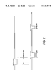
- FIG. 5 is a flow diagram illustrating the operation of the system.
- the printing machine of the present invention uses a charge retentive surface in the form of an Active Matrix (AMAT) photoreceptor belt 10 supported for movement in the direction indicated by arrow 12 , for advancing sequentially through the various xerographic process stations.
- the belt is entrained about a drive roller 14 , tension rollers 16 and fixed roller 18 and the roller 14 is operatively connected to a drive motor 20 for effecting movement of the belt through the xerographic stations.
- AMAT Active Matrix
- a portion of belt 10 passes through charging station A where a corona generating device, indicated generally by the reference numeral 22 , charges the photoconductive surface of belt 10 to a relatively high, substantially uniform, preferably negative potential.
- a controller indicated generally by reference numeral 90 , receives the image signals from controller 100 representing the desired output image and processes these signals to convert them to the various color separations of the image which is transmitted to a laser based output scanning device 24 which causes the charge retentive surface to be discharged in accordance with the output from the scanning device.
- the scanning device is a laser Raster Output Scanner (ROS).
- ROS Raster Output Scanner
- the ROS could be replaced by other xerographic exposure devices such as LED arrays.
- the photoreceptor which is initially charged to a voltage V O , undergoes dark decay to a level V ddp equal to about ⁇ 500 volts. When exposed at the exposure station B it is discharged to V expose equal to about ⁇ 50 volts. Thus after exposure, the photoreceptor contains a monopolar voltage profile of high and low voltages, the former corresponding to charged areas and the latter corresponding to discharged or background areas.
- developer structure indicated generally by the reference numeral 32 utilizing a hybrid jumping development (HJD) system
- the development roll is powered by two development fields (potentials across an air gap).
- the first field is the ac jumping field which is used for toner cloud generation.
- the second field is the dc development field which is used to control the amount of developed toner mass on the photoreceptor.
- the toner cloud causes charged toner particles 26 to be attracted to the electrostatic latent image.
- Appropriate developer biasing is accomplished via a power supply.
- This type of system is a noncontact type in which only toner particles (black, for example) are attracted to the latent image and there is no mechanical contact between the photoreceptor and a toner delivery device to disturb a previously developed, but unfixed, image.
- the developed but unfixed image is then transported past a second charging device 36 where the photoreceptor and previously developed toner image areas are recharged to a predetermined level.
- a second exposure/imaging is performed by device 38 which comprises a laser based output structure is utilized for selectively discharging the photoreceptor on toned areas and/or bare areas, pursuant to the image to be developed with the second color toner.
- the photoreceptor contains toned and untoned areas at relatively high voltage levels and toned and untoned areas at relatively low voltage levels. These low voltage areas represent image areas which are developed using discharged area development (DAD).
- DAD discharged area development
- a negatively charged, developer material 40 comprising color toner is employed.
- the toner which by way of example may be yellow, is contained in a developer housing structure 42 disposed at a second developer station D and is presented to the latent images on the photoreceptor by way of a second HJD developer system.
- a power supply (not shown) serves to electrically bias the developer structure to a level effective to develop the discharged image areas with negatively charged yellow toner particles 40 .
- the above procedure is repeated for a third image for a third suitable color toner such as magenta and for a fourth image and suitable color toner such as cyan at stations E and F, respectively.
- the exposure control scheme described below may be utilized for these subsequent imaging steps. In this manner a full color composite toner image is developed on the photoreceptor belt.
- the timing of the various imaging stations is sensed and controlled by the system as described below.
- a negative pre-transfer dicorotron member 50 is provided to condition the toner for effective transfer to a substrate using positive corona discharge.
- a sheet of support material 52 is moved into contact with the toner images at transfer station G.
- the sheet of support material is advanced to transfer station G by the sheet feeding apparatus 200 .
- the sheet of support material is then brought into contact with photoconductive surface of belt 10 in a timed sequence so that the toner powder image developed thereon contacts the advancing sheet of support material at transfer station G.
- Transfer station G includes a transfer dicorotron 54 which sprays positive ions onto the backside of sheet 52 . This attracts the negatively charged toner powder images from the belt 10 to sheet 52 .
- a detack dicorotron 56 is provided for facilitating stripping of the sheets from the belt 10 .
- Fusing station H includes a fuser assembly, indicated generally by the reference numeral 60 , which permanently affixes the transferred powder image to sheet 52 .
- fuser assembly 60 comprises a heated fuser roller 62 and a backup or pressure roller 64 .
- Sheet 52 passes between fuser roller 62 and backup roller 64 with the toner powder image contacting fuser roller 62 . In this manner, the toner powder images are permanently affixed to sheet 52 .
- a chute guides the advancing sheets 52 to a catch tray, stacker, finisher or other output device (not shown), for subsequent removal from the printing machine by the operator.
- the residual toner particles carried by the non-image areas on the photoconductive surface are removed therefrom. These particles are removed at cleaning station I using a cleaning brush or plural brush structure contained in a housing 66 .
- image on image (IOI) single pass xerographic engines are designed such that different colors are laid on top of each other, all in one pass of the photoreceptor (P/R) belt 10 .
- each color has its own image station that consists of a charge device, raster output scanner (ROS), (determines how the latent image appears on the P/R belt), a developer (applies the colored toner to the latent image on the belt) and a belt hole sensor which signals the ROS to begin to lay the image. Therefore, if an IOI single pass engine applies four colors, there will be four image stations, each consisting of a charge device, ROS, developer and belt hole sensor.
- ROS raster output scanner
- the ROS needs some timing signal to apply the latent image at the right time for its respective color.
- this signal has been provided by holes on the edge of the photoreceptor belt.
- the belt hole sensor for that image station provides a signal for the ROS to begin writing the latent image on the belt.
- the first hole is larger than the others (this can be detected by the belt hole sensor signal) and signifies the location of the seam on the belt.
- the problem with this design is that the belt must be changed when pitch mode is changed; e.g. 8 pitch mode requires only 8 holes and the holes would be separated differently than a 10 pitch mode belt.
- this design requires four separate sensors—one for each image station.
- the virtual belt hole system is capable of generating belt holes for 4 to 25 pitch modes and its only limitation for even higher pitch modes is microprocessor capability.
- this algorithm there is only one hole required on the belt, the seam hole. All other holes are generated by VBH system electronically. Also there is only one sensor required with this design.
- the virtual belt holes that are generated by the VBH system look the same as a signal that would be generated by a sensor that sensed a real belt hole as it passed by at process speed. Moreover, the belt holes that are generated by the VBH system are more precise than those generated by a typical sensor reading a hole as the belt passes. In summary, this method uses one belt for any one of seven pitch modes as opposed to 7 different belts for 7 different pitch modes. The signals are more precise and only one belt hole sensor is required with VBH as opposed to 4 without it.
- the virtual belt holes are created by the VBH system.
- the VBH system is a part of the overall P/R belt drive control system which also controls the speed and steering functions of the P/R belt.
- the printed wire board assembly (PWBA) of the preferred embodiment consists of a microprocessor which is programmed with firmware, however, it is also possible to perform the same function with a software application.
- the board also has hardware to read inputs into the microprocessor and hardware to allow the microprocessor to produce outputs.
- a photoreceptor encoder and a seam hole signal are two inputs to the P/R PWBA that are used for belt control system.
- the virtual belt hole system makes use of these pre-existing signals:
- Encoder feedback The encoder 80 is attached to a roll on the photoreceptor and is used for motion control algorithms.
- the virtual belt hole system uses this signal 82 for position feedback.
- the seam hole provides once around feedback for motion control systems.
- the virtual belt hole system uses this signal for reference to count encoder signals. It also is the key to determining where the belt holes will be generated since imaging can not take place near the belt seam.
- the VBH system makes use of signals that are already required by the P/R PWBA.
- the Virtual Belt Hole (VBH) system was designed to require as few download parameters as possible.
- the following table lists the required parameters that need to be downloaded to initialize the image sync generation (VBH). After initialization, only three parameters (Seam_To_Image2, Images_Per_Rev, and Image_To_Image) require update for each change in pitch on the photoreceptor belt. Seam to image 1 and seam to image 2 are unique distances, only seam to image two will change for new pitch modes.
- the VBH system is designed to be transparent to a 10-hole belt but provide programmability to other pitches.
- Seam_Hole_time is the value of a counter when the last seam occurred. It is clocked by the P/R encoder which provides a rate of ⁇ 0.15 mm/count. It is used as a reference point for one belt revolution. Seam_Hole_time is buffered (maximum of 2) for a belt revolution since a new seam hole event may occur on image station 1 while image station 4 has not yet completed the prior belt rev. This insures that all image syncs on a belt rev are referenced to the same point.
- the first belt hole at each image station will be the equivalent of a seam hole in length 6 mm by default (12.8 ms @100 ppm).
- LeadEdge 1 Seam_To_RosN+Seam_Hole_time+Seam_To_Image1
- TrailEdge 1 LeadEdge 1 +Seam_Hole_Length
- LeadEdge 2 Seam_To_RosN+Seam_Hole_Time+Seam_To_Image2
- TrailEdge 2 LeadEdge 2 +Belt_Hole_Length
- TrailEdge(X) LeadEdge(X)+Belt_Hole_Length
- FIG. 5 illustrates a flow diagram for the system operation at the first imaging station.
- a system for controlling the imaging device in a single pass multi color electrophotographic printing machine comprising a photoconductive member defining a timing aperture, the member moving along a path in a printing machine and a plurality of imaging devices, each one of the plurality of imaging devices writing a latent image on the photoconductive member.
- the system further includes a sensor, located adjacent the photoconductive member, to sense the aperture in the photoconductive member as it passes the sensor and generate a signal indicative thereof and a control device, which generates a timing signal for each of the plurality of imaging devices as a function of the signal generated by the sensor and a plurality of predetermined parameters.
Landscapes
- Physics & Mathematics (AREA)
- General Physics & Mathematics (AREA)
- Control Or Security For Electrophotography (AREA)
- Color Electrophotography (AREA)
- Dot-Matrix Printers And Others (AREA)
- Fax Reproducing Arrangements (AREA)
- Color, Gradation (AREA)
- Laser Beam Printer (AREA)
Priority Applications (6)
| Application Number | Priority Date | Filing Date | Title |
|---|---|---|---|
| US09/471,863 US6181887B1 (en) | 1999-12-23 | 1999-12-23 | Control system utilizing virtual belt holes |
| CA002327036A CA2327036C (en) | 1999-12-23 | 2000-11-29 | Control system utilizing virtual belt holes |
| JP2000374142A JP2001337508A (ja) | 1999-12-23 | 2000-12-08 | 電子写真制御システム及び画像形成制御方法 |
| DE60017064T DE60017064T2 (de) | 1999-12-23 | 2000-12-11 | Steuerungssytem für Druckmaschine |
| EP00311036A EP1111476B1 (de) | 1999-12-23 | 2000-12-11 | Steuerungssytem für Druckmaschine |
| BR0006279-0A BR0006279A (pt) | 1999-12-23 | 2000-12-22 | Sistema de controle que utiliza orifìcios de correia virtuais |
Applications Claiming Priority (1)
| Application Number | Priority Date | Filing Date | Title |
|---|---|---|---|
| US09/471,863 US6181887B1 (en) | 1999-12-23 | 1999-12-23 | Control system utilizing virtual belt holes |
Publications (1)
| Publication Number | Publication Date |
|---|---|
| US6181887B1 true US6181887B1 (en) | 2001-01-30 |
Family
ID=23873279
Family Applications (1)
| Application Number | Title | Priority Date | Filing Date |
|---|---|---|---|
| US09/471,863 Expired - Lifetime US6181887B1 (en) | 1999-12-23 | 1999-12-23 | Control system utilizing virtual belt holes |
Country Status (6)
| Country | Link |
|---|---|
| US (1) | US6181887B1 (de) |
| EP (1) | EP1111476B1 (de) |
| JP (1) | JP2001337508A (de) |
| BR (1) | BR0006279A (de) |
| CA (1) | CA2327036C (de) |
| DE (1) | DE60017064T2 (de) |
Cited By (2)
| Publication number | Priority date | Publication date | Assignee | Title |
|---|---|---|---|---|
| US20050249513A1 (en) * | 2004-05-05 | 2005-11-10 | Eastman Kodak Company | Apparatus and process for altering timing in an electrographic printer |
| US7298998B1 (en) | 2006-06-26 | 2007-11-20 | Xerox Corporation | Image registration control utilizing real time image synchronization |
Families Citing this family (2)
| Publication number | Priority date | Publication date | Assignee | Title |
|---|---|---|---|---|
| US6498913B1 (en) * | 2001-08-27 | 2002-12-24 | Xerox Corporation | Static charge controlling system and a reproduction machine having same |
| US8295749B2 (en) * | 2010-06-02 | 2012-10-23 | Xerox Corporation | Method and apparatus for printing various sheet sizes within a pitch mode in a digital printing system |
Citations (2)
| Publication number | Priority date | Publication date | Assignee | Title |
|---|---|---|---|---|
| US5291245A (en) * | 1993-03-23 | 1994-03-01 | Xerox Corporation | Photoreceptor belt seam detection and process control |
| US5784676A (en) * | 1995-04-14 | 1998-07-21 | Fuji Xerox Co., Ltd. | Roller for belt transporting apparatus and image forming apparatus |
Family Cites Families (3)
| Publication number | Priority date | Publication date | Assignee | Title |
|---|---|---|---|---|
| US4914477A (en) * | 1988-11-14 | 1990-04-03 | Eastman Kodak Company | Reproduction apparatus having an image member with timing indicia |
| US5121145A (en) * | 1990-08-03 | 1992-06-09 | Eastman Kodak Company | Line printhead device for nonimpact printer |
| US5342715A (en) * | 1993-04-23 | 1994-08-30 | Xerox Corporation | Color printer having reduced first copy out time and extended photoreceptor life |
-
1999
- 1999-12-23 US US09/471,863 patent/US6181887B1/en not_active Expired - Lifetime
-
2000
- 2000-11-29 CA CA002327036A patent/CA2327036C/en not_active Expired - Fee Related
- 2000-12-08 JP JP2000374142A patent/JP2001337508A/ja active Pending
- 2000-12-11 DE DE60017064T patent/DE60017064T2/de not_active Expired - Lifetime
- 2000-12-11 EP EP00311036A patent/EP1111476B1/de not_active Expired - Lifetime
- 2000-12-22 BR BR0006279-0A patent/BR0006279A/pt not_active Application Discontinuation
Patent Citations (2)
| Publication number | Priority date | Publication date | Assignee | Title |
|---|---|---|---|---|
| US5291245A (en) * | 1993-03-23 | 1994-03-01 | Xerox Corporation | Photoreceptor belt seam detection and process control |
| US5784676A (en) * | 1995-04-14 | 1998-07-21 | Fuji Xerox Co., Ltd. | Roller for belt transporting apparatus and image forming apparatus |
Cited By (3)
| Publication number | Priority date | Publication date | Assignee | Title |
|---|---|---|---|---|
| US20050249513A1 (en) * | 2004-05-05 | 2005-11-10 | Eastman Kodak Company | Apparatus and process for altering timing in an electrographic printer |
| US7343108B2 (en) | 2004-05-05 | 2008-03-11 | Eastman Kodak Company | Apparatus and process for altering timing in an electrographic printer |
| US7298998B1 (en) | 2006-06-26 | 2007-11-20 | Xerox Corporation | Image registration control utilizing real time image synchronization |
Also Published As
| Publication number | Publication date |
|---|---|
| EP1111476B1 (de) | 2004-12-29 |
| CA2327036A1 (en) | 2001-06-23 |
| DE60017064T2 (de) | 2005-05-25 |
| DE60017064D1 (de) | 2005-02-03 |
| BR0006279A (pt) | 2001-09-25 |
| CA2327036C (en) | 2002-10-01 |
| EP1111476A2 (de) | 2001-06-27 |
| JP2001337508A (ja) | 2001-12-07 |
| EP1111476A3 (de) | 2002-08-21 |
Similar Documents
| Publication | Publication Date | Title |
|---|---|---|
| KR100299640B1 (ko) | 정전사식단일-패스다단프린터 | |
| EP0298506B1 (de) | Bilderzeugungsgerät | |
| JP3009995B2 (ja) | 位置合わせ制御を有する静電写真式1パス型マルチステーションプリンタ | |
| US4963899A (en) | Method and apparatus for image frame registration | |
| KR100310589B1 (ko) | 양면인쇄용정전사진식단일-패스다중스테이션프린터 | |
| EP2541892B1 (de) | Farbbilderzeugungsvorrichtung | |
| JP3399492B2 (ja) | ベルト駆動制御装置 | |
| US8570587B2 (en) | Method and apparatus for accurate measurement of imaging surface speed in a printing apparatus | |
| JPH11218977A (ja) | プリント装置におけるプリントプロセスの制御方法 | |
| US7720401B2 (en) | Inter-document zone gloss defect eliminator | |
| JP3132534B2 (ja) | 画像形成装置の画像濃度制御方法 | |
| EP0715224B1 (de) | Verfahren und Vorrichtung zur Erzeugung von mehreren Bildern | |
| CN100357839C (zh) | 图像形成装置 | |
| US6498909B1 (en) | Method and apparatus for controlling the toner concentration in an electrographic process | |
| EP1705896A2 (de) | Verfahren und System für Rasterausgabeabtaststeuerung eines elektrofotografischen Systems | |
| US8099009B2 (en) | Method for print engine synchronization | |
| US6393244B1 (en) | Color shift correcting structure of image forming apparatus | |
| US6181887B1 (en) | Control system utilizing virtual belt holes | |
| US8180242B2 (en) | Print engine synchronization system and apparatus | |
| US7298998B1 (en) | Image registration control utilizing real time image synchronization | |
| EP0531053B1 (de) | Dreistufiges Bilderzeugungsgerät | |
| US8180266B2 (en) | Method, apparatus and systems for registering the transfer of an image associated with a printing device | |
| US6456309B1 (en) | Color image registration based upon belt and raster output scanner synchronization | |
| JPH09127847A (ja) | カラーレーザプリンタ | |
| JPH08224912A (ja) | カラープリンタ |
Legal Events
| Date | Code | Title | Description |
|---|---|---|---|
| AS | Assignment |
Owner name: XEROX CORPORATION, CONNECTICUT Free format text: ASSIGNMENT OF ASSIGNORS INTEREST;ASSIGNORS:HUGHES, DAVID A.;MONAHAN, MICHAEL B.;LACAYO, ORLANDO J.;REEL/FRAME:010695/0905 Effective date: 20000222 |
|
| STCF | Information on status: patent grant |
Free format text: PATENTED CASE |
|
| AS | Assignment |
Owner name: BANK ONE, NA, AS ADMINISTRATIVE AGENT, ILLINOIS Free format text: SECURITY INTEREST;ASSIGNOR:XEROX CORPORATION;REEL/FRAME:013153/0001 Effective date: 20020621 |
|
| AS | Assignment |
Owner name: JPMORGAN CHASE BANK, AS COLLATERAL AGENT, TEXAS Free format text: SECURITY AGREEMENT;ASSIGNOR:XEROX CORPORATION;REEL/FRAME:015134/0476 Effective date: 20030625 Owner name: JPMORGAN CHASE BANK, AS COLLATERAL AGENT,TEXAS Free format text: SECURITY AGREEMENT;ASSIGNOR:XEROX CORPORATION;REEL/FRAME:015134/0476 Effective date: 20030625 |
|
| FPAY | Fee payment |
Year of fee payment: 4 |
|
| FPAY | Fee payment |
Year of fee payment: 8 |
|
| FPAY | Fee payment |
Year of fee payment: 12 |
|
| AS | Assignment |
Owner name: XEROX CORPORATION, NEW YORK Free format text: RELEASE BY SECURED PARTY;ASSIGNOR:BANK ONE, NA;REEL/FRAME:034717/0200 Effective date: 20030625 Owner name: XEROX CORPORATION, NEW YORK Free format text: RELEASE BY SECURED PARTY;ASSIGNOR:JPMORGAN CHASE BANK, N.A.;REEL/FRAME:034715/0792 Effective date: 20061204 |
|
| AS | Assignment |
Owner name: XEROX CORPORATION, CONNECTICUT Free format text: RELEASE BY SECURED PARTY;ASSIGNOR:JPMORGAN CHASE BANK, N.A. AS SUCCESSOR-IN-INTEREST ADMINISTRATIVE AGENT AND COLLATERAL AGENT TO JPMORGAN CHASE BANK;REEL/FRAME:066728/0193 Effective date: 20220822 |