US6176898B1 - Method and system for collecting and handling dust in a papermachine environment - Google Patents
Method and system for collecting and handling dust in a papermachine environment Download PDFInfo
- Publication number
- US6176898B1 US6176898B1 US09/289,411 US28941199A US6176898B1 US 6176898 B1 US6176898 B1 US 6176898B1 US 28941199 A US28941199 A US 28941199A US 6176898 B1 US6176898 B1 US 6176898B1
- Authority
- US
- United States
- Prior art keywords
- collector
- dust
- air
- inlet
- laden air
- Prior art date
- Legal status (The legal status is an assumption and is not a legal conclusion. Google has not performed a legal analysis and makes no representation as to the accuracy of the status listed.)
- Expired - Lifetime
Links
- 239000000428 dust Substances 0.000 title claims abstract description 82
- 238000000034 method Methods 0.000 title claims abstract description 24
- XLYOFNOQVPJJNP-UHFFFAOYSA-N water Substances O XLYOFNOQVPJJNP-UHFFFAOYSA-N 0.000 claims abstract description 79
- 230000008569 process Effects 0.000 claims abstract description 16
- 230000006872 improvement Effects 0.000 claims description 11
- 230000000694 effects Effects 0.000 claims 1
- 230000001939 inductive effect Effects 0.000 claims 1
- 238000005200 wet scrubbing Methods 0.000 description 8
- 239000000203 mixture Substances 0.000 description 5
- 239000002245 particle Substances 0.000 description 5
- 230000009471 action Effects 0.000 description 3
- 238000004140 cleaning Methods 0.000 description 3
- 230000003749 cleanliness Effects 0.000 description 3
- 239000012634 fragment Substances 0.000 description 3
- 229920003043 Cellulose fiber Polymers 0.000 description 2
- 229920002472 Starch Polymers 0.000 description 2
- 238000009825 accumulation Methods 0.000 description 2
- 230000002411 adverse Effects 0.000 description 2
- 239000004927 clay Substances 0.000 description 2
- 239000000383 hazardous chemical Substances 0.000 description 2
- 231100000206 health hazard Toxicity 0.000 description 2
- 238000000926 separation method Methods 0.000 description 2
- 239000008107 starch Substances 0.000 description 2
- 235000019698 starch Nutrition 0.000 description 2
- 239000000126 substance Substances 0.000 description 2
- 230000001629 suppression Effects 0.000 description 2
- 230000000740 bleeding effect Effects 0.000 description 1
- 238000010276 construction Methods 0.000 description 1
- 230000003247 decreasing effect Effects 0.000 description 1
- 239000000284 extract Substances 0.000 description 1
- 230000005484 gravity Effects 0.000 description 1
- 238000009434 installation Methods 0.000 description 1
- 238000005304 joining Methods 0.000 description 1
- 238000004519 manufacturing process Methods 0.000 description 1
- 238000012986 modification Methods 0.000 description 1
- 230000004048 modification Effects 0.000 description 1
- 230000002265 prevention Effects 0.000 description 1
- 230000001902 propagating effect Effects 0.000 description 1
- 230000009467 reduction Effects 0.000 description 1
- 239000007921 spray Substances 0.000 description 1
- 230000003068 static effect Effects 0.000 description 1
- 238000006467 substitution reaction Methods 0.000 description 1
Images

Classifications
-
- B—PERFORMING OPERATIONS; TRANSPORTING
- B01—PHYSICAL OR CHEMICAL PROCESSES OR APPARATUS IN GENERAL
- B01D—SEPARATION
- B01D45/00—Separating dispersed particles from gases or vapours by gravity, inertia, or centrifugal forces
- B01D45/12—Separating dispersed particles from gases or vapours by gravity, inertia, or centrifugal forces by centrifugal forces
-
- B—PERFORMING OPERATIONS; TRANSPORTING
- B01—PHYSICAL OR CHEMICAL PROCESSES OR APPARATUS IN GENERAL
- B01D—SEPARATION
- B01D47/00—Separating dispersed particles from gases, air or vapours by liquid as separating agent
- B01D47/06—Spray cleaning
-
- D—TEXTILES; PAPER
- D21—PAPER-MAKING; PRODUCTION OF CELLULOSE
- D21F—PAPER-MAKING MACHINES; METHODS OF PRODUCING PAPER THEREON
- D21F5/00—Dryer section of machines for making continuous webs of paper
-
- D—TEXTILES; PAPER
- D21—PAPER-MAKING; PRODUCTION OF CELLULOSE
- D21G—CALENDERS; ACCESSORIES FOR PAPER-MAKING MACHINES
- D21G3/00—Doctors
Definitions
- This invention relates generally to the collection and handling of dust and more particularly is concerned with the means and methods for collecting dust in the environment of a papermaking machine and for transporting the dust from the machine environment after the dust has been collected.
- a relatively large amount of dust may be released into the surrounding air by the papermaking process, and this released dust can create operating hazards, worker health hazards, and is likely to migrate to various areas of the room and create a cleanliness (e.g. machine hygiene) problem or increase the risk of fire at those areas.
- attempts to control the amount of dust released into a papermaking machine room involved the capturing of dust adjacent the source of creation (referred to herein as primary dust control) and the containing of dust after the dust has become airborne (referred to herein as secondary dust control).
- the systems and methods with which this invention is to be compared include the systems and methods employed for primary dust control and for secondary dust control.
- Conventional primary and secondary dust control schemes commonly involve a fan or similar means for creating a vacuum at a collector, or vacuum head, through which dust and/or dust-laden air is drawn into the interior of the collector and subsequently transported from the collector by way of attending ductwork.
- a fan or similar means for creating a vacuum at a collector, or vacuum head, through which dust and/or dust-laden air is drawn into the interior of the collector and subsequently transported from the collector by way of attending ductwork.
- relatively high transport velocities are employed within the ductwork.
- wet-scrubbing equipment is commonly connected to the ductwork at a site downstream of the collector for wet-scrubbing the dust-laden air in a manner which separates dust from the air so that the air which is subsequently discharged to the atmosphere is relatively clean.
- Limitations and disadvantages attending the conventional primary and secondary dust control schemes of the aforedescribed class relate to system operation, safety from fires, and cost.
- the likelihood is high that the ductwork through which the dust and dust-laden air is transported will become fouled, or clogged, with dust so that design volumetric flow rates cannot be maintained.
- the cleanliness of the interior of the collectors and the attending ductwork can be adversely affected by moisture present within the dust-laden airstream. Low moisture levels will cause the dry dust particles to attach themselves to each other and/or the interior surface of the ductwork.
- Low moisture levels in the airstream are typically caused by intermittent introduction of water or high humidity levels at the inlet of the collector. Further still, water may be inadvertently and intermittently introduced into the inlets of the collectors during a cleanup operation performed around the machine. Consequently, the collectors and attending ductwork of these conventional dust control schemes require frequent and costly cleaning.
- ductwork fouling in conjunction with the high air flows, creates a situation in which a fire, if ignited (e.g. by mechanical friction or static charges) and not extinguished immediately, could propagate and damage components throughout the system, as well as present a high risk to human safety.
- Fire suppression equipment can be installed within the system to reduce the damage and safety risks of ductwork fires, but such equipment is relatively expensive, is rarely one-hundred percent effective, and must be routinely maintained in order to preserve the operating effectiveness that it possesses.
- wet-scrubbing equipment which is commonly employed with conventional dust control systems is relatively expensive, and its cost, along with the cost of associated access platforms, support structures and installation, is likely to comprise a significant portion of the capital cost of the entire dust-collection system.
- Another object of the present invention is to provide such a means and method which can be used for either primary or secondary dust control.
- Still another object of the present invention is to provide such a means and method which reduces the likelihood of ductwork fouling, reduces the risk of a ductwork fire, and obviates the need for costly fire suppression equipment.
- Yet another object of the present invention is to provide such a means and method which permits the relatively costly wet-scrubbing equipment to be replaced with a less costly droplet separator.
- a further object of the present invention is to provide such a means which is uncomplicated in construction yet effective in operation.
- This invention resides in a improved process and system for collecting and handling dust in a papermaking environment wherein dust-laden air is drawn into and moves along an elongated collector by way of a vacuum-generating source connected to the collector.
- the improvement of the process includes a step of introducing water into the collector so that the introduced water wet-scrubs the dust-laden air upon entering the collector, and the improvement of the system includes means for introducing the water into the collector.
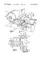
- FIG. 1 is a perspective view of a fragment of a papermaking machine with which an embodiment of a dust collection and handling system is, employed.
- FIG. 2 is a cross-sectional view of a fragment of the FIG. 1 papermaking machine as viewed generally along line 2 — 2 of FIG. 1 and schematically illustrating the operating components of the dust collection and handling system employed with the FIG. 1 machine.
- FIG. 3 is a perspective view, shown partially in section, of one of the collectors of the dust collecting and handling system of FIG. 2 .
- FIG. 4 is a radial cross-sectional view of the collector of FIG. 3 .
- FIG. 5 is a perspective view illustrating the helical flow of dust and water along the length of the collector of FIG. 3 during a dust-collecting operation.
- FIGS. 1 and 2 there is shown a typical environment, generally indicated 20 , within which a dust collecting and handling system, generally indicated 22 , is employed to carry out an embodiment of the process of the present invention.
- the environment 20 is that of a papermaking machine room within which a papermaking machine 24 is housed.
- the depicted papermaking machine 24 is a tissue-making machine including a series of rotating drums 26 (only one shown in FIGS. 1 and 2) across which a moving web 28 of tissue paper is routed before being wound about a roll 30 and is known to generate a relatively large amount of dust (including cellulose fiber, clay, starch and other chemical dust) during its operation.
- this dust could create operating hazeards, worker health hazards, and could migrate to various areas of the room and create a cleanliness (e.g. machine hygiene) problem or increase the risk of fire at those areas.
- the dust collecting and handling system 22 acts in a primary dust control capacity for collecting dust directly from the surface of the moving web 28 (e.g. a site from which a large amount of dust could otherwise be released into the surrounding air) and in a secondary dust control capacity for containing and collecting dust after it has become airborne.
- a canopy hood 36 is supported about so as to envelope the end of the moving web 28 adjacent the roll 30 and thereby substantially confine the air disposed in the vicinity of the roll-end of the moving web 28 . It is from within this confined area, indicated 32 , that the system 22 extracts dust and dust-laden air for subsequent handling.
- the system 22 includes a pair of collectors 38 , 40 , means, indicated 42 , for generating a vacuum within the interior of the collectors 38 , 40 so that dust and dust-laden air is drawn into the interior of the collectors 38 , 40 from the confined area 32 , and attending ductwork 44 joining the collectors 38 , 40 and the vacuum-generating source 42 .
- the vacuum-generating source 42 includes a motor-driven centrifugal fan 46 connected within the ductwork 44 at a location downstream of the collectors 38 , 40 .
- the ductwork 44 appropriately connects the collectors 38 (which are arranged in parallel) to the inlet (i.e. low-pressure side) of the fan 46 so that during fan operation, the interiors of the collectors 38 , 40 are exposed to the low pressure created at the fan inlet.
- each collector 38 or 40 is substantially rounded in form having a cylindrical body portion 51 and is elongated in shape having two opposite ends 48 and 50 . Furthermore, each collector 38 or 40 is substantially circular in cross section so as to provide each collector with smooth, round interior walls and includes a V-shaped inlet portion 52 joined to the body portion 51 so as to extend along a side of the pipe 38 or 40 .
- the V-shaped inlet portion 52 includes two planar legs 54 and 56 which are joined at an apex 53 which is directed inwardly of the collector 38 or 40 , and a continuous slot-like inlet opening 58 is defined in one of the legs 56 to provide an inlet for the collector which extends along the entire collector length.
- the inlet 58 opens somewhat tangentially along the interior of the collector, rather than radially inwardly toward the longitudinal axis of the collector.
- the drawing of air through one end of the collector by the fan 46 in conjunction with this canted orientation of the collector inlet 58 induces a vortex, or helical flow, of air along the length of the collector as air is pulled into the collector interior through the inlet 58 .
- the inlet 58 is bounded by relatively sharp edges to provide a good wet/dry interface and thus reduce any likelihood that dust will accumulate along the inlet edges and thereby clog the inlet 58 .
- each collector 38 or 40 can be provided with an overhang portion 60 disposed adjacent the inlet 58 as shown in FIG. 3, and each collector 38 or 40 can be provided with an inlet guard assembly 61 which is comprised of a plurality of vertically-oriented rods 62 arranged parallel to one another and connected to a common horizontal member 63 which is joined to the overhang portion 60 so at to be oriented generally parallel to the longitudinal axis of the collector.
- These rods 62 are fixedly secured at the tops thereof to the horizontal member 63 so as to be spaced forwardly of the inlet 58 (in a region of lower-velocity air flow) and serve to restrict the intake of broke (e.g.
- the vertical rods 62 are not supported or attached at the lower ends so that these lower ends are out of contact with the remainder of the collector. This feature allows broke to easily dislodge and freely fall, under the influence of gravity, from the inlet guard assembly 61 .
- the guard assembly 61 can be pivotally attached to the overhang 60 to permit the lower ends of the rods 62 of the guard assembly 61 to be manually moved (i.e. swung) about the longitudinal axis of the horizontal member 63 and in a direction forwardly of the inlet 58 .
- each collector 38 or 40 is suitably supported within the confined area 32 (FIG. 1) in a horizontal orientation and at locations therein at which one collector 38 draws dust directly from the surface of the moving web 28 of paper and at which the other collector 40 draws dust-laden air from beneath the canopy hood 36 . Consequently, the collector 38 is used in a primary dust control capacity in that it is used to draw dust from a site in the papermachine 24 from which the dust may otherwise become airborne and contaminate the surrounding air, while the other collector 40 is used in a secondary dust control capacity in that it is used collect dust after the dust has become airborne.
- the collector 38 is supported across the moving web 28 so that its inlet 58 is directed generally downwardly toward and is disposed in close proximity to the web 28 , while the collector 40 is supported in an elevated condition appreciably above the surface of the web 28 .
- the position of the inlet 58 of the collector 40 is not as critical as it is in the case of the collector 38 , it is preferable that the collector 40 is oriented so that its inlet 58 opens in a direction so that air flow currents induced within the confined area naturally carry the dust, and dust-laden air, toward the inlet 58 .
- the ductwork 44 is connected to the end 50 of each collector 38 and 40 so that air and dust particles which are drawn into the collector move generally along the interior of the collector 38 or 40 from the end 48 thereof toward the end 50 thereof.
- the drawing of the air out of the collector 38 or 40 in conjunction with the canted orientation of the collector inlet 58 , pulls dust and air into the interior of the collector through the inlet 58 thereof and induces a vortex of air through the collector interior which moves generally toward the end 50 thereof.
- the air enters the collector substantially tangentially with respect thereto and subsequently spirals along the interior walls of the collector toward the collector end 50 .
- an air vortex is induced within the collector wherein the air vortex rotates about the longitudinal axis of the collector and converges toward the collector end 50 .
- the flow of this induced vortex along the interior walls of the collector is not appreciably (e.g. adversely) affected by the inwardly-directed inlet portion 52 .
- the system 22 includes a water supply 70 , including a tank 71 , which is connected to the collector ends 48 by way of an inlet conduit 72 . As best shown in FIG.
- the conduit 72 is provided with two branch conduits 72 a and 72 b which are joined to the collectors 38 , 40 so that water which is introduced into each collector enters the collector substantially tangentially thereof along an interior wall.
- the direction of the water introduced through the conduits 72 a , 72 b corresponds generally with the direction of movement of air along the interior wall of the collector.
- Water is forcibly moved along the inlet conduits 72 by way of a motor-driven pump 74 (FIG. 2) mounted adjacent the base of the supply tank 70 .
- the flow rate of water through the conduit 72 can be controlled by appropriate adjustment of the speed of the pump 74 or by appropriate adjustment of control/shut-off valves 76 , 78 mounted in the branch conduits 72 a , 72 b adjacent the collector ends 48 .
- An additional conduit 84 within which is mounted a bleed valve 86 , is joined to the inlet conduit 72 at a location downstream of the pump 74 to accommodate the bleeding or draining of water from the conduit 72 .
- each collector end 48 Upon introduction of the water into each collector end 48 during operation of the fan 46 (so that water is introduced into the collector while dust and air is being drawn into the collector through the inlet 58 thereof), the water becomes entrained within the dust-laden air and transported along the collector within the induced air vortex. The majority of the water rotates about the longitudinal axis of the collector and is forced to sweep across the interior side of the collector inlet 58 in a swirling action and collide with the dust-laden air drawn into the collector through the inlet 58 .
- the aforedescribed movement of the air and water through the collector serves the purpose of wet-scrubbing the 25 dust-laden air moving through the collector and forces water to flow in a spiraling path, or swirl, along the interior walls of the collector for the entire length thereof.
- wet-scrubbing means to encapsulate dust particles with water for subsequent separation of the dust-laden water from the airstream. Consequently, upon arriving at the collector end 50 by way of the collector interior, most of the dust of the dust-laden air has been thoroughly wetted by the introduced water.
- the interior of the collector is continually rinsed by the movement of the water swirling along the walls of the collector with the air vortex so that the collector interior is thereby maintained in a relatively clean condition.
- the amount of water which is introduced into the collector at the end 48 thereof is coordinated with the flow of air drawn through the collector by the fan 46 so that the amount of introduced water is sufficient to thoroughly wet, or scrub, all of the dust-laden air transported along the collector before it exits the collector end 50 yet is not so large that the capacity of the collector to draw dust and air through the inlet 58 is appreciably affected.
- a drain port 90 through which much of the water which exits the collectors 38 and 40 can be drained.
- the port go is disposed at an elevation lower than that of the collector ends 50 and the remainder of the ductwork 44 so that water which is not entrained within the air/water mixture carried toward the fan 46 can be routed directly back to the supply tank 70 by way of a conduit 92 .
- another inlet conduit 94 is joined to the ductwork 44 at a location elevated above the collector ends 50 for introducing water, in a spray, into the ductwork 44 thereat.
- This conduit 94 is not connected to the pump 74 , but receives water from another source, such as a utility supply, for providing the system 22 with make-up water through a valve 82 .
- the water which is introduced into the ductwork 44 through the conduit 94 and which does not become entrained by the air moving toward the fan 46 is permitted to collect at the port 90 for subsequent draining from the ductwork 44 .
- a droplet separator unit 98 for separating the (dust-carrying) water from the air/water mixture moving toward the fan 46 .
- the structure and operation of the separator unit 98 are well-known that a complete description of the unit 98 is not believed to be necessary. Suffice it to say that the unit 98 includes internal ductwork which possess a larger diameter than that of the ductwork 44 which leads to the unit 98 so as the air/water mixture enters the unit 98 , its velocity is suddenly decreased and this reduction of velocity permits the water to fall out of the air and accumulate at the bottom of the unit 98 .
- the air which is rendered substantially water-free by the unit 98 , continues to be drawn along the ductwork 44 and out of the unit 98 by the fan 46 for discharge into the environment—preferably outside of the papermaking plant.
- Water which collects in the bottom of the unit 98 can be drained to the supply tank 70 by way of discharge conduit 100 which extends between the bottom of the unit 98 and the top of the supply tank 70 . It can be seen from the FIG. 2 view that due to the recirculation of water back to the supply tank 70 for re-introduction into the collector ends 48 , a majority of the water of the system 22 operates in a closed-loop.
- the aforedescribed system 22 includes two collectors 38 and 40 have been shown and described as being positioned either directly above the moving web 28 for drawing dust from the web surface or directly beneath the canopy hood 36 for drawing the dust-laden air confined within the area 32
- a system in accordance with the broader aspects of the present invention can employ an alternative number of collectors (e.g. one, three or more) and these collectors can be disposed at sites or locations other than those described in connection with the collectors 38 or 40 .
- a collector can be positioned immediately beneath the web 28 of moving paper for drawing dust from the downwardly-facing surface of the web 28 .
- a vacuum can be pulled within a collector by way of the vacuum-generating source or the water can be introduced into the collector interior at locations other than at the ends of the collector.
- water supply 70 of the system 22 has been shown and described as including a supply tank 71 , water can be supplied to the papermachine room for introduction into the collectors directly from a municipal utility source. In such an open-loop operation, water which is drained from the port 90 or the separator unit 98 may be discarded, rather than re-circulated through the system. Accordingly, the aforedescribed embodiments are intended for the purpose of illustration and not as limitation.
Landscapes
- Chemical & Material Sciences (AREA)
- Chemical Kinetics & Catalysis (AREA)
- Paper (AREA)
- Filters For Electric Vacuum Cleaners (AREA)
- Separation Of Particles Using Liquids (AREA)
Abstract
Description
Claims (19)
Priority Applications (8)
| Application Number | Priority Date | Filing Date | Title |
|---|---|---|---|
| US09/289,411 US6176898B1 (en) | 1999-04-09 | 1999-04-09 | Method and system for collecting and handling dust in a papermachine environment |
| ES00921886T ES2346632T3 (en) | 1999-04-09 | 2000-04-06 | IMPROVED METHOD AND SYSTEM FOR COLLECTING AND HANDLING POWDER IN A PAPER MANUFACTURING MACHINE ENVIRONMENT. |
| EP00921886A EP1169110B1 (en) | 1999-04-09 | 2000-04-06 | Improved method and system for collecting and handling dust in a papermachine environment |
| AU42146/00A AU4214600A (en) | 1999-04-09 | 2000-04-06 | Improved method and system for collecting and handling dust in a papermachine environment |
| CA002333397A CA2333397C (en) | 1999-04-09 | 2000-04-06 | Improved method and system for collecting and handling dust in a papermachine environment |
| AT00921886T ATE474653T1 (en) | 1999-04-09 | 2000-04-06 | IMPROVED METHOD AND SYSTEM FOR COLLECTION AND TREATMENT OF DUST IN A PAPER MACHINE ENVIRONMENT |
| DE60044716T DE60044716D1 (en) | 1999-04-09 | 2000-04-06 | IMPROVED METHOD AND SYSTEM FOR DETECTING AND TREATING DUST IN A PAPER MACHINE ENVIRONMENT |
| PCT/US2000/009342 WO2000061264A1 (en) | 1999-04-09 | 2000-04-06 | Improved method and system for collecting and handling dust in a papermachine environment |
Applications Claiming Priority (1)
| Application Number | Priority Date | Filing Date | Title |
|---|---|---|---|
| US09/289,411 US6176898B1 (en) | 1999-04-09 | 1999-04-09 | Method and system for collecting and handling dust in a papermachine environment |
Publications (1)
| Publication Number | Publication Date |
|---|---|
| US6176898B1 true US6176898B1 (en) | 2001-01-23 |
Family
ID=23111421
Family Applications (1)
| Application Number | Title | Priority Date | Filing Date |
|---|---|---|---|
| US09/289,411 Expired - Lifetime US6176898B1 (en) | 1999-04-09 | 1999-04-09 | Method and system for collecting and handling dust in a papermachine environment |
Country Status (8)
| Country | Link |
|---|---|
| US (1) | US6176898B1 (en) |
| EP (1) | EP1169110B1 (en) |
| AT (1) | ATE474653T1 (en) |
| AU (1) | AU4214600A (en) |
| CA (1) | CA2333397C (en) |
| DE (1) | DE60044716D1 (en) |
| ES (1) | ES2346632T3 (en) |
| WO (1) | WO2000061264A1 (en) |
Cited By (13)
| Publication number | Priority date | Publication date | Assignee | Title |
|---|---|---|---|---|
| US6565711B1 (en) * | 2000-08-05 | 2003-05-20 | Kleissler Jr Edwin A | Method for controlling dust on paper machinery and the like |
| KR100407108B1 (en) * | 2001-04-24 | 2003-12-31 | 한국반도체산업 주식회사 | gas scrubber device |
| US20070081924A1 (en) * | 2005-10-12 | 2007-04-12 | Hood Ian F | Scrubbing "ionized" rainstorm tunnel (S.I.R.T) |
| US20080060678A1 (en) * | 2004-09-17 | 2008-03-13 | David Featherston | Dust Removal Apparatus and Method |
| EP2060676A1 (en) | 2007-11-16 | 2009-05-20 | Andritz Fiber Drying Ltd. | Method and system for collecting paper dust |
| EP2602387A1 (en) | 2011-12-07 | 2013-06-12 | Metso Paper Sweden AB | A paper making machine, an extended nip roll and a method of producing tissue paper |
| US9181655B2 (en) | 2012-04-19 | 2015-11-10 | Valmet Ab | Extended nip roll, an extended nip press making use of the extended nip roll, a papermaking machine and a method of operating an extended nip press |
| EP3269875A1 (en) | 2016-07-12 | 2018-01-17 | Valmet S.p.A. | A dust-handling device for collecting and handling dust in a paper-making environment |
| EP3305980A1 (en) | 2016-10-05 | 2018-04-11 | Valmet S.p.A. | A system and a method for collecting and handling dust in a paper-making environment |
| US20190160496A1 (en) * | 2017-11-30 | 2019-05-30 | The Procter & Gamble Company | Method and Apparatus for Particulate Control from Moving Webs |
| SE2050409A1 (en) * | 2020-04-09 | 2021-02-19 | Valmet Oy | Yankee cylinder cleaning assembly for collecting waste material from a yankee cylinder in tissue paper production |
| CN113731076A (en) * | 2021-09-09 | 2021-12-03 | 北京城建集团有限责任公司 | Raise dust treatment device |
| US11318509B2 (en) * | 2017-11-06 | 2022-05-03 | Air Systems Design, Inc. | Dust hood |
Families Citing this family (3)
| Publication number | Priority date | Publication date | Assignee | Title |
|---|---|---|---|---|
| CN102666982B (en) * | 2009-12-22 | 2016-03-09 | 梅特索纸业有限公司 | The system of exhaust module, air feed module, conveying fiber paper web, dry end and method |
| FI20105921A7 (en) * | 2010-09-02 | 2012-03-03 | Valmet Technologies Inc | SCRAPER CHUTE |
| DE102011081853A1 (en) | 2011-08-31 | 2013-02-28 | Voith Patent Gmbh | Method for picking up and processing dust in a fibrous web manufacturing environment and dedusting system |
Citations (12)
| Publication number | Priority date | Publication date | Assignee | Title |
|---|---|---|---|---|
| US2825430A (en) * | 1953-07-13 | 1958-03-04 | Ross Engineering Of Canada Ltd | Paper machine hood |
| US3063221A (en) * | 1958-12-31 | 1962-11-13 | American Air Filter Co | Dust collector apparatus |
| US3763634A (en) * | 1966-11-16 | 1973-10-09 | H Alliger | Air pollution abatement apparatus |
| US4019953A (en) * | 1975-01-31 | 1977-04-26 | Aktiebolaget Svenska Flaktfabriken | Apparatus for removing dust from region adjacent doctor blade |
| US4272499A (en) * | 1979-11-28 | 1981-06-09 | Lone Star Steel Company | Process and apparatus for the removal of particulate matter and reactive or water soluble gases from carrier gases |
| US5088913A (en) * | 1990-06-21 | 1992-02-18 | Chambers John E | Apparatus to dispose of gaseous monomer |
| US5219585A (en) * | 1990-02-23 | 1993-06-15 | Basf Corporation | Monomer exhaust system |
| US5635031A (en) * | 1995-07-06 | 1997-06-03 | Valmet Corporation | Method in a paper machine or in a finishing device of a paper machine for collecting and removing dust separated from a web |
| US5800679A (en) * | 1996-10-25 | 1998-09-01 | Valmet Corporation | Device in a paper machine or in a finishing device of a paper machine for removing dust |
| US5878462A (en) * | 1996-05-21 | 1999-03-09 | Valmet-Karlstad Ab | Dust removal apparatus |
| US6014790A (en) * | 1998-07-30 | 2000-01-18 | Smith; David A. | Ductwork cleaning system |
| US6068735A (en) * | 1997-02-03 | 2000-05-30 | Fort James France | Dust-controlling apparatus, with a water curtain device, for a paper manufacturing machine |
-
1999
- 1999-04-09 US US09/289,411 patent/US6176898B1/en not_active Expired - Lifetime
-
2000
- 2000-04-06 AT AT00921886T patent/ATE474653T1/en active
- 2000-04-06 EP EP00921886A patent/EP1169110B1/en not_active Expired - Lifetime
- 2000-04-06 AU AU42146/00A patent/AU4214600A/en not_active Abandoned
- 2000-04-06 ES ES00921886T patent/ES2346632T3/en not_active Expired - Lifetime
- 2000-04-06 CA CA002333397A patent/CA2333397C/en not_active Expired - Lifetime
- 2000-04-06 DE DE60044716T patent/DE60044716D1/en not_active Expired - Lifetime
- 2000-04-06 WO PCT/US2000/009342 patent/WO2000061264A1/en not_active Ceased
Patent Citations (12)
| Publication number | Priority date | Publication date | Assignee | Title |
|---|---|---|---|---|
| US2825430A (en) * | 1953-07-13 | 1958-03-04 | Ross Engineering Of Canada Ltd | Paper machine hood |
| US3063221A (en) * | 1958-12-31 | 1962-11-13 | American Air Filter Co | Dust collector apparatus |
| US3763634A (en) * | 1966-11-16 | 1973-10-09 | H Alliger | Air pollution abatement apparatus |
| US4019953A (en) * | 1975-01-31 | 1977-04-26 | Aktiebolaget Svenska Flaktfabriken | Apparatus for removing dust from region adjacent doctor blade |
| US4272499A (en) * | 1979-11-28 | 1981-06-09 | Lone Star Steel Company | Process and apparatus for the removal of particulate matter and reactive or water soluble gases from carrier gases |
| US5219585A (en) * | 1990-02-23 | 1993-06-15 | Basf Corporation | Monomer exhaust system |
| US5088913A (en) * | 1990-06-21 | 1992-02-18 | Chambers John E | Apparatus to dispose of gaseous monomer |
| US5635031A (en) * | 1995-07-06 | 1997-06-03 | Valmet Corporation | Method in a paper machine or in a finishing device of a paper machine for collecting and removing dust separated from a web |
| US5878462A (en) * | 1996-05-21 | 1999-03-09 | Valmet-Karlstad Ab | Dust removal apparatus |
| US5800679A (en) * | 1996-10-25 | 1998-09-01 | Valmet Corporation | Device in a paper machine or in a finishing device of a paper machine for removing dust |
| US6068735A (en) * | 1997-02-03 | 2000-05-30 | Fort James France | Dust-controlling apparatus, with a water curtain device, for a paper manufacturing machine |
| US6014790A (en) * | 1998-07-30 | 2000-01-18 | Smith; David A. | Ductwork cleaning system |
Cited By (32)
| Publication number | Priority date | Publication date | Assignee | Title |
|---|---|---|---|---|
| US6565711B1 (en) * | 2000-08-05 | 2003-05-20 | Kleissler Jr Edwin A | Method for controlling dust on paper machinery and the like |
| KR100407108B1 (en) * | 2001-04-24 | 2003-12-31 | 한국반도체산업 주식회사 | gas scrubber device |
| US8118942B2 (en) * | 2004-09-17 | 2012-02-21 | David Featherson | Dust removal apparatus and method |
| US20080060678A1 (en) * | 2004-09-17 | 2008-03-13 | David Featherston | Dust Removal Apparatus and Method |
| US20070081924A1 (en) * | 2005-10-12 | 2007-04-12 | Hood Ian F | Scrubbing "ionized" rainstorm tunnel (S.I.R.T) |
| EP2060676A1 (en) | 2007-11-16 | 2009-05-20 | Andritz Fiber Drying Ltd. | Method and system for collecting paper dust |
| JP2009121017A (en) * | 2007-11-16 | 2009-06-04 | Andritz Fiber Drying Ltd | Dust collection method and system for paper dust |
| US8034192B2 (en) | 2007-11-16 | 2011-10-11 | Andritz Fiber Drying Ltd. | Method and system for collecting paper dust |
| US20090126764A1 (en) * | 2007-11-16 | 2009-05-21 | Andritz Inc. | Method and system for collecting paper dust |
| RU2480268C2 (en) * | 2007-11-16 | 2013-04-27 | Андритц Файбер Драйинг Лтд. | Method and system for paper dust collection |
| EP2602387A1 (en) | 2011-12-07 | 2013-06-12 | Metso Paper Sweden AB | A paper making machine, an extended nip roll and a method of producing tissue paper |
| US8911594B2 (en) | 2011-12-07 | 2014-12-16 | Valmet Ab | Paper making machine, an extended nip roll and a method of producing tissue paper |
| US9057157B2 (en) | 2011-12-07 | 2015-06-16 | Valmet Ab | Paper making machine, an extended nip roll and a method of producing tissue paper |
| EP2910679A1 (en) | 2011-12-07 | 2015-08-26 | Valmet Aktiebolag | An extended nip roll for a papermaking machine and a method of producing tissue paper |
| US9410287B2 (en) | 2011-12-07 | 2016-08-09 | Valmet Aktiebolag | Paper making machine, an extended nip roll and a method of producing tissue paper |
| US9181655B2 (en) | 2012-04-19 | 2015-11-10 | Valmet Ab | Extended nip roll, an extended nip press making use of the extended nip roll, a papermaking machine and a method of operating an extended nip press |
| EP3269875A1 (en) | 2016-07-12 | 2018-01-17 | Valmet S.p.A. | A dust-handling device for collecting and handling dust in a paper-making environment |
| CN109642396B (en) * | 2016-07-12 | 2020-12-18 | 维美德股份公司 | Dust Handling Units for Collecting and Handling Dust in Papermaking Environments |
| US11007461B2 (en) | 2016-07-12 | 2021-05-18 | Valmet S.P.A. | Dust-handling device for collecting and handling dust in a paper-making environment |
| WO2018010933A1 (en) | 2016-07-12 | 2018-01-18 | Valmet S.P.A. | A dust-handling device for collecting and handling dust in a paper-making environment |
| CN109642396A (en) * | 2016-07-12 | 2019-04-16 | 维美德股份公司 | For the dust treatment device of dust to be collected and handled in papermaking environments |
| CN109804117A (en) * | 2016-10-05 | 2019-05-24 | 维美德股份公司 | System and method for collecting and handling the dust in papermaking environments |
| US20190242061A1 (en) * | 2016-10-05 | 2019-08-08 | Valmet S.P.A. | System and a method for collecting and handling dust in a paper-making environment |
| US10533285B2 (en) | 2016-10-05 | 2020-01-14 | Valmet S.P.A. | System and a method for collecting and handling dust in a paper-making environment |
| WO2018065185A1 (en) | 2016-10-05 | 2018-04-12 | Valmet S.P.A. | A system and a method for collecting and handling dust in a paper-making environment |
| EP3305980A1 (en) | 2016-10-05 | 2018-04-11 | Valmet S.p.A. | A system and a method for collecting and handling dust in a paper-making environment |
| US11318509B2 (en) * | 2017-11-06 | 2022-05-03 | Air Systems Design, Inc. | Dust hood |
| US20190160496A1 (en) * | 2017-11-30 | 2019-05-30 | The Procter & Gamble Company | Method and Apparatus for Particulate Control from Moving Webs |
| US10363583B2 (en) * | 2017-11-30 | 2019-07-30 | The Procter & Gamble Company | Method and apparatus for particulate control from moving webs |
| SE2050409A1 (en) * | 2020-04-09 | 2021-02-19 | Valmet Oy | Yankee cylinder cleaning assembly for collecting waste material from a yankee cylinder in tissue paper production |
| CN113731076A (en) * | 2021-09-09 | 2021-12-03 | 北京城建集团有限责任公司 | Raise dust treatment device |
| CN113731076B (en) * | 2021-09-09 | 2023-02-17 | 北京城建集团有限责任公司 | Raise dust treatment device |
Also Published As
| Publication number | Publication date |
|---|---|
| CA2333397A1 (en) | 2000-10-19 |
| EP1169110A4 (en) | 2005-11-23 |
| EP1169110A1 (en) | 2002-01-09 |
| DE60044716D1 (en) | 2010-09-02 |
| AU4214600A (en) | 2000-11-14 |
| EP1169110B1 (en) | 2010-07-21 |
| CA2333397C (en) | 2003-11-25 |
| WO2000061264A1 (en) | 2000-10-19 |
| ES2346632T3 (en) | 2010-10-19 |
| ATE474653T1 (en) | 2010-08-15 |
Similar Documents
| Publication | Publication Date | Title |
|---|---|---|
| US6176898B1 (en) | Method and system for collecting and handling dust in a papermachine environment | |
| JP5139482B2 (en) | Cyclone separator | |
| CN1177284A (en) | Dust Separator | |
| CN107218074A (en) | Excavation face in coal mine dust pelletizing system | |
| CN101433796A (en) | Method and system for collecting paper dust | |
| US11007461B2 (en) | Dust-handling device for collecting and handling dust in a paper-making environment | |
| JP2011092879A (en) | Steam separator | |
| BE1005398A5 (en) | Dedusting FOR MACHINES. | |
| KR20220139900A (en) | wet vacuum cleaner | |
| DE10202192A1 (en) | Filterless dust extractor has dust lade air drawn onto rotaing baffle plate to cause separation to take place | |
| US3337273A (en) | Re-entrainment apparatus for conveying pipe-lines | |
| CN109804117A (en) | System and method for collecting and handling the dust in papermaking environments | |
| US4074546A (en) | Fluid treating system for textile fibers | |
| US3225378A (en) | Travelling apparatus for cleaning machine and floor surfaces in manufacturing plants | |
| US20040069145A1 (en) | Vortex vacuum cleaner nozzle with means to prevent plume formation | |
| CA2349794C (en) | Apparatus for separating suspended fibrous material | |
| US20040094276A1 (en) | Pulper device for the recovery of paper production waste, plant comprising said device and associated method for recovery of the waste | |
| TW202337544A (en) | Mist trap | |
| KR101566770B1 (en) | Apparatus for eliminating dust of rolling mill | |
| GB2057911A (en) | Dust filter apparatus | |
| KR20200077903A (en) | Inspired air filtering apparatus for vacuum pump to facilitate water removal | |
| JP7763526B1 (en) | Compressed Air Circuit System | |
| CN204841288U (en) | Mist spray dust removal equipment | |
| EP4090208B1 (en) | Cyclone unit for a wet vacuum cleaner | |
| CN107569964A (en) | The deduster for energy-conservation of preventing fires |
Legal Events
| Date | Code | Title | Description |
|---|---|---|---|
| AS | Assignment |
Owner name: VALMET, INC., NORTH CAROLINA Free format text: ASSIGNMENT OF ASSIGNORS INTEREST;ASSIGNORS:COURTNEY, KEVIN;KLYMENKO, JERRY;WICKLUND, PETER KEVIN;AND OTHERS;REEL/FRAME:010013/0640;SIGNING DATES FROM 19990517 TO 19990526 |
|
| FEPP | Fee payment procedure |
Free format text: PAYOR NUMBER ASSIGNED (ORIGINAL EVENT CODE: ASPN); ENTITY STATUS OF PATENT OWNER: LARGE ENTITY |
|
| STCF | Information on status: patent grant |
Free format text: PATENTED CASE |
|
| FPAY | Fee payment |
Year of fee payment: 4 |
|
| FPAY | Fee payment |
Year of fee payment: 8 |
|
| FPAY | Fee payment |
Year of fee payment: 12 |
|
| AS | Assignment |
Owner name: METSO PAPER USA, INC., NORTH CAROLINA Free format text: CHANGE OF NAME;ASSIGNOR:VALMET, INC.;REEL/FRAME:032471/0409 Effective date: 20010207 Owner name: VALMET, INC., NORTH CAROLINA Free format text: CHANGE OF NAME;ASSIGNOR:METSO PAPER USA, INC.;REEL/FRAME:032474/0397 Effective date: 20131202 |