US6164056A - Combined cycle electric power plant - Google Patents
Combined cycle electric power plant Download PDFInfo
- Publication number
- US6164056A US6164056A US09/381,612 US38161299A US6164056A US 6164056 A US6164056 A US 6164056A US 38161299 A US38161299 A US 38161299A US 6164056 A US6164056 A US 6164056A
- Authority
- US
- United States
- Prior art keywords
- steam
- gas turbine
- exhaust
- plant
- cooling system
- Prior art date
- Legal status (The legal status is an assumption and is not a legal conclusion. Google has not performed a legal analysis and makes no representation as to the accuracy of the status listed.)
- Expired - Lifetime
Links
Images
Classifications
-
- F—MECHANICAL ENGINEERING; LIGHTING; HEATING; WEAPONS; BLASTING
- F01—MACHINES OR ENGINES IN GENERAL; ENGINE PLANTS IN GENERAL; STEAM ENGINES
- F01K—STEAM ENGINE PLANTS; STEAM ACCUMULATORS; ENGINE PLANTS NOT OTHERWISE PROVIDED FOR; ENGINES USING SPECIAL WORKING FLUIDS OR CYCLES
- F01K23/00—Plants characterised by more than one engine delivering power external to the plant, the engines being driven by different fluids
- F01K23/02—Plants characterised by more than one engine delivering power external to the plant, the engines being driven by different fluids the engine cycles being thermally coupled
- F01K23/06—Plants characterised by more than one engine delivering power external to the plant, the engines being driven by different fluids the engine cycles being thermally coupled combustion heat from one cycle heating the fluid in another cycle
- F01K23/10—Plants characterised by more than one engine delivering power external to the plant, the engines being driven by different fluids the engine cycles being thermally coupled combustion heat from one cycle heating the fluid in another cycle with exhaust fluid of one cycle heating the fluid in another cycle
- F01K23/106—Plants characterised by more than one engine delivering power external to the plant, the engines being driven by different fluids the engine cycles being thermally coupled combustion heat from one cycle heating the fluid in another cycle with exhaust fluid of one cycle heating the fluid in another cycle with water evaporated or preheated at different pressures in exhaust boiler
-
- F—MECHANICAL ENGINEERING; LIGHTING; HEATING; WEAPONS; BLASTING
- F05—INDEXING SCHEMES RELATING TO ENGINES OR PUMPS IN VARIOUS SUBCLASSES OF CLASSES F01-F04
- F05B—INDEXING SCHEME RELATING TO WIND, SPRING, WEIGHT, INERTIA OR LIKE MOTORS, TO MACHINES OR ENGINES FOR LIQUIDS COVERED BY SUBCLASSES F03B, F03D AND F03G
- F05B2260/00—Function
- F05B2260/20—Heat transfer, e.g. cooling
- F05B2260/232—Heat transfer, e.g. cooling characterised by the cooling medium
- F05B2260/233—Heat transfer, e.g. cooling characterised by the cooling medium the medium being steam
-
- Y—GENERAL TAGGING OF NEW TECHNOLOGICAL DEVELOPMENTS; GENERAL TAGGING OF CROSS-SECTIONAL TECHNOLOGIES SPANNING OVER SEVERAL SECTIONS OF THE IPC; TECHNICAL SUBJECTS COVERED BY FORMER USPC CROSS-REFERENCE ART COLLECTIONS [XRACs] AND DIGESTS
- Y02—TECHNOLOGIES OR APPLICATIONS FOR MITIGATION OR ADAPTATION AGAINST CLIMATE CHANGE
- Y02E—REDUCTION OF GREENHOUSE GAS [GHG] EMISSIONS, RELATED TO ENERGY GENERATION, TRANSMISSION OR DISTRIBUTION
- Y02E20/00—Combustion technologies with mitigation potential
- Y02E20/16—Combined cycle power plant [CCPP], or combined cycle gas turbine [CCGT]
Definitions
- the present invention relates to a combined cycle electric power generating plant composed of a gas turbine plant and a steam turbine plant.
- a combined cycle electric power generating plant is an electric power generating system which is composed of a gas turbine plant and a steam turbine plant.
- the gas turbine plant is operated so as to use a high temperature range of thermal energy and the steam turbine plant is operated to use a low temperature range of the thermal energy, so that the thermal energy is efficiently recycled. Therefore, this electric power generating system has attracted much interest recently.
- a cooling system is necessary for the high temperature area, in consideration of the heat resistance of the turbine structure, and air is conventionally used as a coolant of the cooling system.
- the steam supplied by the auxiliary steam system is used for purging of the air which remains in the cooling steam system, and after that, the warm-up is performed, as disclosed above.
- no consideration or countermeasures are proposed for noise which is produced by the exhaust of the steam to the outside of the system during the warm-up process.
- the noise produced by the exhaust of the steam cannot be obviated.
- providing a funnel or a silencer or the like to reduce the noise is not preferable in view of space and cost.
- the present invention was conceived in consideration of the above-described problems, and has as its objective the provision of a method to effectively reduce the noise produced by the exhaust of the steam in the warm-up process or the like.
- a combined cycle electric power generating plant of the present invention is composed of a gas turbine plant and a steam turbine plant; and the combined cycle electric power generating plant has an exhaust heat recovery boiler for generating steam which drives the steam turbine using the exhaust heat from the gas turbine, and a steam cooling system for cooling the high temperature parts which are cooled of the gas turbine by steam; and excessively heated steam from the steam cooling system is returned to the steam turbine. Furthermore, the combined cycle electric power generating plant has a duct which drives the steam for warming the steam cooling system to an exhaust duct of the gas turbine at the start of the operation. The steam used for warming the steam cooling system is directed to the exhaust duct of the gas turbine, and the noise which is produced by the exhaust of the steam for warming is silenced by the exhaust duct of the gas turbine.
- the noise produced in the warm-up process or the like and disregarded in the conventional system can be easily reduced by using existing equipment, without any additional equipment or costs. Therefore, the stability and a reliance of the plant can be improved.
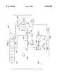
- FIG. 1 is an example of a schematic system diagram for a combined cycle plant according to the present invention.
- FIG. 1 An embodiment of the present invention will be explained with FIG. 1.
- Reference Number 100 is a gas turbine plant. This plant is mainly composed of a gas turbine 101, an air compressor 102 which is operated by the gas turbine 101, and a combustion chamber 103 for combusting fuel with compressed air which is formed by the air compressor 102.
- Reference Number 200 is an exhaust heat recovery boiler. This boiler uses exhaust gas of the gas turbine 101 as a heat source, and is mainly composed of a high pressure steam generator 201, an intermediate pressure steam generator 202, and a low pressure steam generator 203.
- Reference Number 300 is a steam turbine plant. This plant is mainly composed of a high pressure turbine 301 which receives high pressure steam from the exhaust heat recovery boiler 200, an intermediate pressure turbine 302 which receives steam from the aftermentioned recovery line 405 or the like, and a low pressure turbine 303 which receives low pressure steam from the exhaust heat recovery boiler 200.
- Reference Number 400 is a steam cooling system.
- This system is mainly composed of a cooling steam supply line 401 which is connected to the exhaust part 304 of the high pressure turbine 301, a first steam cooling line 402 which branches from the cooling steam supply line 401 and cools the combustion chamber 103, and second and third steam cooling lines 403, 404 which branch from the cooling steam supply line 401, similarly to the first steam cooling line 402, and cooling the high temperature parts which are cooled of the gas turbine 101.
- Reference Number 800 is a warming steam exhaust line. This line is composed of a duct 801 which connects a recovery line 405 and a gas turbine exhaust duct 802.
- an auxiliary steam source 807 supplies auxiliary steam for warming to the steam cooling system 400 via duct 803, and the steam used for warming of the cooling system 400 is exhausted from the gas turbine exhaust duct 802 via duct 801.
- the gas turbine exhaust duct 802 is designed to have a high silencing capacity. Therefore, noise which is produced by the steam used for warming and exhausted from the duct 801 is fully silenced by the gas turbine exhaust duct 802.
- the opening and shutting of the regulator valves 804, 805, 806 which are installed in the steam cooling system 401, recovery line 405, and the duct 405 are controlled by the controller (not shown), and the exhaust line 800 is formed by the regulation of these regulator valves 804, 805, 806.
- the noise which is produced by the steam used for warming is effectively silenced by gas turbine exhaust duct 802 which was originally part of the plant. Therefore, the noise can be silenced without additional equipment such as a silencer or an exhaust pipe for the warming steam, or additional costs for the additional equipment.
Landscapes
- Engineering & Computer Science (AREA)
- Chemical & Material Sciences (AREA)
- Combustion & Propulsion (AREA)
- Mechanical Engineering (AREA)
- General Engineering & Computer Science (AREA)
- Engine Equipment That Uses Special Cycles (AREA)
Abstract
Description
Claims (1)
Applications Claiming Priority (2)
| Application Number | Priority Date | Filing Date | Title |
|---|---|---|---|
| JP19460496A JP3825092B2 (en) | 1996-07-24 | 1996-07-24 | Combined cycle power plant |
| PCT/JP1998/000263 WO1999037902A1 (en) | 1996-07-24 | 1998-01-23 | Combined cycle electric power plant |
Publications (1)
| Publication Number | Publication Date |
|---|---|
| US6164056A true US6164056A (en) | 2000-12-26 |
Family
ID=16327318
Family Applications (1)
| Application Number | Title | Priority Date | Filing Date |
|---|---|---|---|
| US09/381,612 Expired - Lifetime US6164056A (en) | 1996-07-24 | 1998-01-23 | Combined cycle electric power plant |
Country Status (1)
| Country | Link |
|---|---|
| US (1) | US6164056A (en) |
Cited By (1)
| Publication number | Priority date | Publication date | Assignee | Title |
|---|---|---|---|---|
| US20090260342A1 (en) * | 2006-09-27 | 2009-10-22 | Mitsubishi Heavy Industries, Ltd. | Gas turbine |
Citations (7)
| Publication number | Priority date | Publication date | Assignee | Title |
|---|---|---|---|---|
| US4424668A (en) * | 1981-04-03 | 1984-01-10 | Bbc Brown, Boveri & Company Limited | Combined gas turbine and steam turbine power station |
| JPH05163960A (en) * | 1991-12-16 | 1993-06-29 | Tohoku Electric Power Co Inc | Combined cycle power generation plant |
| JPH0693879A (en) * | 1992-09-11 | 1994-04-05 | Hitachi Ltd | Combined plant and its operating method |
| JPH08148035A (en) * | 1994-11-24 | 1996-06-07 | Hitachi Chem Co Ltd | Conductive material and conductive paste using this conductive material |
| US5613356A (en) * | 1994-03-21 | 1997-03-25 | Abb Management Ag | Method of cooling thermally loaded components of a gas turbine group |
| JPH09112215A (en) * | 1995-10-16 | 1997-04-28 | Toshiba Corp | Gas turbine plant and operating method thereof |
| US5979156A (en) * | 1996-10-29 | 1999-11-09 | Mitsubishi Heavy Industries, Ltd. | Cooling steam system for steam cooled gas turbine |
-
1998
- 1998-01-23 US US09/381,612 patent/US6164056A/en not_active Expired - Lifetime
Patent Citations (7)
| Publication number | Priority date | Publication date | Assignee | Title |
|---|---|---|---|---|
| US4424668A (en) * | 1981-04-03 | 1984-01-10 | Bbc Brown, Boveri & Company Limited | Combined gas turbine and steam turbine power station |
| JPH05163960A (en) * | 1991-12-16 | 1993-06-29 | Tohoku Electric Power Co Inc | Combined cycle power generation plant |
| JPH0693879A (en) * | 1992-09-11 | 1994-04-05 | Hitachi Ltd | Combined plant and its operating method |
| US5613356A (en) * | 1994-03-21 | 1997-03-25 | Abb Management Ag | Method of cooling thermally loaded components of a gas turbine group |
| JPH08148035A (en) * | 1994-11-24 | 1996-06-07 | Hitachi Chem Co Ltd | Conductive material and conductive paste using this conductive material |
| JPH09112215A (en) * | 1995-10-16 | 1997-04-28 | Toshiba Corp | Gas turbine plant and operating method thereof |
| US5979156A (en) * | 1996-10-29 | 1999-11-09 | Mitsubishi Heavy Industries, Ltd. | Cooling steam system for steam cooled gas turbine |
Cited By (1)
| Publication number | Priority date | Publication date | Assignee | Title |
|---|---|---|---|---|
| US20090260342A1 (en) * | 2006-09-27 | 2009-10-22 | Mitsubishi Heavy Industries, Ltd. | Gas turbine |
Similar Documents
| Publication | Publication Date | Title |
|---|---|---|
| US6615585B2 (en) | Intake-air cooling type gas turbine power equipment and combined power plant using same | |
| US6481212B2 (en) | Combustion turbine cooling media supply system and related method | |
| US5471832A (en) | Combined cycle power plant | |
| KR100268611B1 (en) | Combined cycle power plant and supplying method of coolant therof | |
| EP0939202B1 (en) | Steam cooled gas turbine system | |
| JP3340505B2 (en) | Gas Turbo Group Operation | |
| US20050034445A1 (en) | Method and apparatus for combined cycle power plant operation | |
| US6244039B1 (en) | Combined cycle plant having a heat exchanger for compressed air | |
| JPH10115229A (en) | Gas turbine and operating method thereof | |
| US20110016870A1 (en) | Method and apparatus for improved gas turbine efficiency and augmented power output | |
| JPH0658167A (en) | Gas turbine device | |
| US6286297B1 (en) | Steam cooled type combined cycle power generation plant and operation method thereof | |
| JP2000130108A (en) | How to start a combined cycle power plant | |
| US6164056A (en) | Combined cycle electric power plant | |
| JP4208397B2 (en) | Start-up control device for combined cycle power plant | |
| US5251434A (en) | Pressurized fluidized-bed boiler power plant | |
| CA2284493C (en) | Combined cycle electric power generating plant | |
| EP0974737A1 (en) | Combined cycle power plant | |
| US6311474B2 (en) | Combined cycle electric power plant | |
| CA2284491C (en) | Combined cycle electric power plant | |
| JP3446185B2 (en) | Operating method of steam-cooled gas turbine | |
| JPH08218894A (en) | Intercooler for fuel gas compressor | |
| JP3276276B2 (en) | Gas turbine cooling system | |
| JP3825092B2 (en) | Combined cycle power plant | |
| JP4473464B2 (en) | Operation method of combined cycle power plant |
Legal Events
| Date | Code | Title | Description |
|---|---|---|---|
| AS | Assignment |
Owner name: MITSUBISHI HEAVY INDUSTRIES, LTD., JAPAN Free format text: ASSIGNMENT OF ASSIGNORS INTEREST;ASSIGNORS:YAMAMOTO, HIROYUKI;YASURAOKA, JUN;REEL/FRAME:011207/0931 Effective date: 19990914 |
|
| STCF | Information on status: patent grant |
Free format text: PATENTED CASE |
|
| FEPP | Fee payment procedure |
Free format text: PAYOR NUMBER ASSIGNED (ORIGINAL EVENT CODE: ASPN); ENTITY STATUS OF PATENT OWNER: LARGE ENTITY |
|
| FPAY | Fee payment |
Year of fee payment: 4 |
|
| FPAY | Fee payment |
Year of fee payment: 8 |
|
| FEPP | Fee payment procedure |
Free format text: PAYER NUMBER DE-ASSIGNED (ORIGINAL EVENT CODE: RMPN); ENTITY STATUS OF PATENT OWNER: LARGE ENTITY Free format text: PAYOR NUMBER ASSIGNED (ORIGINAL EVENT CODE: ASPN); ENTITY STATUS OF PATENT OWNER: LARGE ENTITY |
|
| FPAY | Fee payment |
Year of fee payment: 12 |
|
| AS | Assignment |
Owner name: MITSUBISHI HITACHI POWER SYSTEMS, LTD., JAPAN Free format text: ASSIGNMENT OF ASSIGNORS INTEREST;ASSIGNOR:MITSUBISHI HEAVY INDUSTRIES, LTD.;REEL/FRAME:035101/0029 Effective date: 20140201 |