US6148584A - Trim attachment system - Google Patents
Trim attachment system Download PDFInfo
- Publication number
- US6148584A US6148584A US09/117,671 US11767198A US6148584A US 6148584 A US6148584 A US 6148584A US 11767198 A US11767198 A US 11767198A US 6148584 A US6148584 A US 6148584A
- Authority
- US
- United States
- Prior art keywords
- spline
- trim
- wall
- strip
- assembly
- Prior art date
- Legal status (The legal status is an assumption and is not a legal conclusion. Google has not performed a legal analysis and makes no representation as to the accuracy of the status listed.)
- Expired - Fee Related
Links
Images
Classifications
-
- E—FIXED CONSTRUCTIONS
- E06—DOORS, WINDOWS, SHUTTERS, OR ROLLER BLINDS IN GENERAL; LADDERS
- E06B—FIXED OR MOVABLE CLOSURES FOR OPENINGS IN BUILDINGS, VEHICLES, FENCES OR LIKE ENCLOSURES IN GENERAL, e.g. DOORS, WINDOWS, BLINDS, GATES
- E06B1/00—Border constructions of openings in walls, floors, or ceilings; Frames to be rigidly mounted in such openings
- E06B1/04—Frames for doors, windows, or the like to be fixed in openings
- E06B1/06—Wooden frames
- E06B1/08—Wooden frames composed of several parts with respect to the cross-section of the frame itself
-
- E—FIXED CONSTRUCTIONS
- E04—BUILDING
- E04F—FINISHING WORK ON BUILDINGS, e.g. STAIRS, FLOORS
- E04F19/00—Other details of constructional parts for finishing work on buildings
- E04F19/02—Borders; Finishing strips, e.g. beadings; Light coves
- E04F19/04—Borders; Finishing strips, e.g. beadings; Light coves for use between floor or ceiling and wall, e.g. skirtings
- E04F19/0459—Borders; Finishing strips, e.g. beadings; Light coves for use between floor or ceiling and wall, e.g. skirtings characterised by the fixing method
- E04F19/0463—Plinths fixed by snap-action in a direction perpendicular to the wall
-
- E—FIXED CONSTRUCTIONS
- E04—BUILDING
- E04F—FINISHING WORK ON BUILDINGS, e.g. STAIRS, FLOORS
- E04F19/00—Other details of constructional parts for finishing work on buildings
- E04F19/02—Borders; Finishing strips, e.g. beadings; Light coves
- E04F19/04—Borders; Finishing strips, e.g. beadings; Light coves for use between floor or ceiling and wall, e.g. skirtings
- E04F19/0495—Plinths fixed around wall openings or around corners of walls
-
- E—FIXED CONSTRUCTIONS
- E06—DOORS, WINDOWS, SHUTTERS, OR ROLLER BLINDS IN GENERAL; LADDERS
- E06B—FIXED OR MOVABLE CLOSURES FOR OPENINGS IN BUILDINGS, VEHICLES, FENCES OR LIKE ENCLOSURES IN GENERAL, e.g. DOORS, WINDOWS, BLINDS, GATES
- E06B1/00—Border constructions of openings in walls, floors, or ceilings; Frames to be rigidly mounted in such openings
- E06B1/62—Tightening or covering joints between the border of openings and the frame or between contiguous frames
- E06B2001/622—Tightening or covering joints between the border of openings and the frame or between contiguous frames especially adapted for door frames; Joint covering devices where the wall surface is parallel to the adjacent door or window frame part
Definitions
- This invention relates to wood trim, of the kind used to trim the edges of door frames and window frames, wainscotting, and also baseboards and skirting boards, crown mouldings, etc, in houses and other buildings.
- the invention is a development of the technology disclosed in PCT/GB-93/00583, published Sep. 30, 1993 as WO-93/19273.
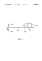
- FIG. 1 is a cross-section of a spline-strip, for use in the invention
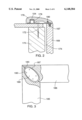
- FIG. 2 shows the strip of FIG. 1 in an installation
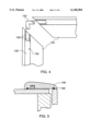
- FIG. 3 shows a mitered corner between two lengths of trim
- FIG. 4 shows a mitred corner between two spline strips
- FIG. 5 shows trim to which draft-excluding seals have been added
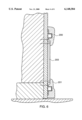
- FIG. 6 is a cross-section of a baseboard installation
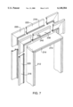
- FIG. 7 is a pictorial view of a kit of components for a trim system
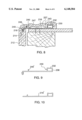
- FIG. 8 is a cross-section of another spline-strip
- FIG. 9 is a cross-section of another spline-strip
- FIG. 10 is a cross-section of another spline-strip
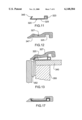
- FIG. 11 is a cross section of another trim attachment strip.
- FIG. 12 is a cross section of another trim strip for engagement with the trim attachment strip of FIG. 11.
- FIG. 13 is a cross section of the trim strip and spline strip of FIGS. 11 and 12 attached to a wall and frame assembly.
- FIG. 14 is a cross section of the trim strip and spline strip of FIGS. 11 and 12 attached to a wall and frame assembly with fasteners in place.
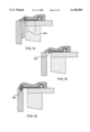
- FIG. 15 is a cross section of another form of trim strip and spline strip attached to a wall and frame assembly.
- FIG. 16 is a cross section of another form of trim strip and spline strip attached to a wall and frame assembly.
- FIG. 17 is a cross section of another form of trim strip and trim attachment strip.
- FIG. 1 shows a trim attachment strip 150, which is formed as a plastic extrusion.
- FIG. 2 shows the strip of FIG. 1 in use to attach a piece of wood trim to a wall, associated with a door opening.
- the profile of the strip 150 includes a base or web 152, which lies flat against the wall. (The web may be bowed slightly, in profile, so that when the strip is nailed flat to the wall the edges of the profile are pressed against the wall.) Protruding outwards from the web 152 is a spline 154.
- the spline 154 has the form of a hollow rectangular box, comprising left and right side walls 156 and a roof 158.
- the roof 158 is slightly dished or curved, as shown.
- the profile includes a small, radiused promontory 160.
- the spline 154 is slightly thicker at its outer end, or roof end.
- Protruding inwards (with respect to the wall) from the back of the spline-strip 150 is a protrusion or bar 163. This protrusion is ridged, as shown in FIG. 1.
- the rib 165 protrudes not at right angles, but at the slight angular inclination as shown in FIG. 1.
- FIG. 2 shows the spline-strip 150 installed.
- the ridged protrusion 163 engages a groove 167 cut in and along the length of the edge of the (wood) door-jamb-piece 169. By this engagement, the spline-strip 150 and the jamb-piece 169 are locked together against relative lateral movement.
- the door-jamb-piece 169 is secured in place relative to the door opening by virtue of the fact that the spline-strip 150 is secured to the wall stud 170 by means of screws 172. (Nails, staples, etc, may be used to secure the spline-strip.)
- the exact position and orientation of the jamb-piece 169 in the opening can be adjusted by adjusting the exact place in which the spline-strip is fixed to the stud.
- the jamb-piece as illustrated in FIG. 2 is located at the door-hinge-side of the opening, and it will be understood that the corresponding jamb-piece at the door-open-side of the opening is secured in a similar manner. Also, the jamb-piece of the lintel of the opening is secured in similar manner.
- the spline-strip 150 arranged and used as described, provides for a very simple installation of the door-jamb-pieces and the lengths of trim around the door, even though the installer may not be a skilled craftsman.
- the arrangement as described enables the installation to be done in a manner that make it easy to ensure that the mitred corners of the finishing wood trim will be exactly square and even.
- a door opening is not exactly square and even.
- the installer may temporarily secure the lintel jamb-piece and spline-strip, and then, with the aid of a set square or jig, align the hinge-side and the open side-jamb pieces and spline-strips. He may install both the inside-the-room and the outside-the-room strips at the same time. Generally, the installer will find that he can easily set the lintel piece first, and then can set the two side pieces exactly at right angles to the lintel piece.
- FIG. 2 it will be noted that no shims are required between jamb-piece and stud in order to hold the jamb-pieces in their correct location in the opening.
- the jamb-pieces are fully located and constrained by the spline-strips, and by the screws 172.
- the space 174 is made large enough to accommodate such out of squareness and other unevenness as may be required, to ensure that the jamb-pieces and the spline-strips can be put in place exactly at right angles to each other.
- the jamb-pieces 169, spline-strips 150, and the lengths of trim 176 may be pre-made in-factory.
- the purchaser states the size of the door, and is supplied with the appropriately-sized kit; all the items in the kit are pre-cut to size and all mitres are pre-cut on accurate factory machinery.
- a kit may be made up of pre-cut and pre-mitred spline-strips; also, pre-cut and pre-mitred lengths of trim (which are not only pre-cut and pre-mitred, but are also fully and finally finished); and also, fully and finally finished jamb-pieces. Since doors come in a limited number of standard sizes, it is economical for wood trim shops to hold stocks of the pre-cut trim, spline-strip, and jamb-pieces in kits for the various standard sizes of door.
- the pre-made trim kits provide even the amateur carpenter with a simple way of ensuring that all mitres are not only cut perfectly, but are installed at an accurate right angle. This is in addition to the other benefits of the system: (a) the fact that no nails etc are used to secure the trim means that the trim may be made with a factory-applied finish; and (b) the trim is removable and can be removed and replaced to simplify the task of wall-papering, painting, etc.
- the installer might wish to remove a sliver of material from the edge of a jamb-piece 169, for example to make the edge lie flush with the wall surface.
- the grooves 167 should be made deep enough to allow for some material to be removed from the jamb-piece, and still leave the groove deep enough that the ridged protrusion 163 does not bottom in the groove.
- the profile of the wood trim 176 may be provided with a space to receive electrical wires running inside the trim. Such wires may be held in place with special clips, which hook into holes drilled in the web of the spline-strip. Alternatively, wires can be secured simply by passing a staple around the wire and through the web.
- the trim 176 is provided with a spline-groove 178 and a rib-groove 180.
- the length of trim is first assembled over the leaning rib 165; the rib 165 bends slightly when the trim is pressed down over the spline 154, resulting in a (slightly) heavier contact force between the rib 165 and the trim 176, and a force which tends to draw the edge of the trim into a slightly tighter contact with the jamb-piece.
- the spline-groove 178 and the spline 154 have a slight interference fit, especially over the roof-end of the spline, where, as mentioned, the spline is slightly thicker because of the corner promontories 160.
- the roof 158 is able to bend (in a buckling mode), to the extent required for the spline 154 to fit in the groove 178 with a good contact force.
- the hollow-box form of the spline 154 profile is excellent in providing just the right balance between stiffness and resilience in the spline.
- the solid-spline system as described in earlier publications is able to provide excellent retaining and holding power of the trim to the spline, even though the spline has only a light interference, hardly any interference, or no interference at all, with the spline-groove.
- the coefficient of friction between the PVC of the spline and the wood of the spline-groove can be low enough that the designer wishes to resort to interference to provide the holding power needed.
- the roof 158 serves to hold the outer ends of the left and right walls 156 apart.
- the roof 158 is resilient enough, in the bending/buckling mode, to allow the walls to bend inwards slightly, if the groove should be cut narrow, and yet enough interference is provided to ensure good holding power if the groove should be cut on the wide end of its permitted tolerance range. This just-right degree or rate of resilience of the spline is enhanced if the roof 158 is given the nominal curvature, as shown.
- the thickness of the roof can be adjusted, also, to provide just the right degree of resilience: it has been found that making the roof slightly thinner than the walls can help give the right balance between a too-hard spline, which has no "give” and splits the wood trim if the groove is slightly too tight, and a too-soft spline, in which the spline does not provide enough grip to the sides of the groove.
- the hollow-box design of spline enables the spline to grip the trim tightly enough for good securement, over a tolerated range of groove widths.
- the degree of resilience attributable to the hollow-box profile of the (plastic) spline may be expected to provide holding power over a tolerance range of the order of 0.02 mm.
- the hollow-box profile allows a greater dimensional magnitude of interference between spline and spline-groove than was the case with the solid spline.
- a solid plastic spline has hardly enough resilience to permit any interference; on the other hand, two cantilevered arms would have too much resilience.
- two cantilevered arms joined by a roof (which is what the hollow-box profile amounts to) has just the right degree of resilience to provide a good holding force without demanding difficult-to-manufacture tolerances.
- Interference-fits generally require tight tolerances: the hollow-box profile for the plastic spline eases that requirement enough that a factory-cut groove in a length of solid oak or other wood trim can be accurate enough.
- a problem that can sometimes arise with mitred corners is that the wall is not quite flat in the plane of the wall. As a result, at a mitred corner, the horizontal lintel trim might protrude perhaps a half-millimeter further out from the wall than the vertical trim. Even though the mitre might be exactly a right angle, such protrusion-mismatch can be quite noticeable.
- FIG. 3 shows how the lengths of trim may be joined together at the mitred corners, in a way that eliminates protrusion-mismatch.
- the mitred edge 183 of the vertical length of trim 185, and the corresponding mitred edge of the horizontal length of trim 186, are provided with slots 187, into which is inserted a biscuit 189.
- the biscuit 189 conventionally, is a piece of hardwood or plastic sheet formed to the oval shape as shown.
- the biscuits may be glued in place, or, if the trim profile is of appropriate thickness, the biscuits may be screwed in place, as at 190. Of course, the screws are screwed in from the back of the trim, and must be short enough not to extend right through the trim.
- the trim lengths 185,186 are secured together before being placed on the wall. This means that the installer must be able to rely on the accuracy of the mitres, as cut, in both the trim lengths and the spline-strips. It will be understood that securing the trim-lengths together with biscuits, and then placing the secured-together trim-lengths on the spline-strips, poses a very demanding requirement for accuracy of the mitres and of the dimensions of the pieces. However, such accuracy is available if the mitred joints between the trim lengths and the spline strips are factory-made to suit the particular door size. The pre-grooved door-jamb-pieces 169 should be included also in the same kit.
- Pre-making the sub-assembly of the trim-lengths by pre-gluing biscuit connectors into the joints is much more efficacious in the case of window trim.
- window trim there are four lengths of trim, in the form of an enclosed rectangle.
- a window trim sub-assembly, being an enclosed rectangle, is much more robust than a door trim sub-assembly, and can be expected to survive handling by amateur craftsmen.
- the two spline-strips making up the joint also may be expected to have the mismatch. Indeed, in some cases, if the mismatch of the spline-strips is eliminated, there will be no need to cater for mismatch in the trim itself. Certainly, the installation and attachment of the trim lengths (and the possible detachment of the trim-lengths at some future time) is much more convenient if the trim-lengths are not permanently glued together as a pre-made sub-assembly.
- the corner-pieces 192 may serve in this way equally for door trim as for window trim.
- More than one spline or rib may be provided on the strip, having also a hollow interior, and corresponding corner pieces may be provided for that also.
- a preferred way of installing the trim and its mounting system may be described as follows.
- the lengths of trim, the spline-strips, and the door-jamb-pieces are all, pre-mitred, and pre-finished, in-factory, and are purchased by the installer as a kit for a particular width of door, or door opening.
- the kit is opened in the room, and the door-jamb-pieces are assembled, on edge, on the floor.
- the spline-strips for the inside of the room are assembled to the door-jamb pieces; the ribbed protrusions 163 are entered into the groove 167 while the jamb-pieces are still laid on the floor.
- the door-jamb pieces may now be secured together at the mitred corners, using appropriate fasteners. (Of course, these fasteners should be so arranged as not to be visible after installation.)
- the assembly comprising the fixed-at-the-corners jamb-pieces and the inside-the-room spline-strips, which are already assembled to the jamb-pieces, may now be lifted off the floor of the room, and the assembly placed in the door opening.
- the installer will generally be able to tell, by eye, by looking at the mitred comers, both of the jamb-pieces and of the spline-strips, whether the corners are accurately at right angles. It may be regarded that if the installer cannot see any out-of-squareness at the corner by looking at the line of the mitre, then the out-of-squareness is so small it can be ignored. Set squares and other instruments are generally not required. The installer must be able to "trust" the mitres for squareness, but this is acceptable with factory-made mitres.
- the spline-strips are secured to the wall when the installer is satisfied, looking at the lines of the mitres, that the corners are square.
- the door jamb-pieces are secured by securing the spline-strips to the wall.
- the outside-the-room spline-strips may be installed, using the grooves 167 cut in the far edges of the jamb-pieces.
- the outside-the-room spline strips are secured to the wall also.
- the spline-strips and the wood trim When installing the spline-strips and the wood trim in a case of renovation, rather than original installation, it will generally be impractical for the jamb-pieces to be provided with grooves 167. For renovation work, therefore, the spline-strip is provided without the protrusion 163. Also, for window trim, the protrusions 163 will not be present.
- FIG. 5 shows a useful variation to the trim, in which further grooves 196 are provided in the cut-profile of the trim. Rubber sealing strips 198 are carried in the grooves 196, and serve to prevent drafts which may be emanating from inside the (hollow) wall and from the space 174, from leaking around the trim.
- FIG. 6 shows another manner in which the invention may be applied: for wide trim, such as may be required for a baseboard, the trim may be provided in, for example, three sections.
- the outer two sections 200,201 are attached by means of the spline attachment system of the invention, whereas the middle section 203 is screwed in place. Normally, the screws holding the middle section remain concealed by the outer two sections.
- the outer two sections being spline-held, can be removed.
- a similar arrangement may be employed also for crown moulding trim.
- FIG. 7 shows a kit of components, as may be used for securing trim around a door, when the application is of such a kind that the door jamb can be made specially to suit the trim system. It can be arranged, in that case, in particular, that the door jamb pieces 210,212 may be provided with slots or grooves 214 along their edges (similar to FIG. 2).
- the spline-strips 216 are provided with integral barbed or ridged bars 218, which engage the groove.
- the spline-strips 216 are present on both sides of the door, such a fixing system is extraordinarily strong, even though the bars 218 are simply pressed into the grooves 214.
- the door jamb pieces 210,212 need not in fact be screwed to the door frame at all, themselves, but can be held in place entirely by means of the spline-strips 216.
- the spline strips of course are nailed or stapled, through the plasterboard, to the door frame in the wall.
- the carpenter may attach the door hinges, latch, etc, to the jamb pieces with full confidence that even if the door were to be slammed hard the jamb is rigidly secured.
- the jamb-pieces may be pre-finished, in-factory, since no through-fasteners (which might damage the finish) are required to hold them in place.
- the width of the wall is not quite the same as the width of the jamb-piece 210,212, or the wall may be slightly bowed. Mis-match due to thickness variations or lack of straightness can easily be accommodated (within limits, of course) by the spline-strips 216, which are fairly flexible in the plane of the wall, and yet still the jamb-pieces are held very firmly in place relative to the wall, by virtue of the securement of the spline strips to the wall.
- the bars 218, being barbed, remain firmly secured to the jamb-pieces, once assembled therein.
- the force on the groove 214 is considerable, but the jamb-piece (much more so than the trim) is thick and chunky, and is not prone to cracking due to the heavy forces.
- the wood trim can be removed from the spline-strips by hand manipulation, the barbed bars 218 are a barely-removable fit in the grooves 214.
- the kit of components of FIG. 7 includes corner pieces 220 of the spline-strip. To form these corner pieces, two pieces of the plastic spline-strip extrusion are cut off at (exactly) 45 degrees. The two pieces are welded together at (again exactly) 45 degrees. These manufacturing processes can be carried out in-factory, where the required degree of accuracy is easy to obtain.
- the corner-pieces 220 are pressed into the horizontal and vertical jamb-pieces 210,212. This is done on both sides of the wall, ie inside and outside the room. (The wood trim is absent at this time.)
- the corner-pieces are attached to the wall, by screwing, stapling. etc. With the corner-pieces of the spline-strip secured to the jamb-pieces, it is ensured that the intersections of the jamb-pieces are accurately at right angles, simply by fixing the corner-pieces of the spline-strip to the wall while the corner-pieces are assembled to the jamb-pieces. Both the inside and outside corner-pieces are secured at this time.
- the horizontal and vertical fill-in pieces 223,225 of the spline-strip are cut to length, their barbed bars 218 pressed into the grooves 214 in the jamb-pieces,
- the fill-in pieces are fixed to the wall, again both inside and out. No particular care and skill is needed to align the fill-in pieces of spline-strip with the jamb-pieces.
- Each is constrained by the other to adopt the correct position, without the need for measurements, or marking out, etc, by the carpenter.
- jamb-pieces 210,212 are secured to the spline-strips 216 over their whole lengths, which is why the securement of the jamb-pieces is so firm and rigid. In other installations, when door shims are used for example, jamb-pieces are secured at only perhaps two or three points along their lengths.
- the trim 227 (FIG. 8) is pounded on.
- the horizontal piece of trim is pre-cut, in the factory, to match the nominal door size; that is to say, to match exactly the width of the horizontal jamb-piece 210.
- the vertical pieces of trim may be arranged to be cut to the correct height by the carpenter, the mitred corners of the vertical of trim being done in the factory.
- the fixing of the spline-strip 216 is done by inserting screws into the spline 230 itself--the spline being hollow, the screws go through clearance holes in the roof 232 of the spline, and abut the floor 234 of the spline. Staples (or screws, or nails, or other suitable fasteners) may be inserted through the main flat area 236 of the spline-strip, into the wall.
- the use of the pre-made corner-pieces 220 makes it substantially less demanding to arrange that the piece of trim, when assembled, fit exactly together.
- the arms of the corner 220 are long enough to ensure the pieces of trim are forced to be correctly aligned to the corner-pieces.
- the spline 230 itself has the bowed and slightly thinned roof 232, as previously described.
- the side walls 238 of the hollow spline are plain, and may be straight (parallel) or may have a slight draft angle.
- the rib 240 is curved.
- the curved rib 240 interacts with the profile 243 of the trim piece in such a way that the rib presses forcefully against the side 245 of a groove 247 cut in the trim.
- the friction arising from this forceful contact holds the inner end 249 of the trim tight against the wall. (If only the main spline 230 were provided, i.e. if the rib 240 were not present, the inner end 249 of the trim might tend to lift.)
- the grooves in the jamb-pieces can be readily provided in new installations, it is, in general, not possible to provide grooves in the jamb pieces if the jamb pieces are already in existence in the building.
- the carpenter cuts the horizontal trim-piece with mitred ends, suitably to fit the door size. (Or, lumber stores may stock already-mitred-both-ends pieces of trim to suit standard door widths.)
- the carpenter assembles the two corner pieces to the horizontal trim piece, and presents those components in place on the wall, and marks the wall. He removes the corner pieces from the trim, and then nails the corner-pieces to the wall, in the positions as marked.
- a horizontal fill-in piece of spline-strip may be out slightly shorter than the space left between the corners-pieces, and this fill-in piece now in turn is pressed into the horizontal trim; the trim is then assembled lightly to the already fixed corner, and marks are made on the wall for the line of the fill-in piece. The trim is removed, and the fill-in piece nailed to the marks on the wall.
- the carpenter can place the vertical piece of spline-strip similarly accurately. With all the spline strips all in place, finally the trim can be pounded on.
- the rib 240' is arranged to face the other way, i.e. to touch the other side of the groove of the trim. Now, the pressure between the rib 240' and the side of the groove 247 drives the profile of the plastic spline-strip into tension and the profile of the wood trim into compression, an arrangement that may be preferred in some cases.
- trim fixing systems are particularly suitable when the trim is of solid wood of the kind used for decorative trims, e.g. oak. It is a demanding task to secure solid wood trim, because the wood has a tendency to split at the corners of grooves. Therefore, the splines cannot be too tight a fit in the grooves: as explained, it is only when the splines and the grooves engage each other over their whole lengths that a nominally loose fit is found to be tight enough to hold the trim in place.
- extruded plastic can change dimensions by as much as 2-3% with changes in humidity and temperature. Obviously, the householder does not want the trim to fall off in the winter, and by engineering the fit to obtain over the width of a relatively thin (e.g. 1 cm) spline, such percentage dimensional changes have insignificant effect on the fit. If the fit were between two surfaces that were, say, 5 cm apart, instead of 1 cm apart, the change of dimensions might easily lead to trim fall-off problems.
- FIGS. 11-17 show another manner of arranging the trim attachment system.
- FIGS. 11-17 show a way of drawing the inner lip of the trim tightly against the side edge surface of the door jamb.
- the extruded plastic spline-strip 320 has a profile that includes a hollow spline 323 (the spline being as previously described, and engaging with a complementary groove 325 in the wood trim 327).
- the extruded profile also includes a flat web 329, by which the spline-strip can be nailed, stapled, etc, through the plasterboard 340, into the door frame stud 342.
- the inner end of the extruded profile includes a tongue 345.
- the tongue is angled, either forwards as shown in FIG. 11, or backwards as shown in FIG. 17.
- the profile of the wood trim 327 (FIG. 12) includes a complementarily-angled slot 347.
- the slot 347 is simply cut with an angled saw-blade, which can be done on the same pass in which the overall profile of the wood trim was cut--that is to say, there is no need for the slot 347 to be cut by a separate operation, such as routing.
- the slot 347 is a little wider than the thickness of the tongue 345, i.e. the tongue is not tight in the slot.
- the intention is that the engagement between the angled tongue and the corresponding angled side of the slot gives rise to a force tending to draw the lip of the trim against the door jamb.
- FIG. 13 The manner of assembling the trim to the extrusion is shown in FIG. 13.
- the components are so dimensioned that the trim has to be pressed to the left in FIG. 13 in order for the trim to fit over the spline 323. Once the spline is engaged, this leftwards force on the lip-end of the trim is reacted against the spline, and thereby maintained.
- the leftwards force serves to drive the tongue 345 more deeply into the slot 347. Insofar as the tongue cannot move away from the wall, the lip of the trim is drawn towards the wall, and into contact with the door jamb.
- the force drawing the lip of the trim against the door jamb is reacted by the inherent resistance of the area of the extruded profile against moving away from the wall. If the extrusion were flimsy, the tongue might easily move away from the wall, and there would be little beneficial ability of the tongue and slot arrangement to draw the lip against the jamb. Therefore, the area of the extrusion that includes the tongue should be attached firmly to the wall, and also, that area should be of robust dimensions, so as to be capable of handling the forces acting on the tongue without undue deflection.
- FIG. 14 shows the assembled trim.
- the fasteners 349 holding the trim to the stud 350 should be reasonably close together, because the plastic is not firmly held against the wall in the spaces between the fasteners, and the profile of the plastic extrusion is not so rigid in the plane at right-angles to wall.
- the tongue 345 itself, having a considerable height in the direction at right-angles to the wall, lends rigidity for helping keep the extruded profile rigid in the along-the-jamb sense, i.e. in the intervals between the fasteners.
- the fasteners 349 should be as close to the tongue as can reasonably be done, as shown in FIG. 14.
- the trim-installation-contractor should be careful to cut the shims 352 off short.
- a slight protrusion of the shims could be accommodated by inserting more nails through the trim.
- the contractor has to be more careful now, because with the present trim, if the shims protrude even slightly proud over the surface, it can be expected that a gap will appear between the inner lip of the trim and the door jamb.
- a further enhancement to the extruded profile of the plastic strip can be provided, as shown.
- a springy arm 354 on which the tongue can be mounted.
- a suitable degree of resilience can be built into the springy arm 354, whereby the tongue is able to exert forces on the slot (i.e. forces drawing the lip of the trim into contact with the door jamb) over a wider tolerance range of undulations of the jamb. That is to say, the resilience of the arm 354 enables the FIG. 15 version to accommodate a greater range of undulations of the jamb.
- FIG. 16 shows another alternative version, which is similar to the system of FIG. 1, in that a barbed projection 356 firmly retains the inner edge of the extruded profile in a complementary groove in the jamb.
- the action of the tongue and the corresponding slot relies on the fact that the spline 323 is present.
- the spline enables a large force between the tongue and the slot to be applied, and to be reacted. It will be noted that the forces as described are generated without the wood being called upon to bend, nor even to snap into an indentation or over a promontory.
- FIG. 17 shows the tongue angled the other way. This is less preferred, in that when pieces are to be mitred at the corners, it is easier to assemble mitred pieces from the outside in, rather than from the inside out. Also, angling the tongue the other way puts the wood in tension, whereby the wood is inevitably more likely to crack than where the wood is put under compression.
Applications Claiming Priority (1)
| Application Number | Priority Date | Filing Date | Title |
|---|---|---|---|
| PCT/CA1996/000065 WO1997028342A1 (fr) | 1996-02-02 | 1996-02-02 | Systeme de fixation d'habillage |
Related Parent Applications (1)
| Application Number | Title | Priority Date | Filing Date |
|---|---|---|---|
| PCT/CA1996/000065 Continuation-In-Part WO1997028342A1 (fr) | 1996-02-02 | 1996-02-02 | Systeme de fixation d'habillage |
Publications (1)
| Publication Number | Publication Date |
|---|---|
| US6148584A true US6148584A (en) | 2000-11-21 |
Family
ID=4173137
Family Applications (1)
| Application Number | Title | Priority Date | Filing Date |
|---|---|---|---|
| US09/117,671 Expired - Fee Related US6148584A (en) | 1996-02-02 | 1998-07-31 | Trim attachment system |
Country Status (3)
| Country | Link |
|---|---|
| US (1) | US6148584A (fr) |
| AU (1) | AU4479396A (fr) |
| WO (1) | WO1997028342A1 (fr) |
Cited By (42)
| Publication number | Priority date | Publication date | Assignee | Title |
|---|---|---|---|---|
| US6343448B1 (en) * | 2000-02-28 | 2002-02-05 | Chun-Chen Lin | Auxiliary frame for improving conventional frame and method for working the same |
| US6474038B2 (en) | 2001-03-05 | 2002-11-05 | Nien Made Enterprise Co., Ltd. | Window shutter frame assembly and method for installation |
| US20030066257A1 (en) * | 2001-10-04 | 2003-04-10 | Barry Shovlin | Method for manufacturing a door and door manufactured therefrom |
| US6588159B1 (en) * | 2000-10-03 | 2003-07-08 | Richard D. Cotton, Jr. | Multipurpose door and window jamb assembly |
| US6745523B2 (en) * | 2000-12-26 | 2004-06-08 | Alpa Lumber Inc. | Fastening member for a window and door assembly |
| US20040123536A1 (en) * | 2002-12-27 | 2004-07-01 | Han-Sen Lee | Window frame molding system |
| US20040151540A1 (en) * | 2003-01-10 | 2004-08-05 | Clements Rodney J. | Door, window, crown and baseboard molding system with hidden fasteners and pre-formed corner receptacles and couplers |
| US20040188583A1 (en) * | 2002-10-09 | 2004-09-30 | Marsh Thomas R. | Cushioning device for furniture |
| US20040221540A1 (en) * | 2003-05-09 | 2004-11-11 | Simons Julia Edgerton | Decorative trim for architectural structures |
| GB2404931A (en) * | 2003-07-31 | 2005-02-16 | Ian Douglas Law | Locating and architectural component and method of installing in a building |
| US20060037260A1 (en) * | 2004-05-26 | 2006-02-23 | Prince Kendall W | Methods and systems of interior window framing |
| US20070095000A1 (en) * | 2005-10-17 | 2007-05-03 | Klise Manufacturing Company | Modular moulding with fitted spline joinery system |
| US20070125013A1 (en) * | 2005-11-14 | 2007-06-07 | Cuatro, Llc | Finishing system for wall openings |
| US20080010918A1 (en) * | 2006-07-14 | 2008-01-17 | Bruggink Bradley J | Nail fin for window frame assembly |
| GB2441217A (en) * | 2006-08-21 | 2008-02-27 | Bryan Alexander Wilson | Trim assembly |
| US20080066421A1 (en) * | 2006-09-19 | 2008-03-20 | Heppner Thomas J | Methods related to self-sealing structural installation strip assembly |
| US20080066400A1 (en) * | 2006-09-19 | 2008-03-20 | Heppner Thomas J | Self-sealing structural installation strip assembly |
| US20080092463A1 (en) * | 2006-10-19 | 2008-04-24 | Poirier Peter P | Glazing assembly for rough openings |
| US20080202049A1 (en) * | 2003-11-19 | 2008-08-28 | Adam Galas | Skirting Board |
| US20090044466A1 (en) * | 2007-08-13 | 2009-02-19 | Andres Craig E | Window and Door Frame Assembly Apparatus and Method |
| WO2009035502A1 (fr) * | 2007-09-11 | 2009-03-19 | Focal Point Products, Inc. | Système de modernisation pour portes, fenêtres et ouvertures à cadre |
| US20090100785A1 (en) * | 2007-09-26 | 2009-04-23 | Harvey Industries, Inc. | Interior window trim kit |
| US20090313921A1 (en) * | 2008-06-19 | 2009-12-24 | Tremco Incorporated | Modified glazing assembly for rough openings |
| US7815263B1 (en) | 2008-08-07 | 2010-10-19 | Wright Sandradee N | Candle box |
| US20100287869A1 (en) * | 2005-05-23 | 2010-11-18 | Oliver Stanchfield | Transition molding and installation methods therefor |
| US8484919B2 (en) | 2006-10-18 | 2013-07-16 | Pergo (Europe) Ab | Transitions having disparate surfaces |
| US8528285B2 (en) | 2009-03-27 | 2013-09-10 | Pergo (Europe) Ab | Joint cover assembly and kit comprising this joint cover assembly as well as installation method thereof |
| US8584426B2 (en) | 2010-06-04 | 2013-11-19 | Milgard Manufacturing Incorporated | Sash binder |
| US20140096472A1 (en) * | 2012-10-05 | 2014-04-10 | Fiber Cement Foam Systems Insulation, LLC | Method and A Device to Attach Building Trims |
| US20140174023A1 (en) * | 2011-01-13 | 2014-06-26 | Cory Halischuk | Apparatus for Trimming Interior Walls |
| US8793954B2 (en) | 2001-11-08 | 2014-08-05 | Pergo (Europe) Ab | Transition molding |
| US20150013256A1 (en) * | 2013-07-12 | 2015-01-15 | Joseph Mea | Themed modular ceiling and wall decor kit and system |
| US20150040510A1 (en) * | 2013-08-09 | 2015-02-12 | Certainteed Corporation | System, method and apparatus for trim for building products |
| US20150143771A1 (en) * | 2013-11-28 | 2015-05-28 | Sheldon Goodheart | Trim moulding system and method |
| US20150197979A1 (en) * | 2014-01-13 | 2015-07-16 | Ply Gem Industries, Inc. | System And Method For Installing Trim With A Hidden Fastener System |
| USD750809S1 (en) | 2014-07-28 | 2016-03-01 | Certainteed Corporation | Trim assembly |
| US20160326793A1 (en) * | 2015-05-05 | 2016-11-10 | Donald A. Michaud | Adjustable gasket assembly |
| US10017936B1 (en) * | 2010-11-24 | 2018-07-10 | Innovations & Ideas, Llc | Casing bead control joint |
| US10676941B1 (en) * | 2015-01-29 | 2020-06-09 | Jeremy P. Hoffman | Wall-attachment structure and system employing an intra-structural hinge for reinforcing preferred placement on a straight or curved wall |
| US10941606B1 (en) * | 2018-09-06 | 2021-03-09 | Endura Products, Llc | Connector system, apparatus and methods for a door frame assembly |
| SE544795C2 (sv) * | 2017-06-21 | 2022-11-15 | Nya Swedlist Ab | Salningssystem för lösgörbar fastsättning av salningsbräda och dörr/fönsterfoder genom clips och hullingar i spår i ett karmstycke samt i bräda och foder |
| WO2022261760A1 (fr) * | 2021-06-15 | 2022-12-22 | 2232904 Alberta Ltd. | Système de garniture modulaire |
Families Citing this family (5)
| Publication number | Priority date | Publication date | Assignee | Title |
|---|---|---|---|---|
| DE59804161D1 (de) * | 1998-05-08 | 2002-06-20 | Top Bautraeger M & R Baugmbh & | Vorrichtung zur verkleidung einer türzarge |
| GB2346404A (en) * | 1999-02-08 | 2000-08-09 | David Howarth | Applique architrave having a split lintel-piece for application to an existing opening, for example a window opening or doorway |
| EP1692353A4 (fr) * | 2003-11-28 | 2009-03-25 | James Hardie Int Finance Bv | Systeme de garniture d'avant-toit |
| CA2648966C (fr) | 2006-04-12 | 2015-01-06 | James Hardie International Finance B.V. | Element de construction renforce a surface etanche |
| EP2644818A1 (fr) * | 2012-03-16 | 2013-10-02 | Kurt Steineberg GmbH | Pièce de liaison |
Citations (5)
| Publication number | Priority date | Publication date | Assignee | Title |
|---|---|---|---|---|
| US3609928A (en) * | 1969-10-13 | 1971-10-05 | Anjac Plastics | Jamb structure |
| US4318951A (en) * | 1978-12-28 | 1982-03-09 | Hiromitsu Naka | Stair mat |
| US4730432A (en) * | 1986-05-20 | 1988-03-15 | Raumausstattung Willi Schafer | Molding track for carpeting |
| US5001877A (en) * | 1989-03-10 | 1991-03-26 | Edwards Troy C | Decorative wall and ceiling molding assembly |
| US5127204A (en) * | 1987-11-25 | 1992-07-07 | August Braun | Protective lath for making a plaster joint when plastering a wall |
Family Cites Families (8)
| Publication number | Priority date | Publication date | Assignee | Title |
|---|---|---|---|---|
| FR1376369A (fr) * | 1963-12-06 | 1964-10-23 | Plastopress Ag | Perfectionnements apportés aux plinthes composées de plusieurs éléments |
| DE2557057A1 (de) * | 1975-12-18 | 1977-06-30 | Bettermann Geb Schlagheck Ursu | Tuerverkleidung |
| US4642957A (en) * | 1984-12-11 | 1987-02-17 | Edwards Troy C | Interior wall trim system |
| DE3900907A1 (de) * | 1989-01-13 | 1990-07-26 | Hofstetter & Co Holzindustrie | Multifunkionsleiste |
| GB2239281A (en) * | 1989-12-19 | 1991-06-26 | Michael George Young | Door framing means and method |
| ES2086550T3 (es) * | 1990-07-20 | 1996-07-01 | Philip Ferdinando Villa | Panel ajustable y conjunto de montaje. |
| US5179811A (en) * | 1990-12-03 | 1993-01-19 | Walker William H | Decorative trimming system |
| US5348066A (en) * | 1992-03-23 | 1994-09-20 | Wilson Bryan A | Wood trim system |
-
1996
- 1996-02-02 WO PCT/CA1996/000065 patent/WO1997028342A1/fr active Application Filing
- 1996-02-02 AU AU44793/96A patent/AU4479396A/en not_active Abandoned
-
1998
- 1998-07-31 US US09/117,671 patent/US6148584A/en not_active Expired - Fee Related
Patent Citations (5)
| Publication number | Priority date | Publication date | Assignee | Title |
|---|---|---|---|---|
| US3609928A (en) * | 1969-10-13 | 1971-10-05 | Anjac Plastics | Jamb structure |
| US4318951A (en) * | 1978-12-28 | 1982-03-09 | Hiromitsu Naka | Stair mat |
| US4730432A (en) * | 1986-05-20 | 1988-03-15 | Raumausstattung Willi Schafer | Molding track for carpeting |
| US5127204A (en) * | 1987-11-25 | 1992-07-07 | August Braun | Protective lath for making a plaster joint when plastering a wall |
| US5001877A (en) * | 1989-03-10 | 1991-03-26 | Edwards Troy C | Decorative wall and ceiling molding assembly |
Cited By (75)
| Publication number | Priority date | Publication date | Assignee | Title |
|---|---|---|---|---|
| US6343448B1 (en) * | 2000-02-28 | 2002-02-05 | Chun-Chen Lin | Auxiliary frame for improving conventional frame and method for working the same |
| US6588159B1 (en) * | 2000-10-03 | 2003-07-08 | Richard D. Cotton, Jr. | Multipurpose door and window jamb assembly |
| US6745523B2 (en) * | 2000-12-26 | 2004-06-08 | Alpa Lumber Inc. | Fastening member for a window and door assembly |
| US6474038B2 (en) | 2001-03-05 | 2002-11-05 | Nien Made Enterprise Co., Ltd. | Window shutter frame assembly and method for installation |
| US20050223674A1 (en) * | 2001-10-04 | 2005-10-13 | Masonite Corporation | Method for manufacturing a door and door manufactured therefrom |
| US20030066257A1 (en) * | 2001-10-04 | 2003-04-10 | Barry Shovlin | Method for manufacturing a door and door manufactured therefrom |
| US8793954B2 (en) | 2001-11-08 | 2014-08-05 | Pergo (Europe) Ab | Transition molding |
| US7780206B2 (en) * | 2002-10-09 | 2010-08-24 | Tenn Tex Plastics, Inc. | Cushioning device for furniture |
| US20040188583A1 (en) * | 2002-10-09 | 2004-09-30 | Marsh Thomas R. | Cushioning device for furniture |
| US6807783B2 (en) * | 2002-12-27 | 2004-10-26 | Han-Sen Lee | Window frame molding system |
| US20040123536A1 (en) * | 2002-12-27 | 2004-07-01 | Han-Sen Lee | Window frame molding system |
| US20060120799A1 (en) * | 2003-01-10 | 2006-06-08 | Clements Rodney J | Door, window, crown and baseboard molding system with hidden fasteners and pre-formed corner receptacles and couplers |
| US20040151540A1 (en) * | 2003-01-10 | 2004-08-05 | Clements Rodney J. | Door, window, crown and baseboard molding system with hidden fasteners and pre-formed corner receptacles and couplers |
| US20040221540A1 (en) * | 2003-05-09 | 2004-11-11 | Simons Julia Edgerton | Decorative trim for architectural structures |
| GB2404931A (en) * | 2003-07-31 | 2005-02-16 | Ian Douglas Law | Locating and architectural component and method of installing in a building |
| US7870697B2 (en) * | 2003-11-19 | 2011-01-18 | Adam Galas | Skirting board |
| US20080202049A1 (en) * | 2003-11-19 | 2008-08-28 | Adam Galas | Skirting Board |
| US20140013682A1 (en) * | 2004-05-26 | 2014-01-16 | Kendall W. Prince | Methods and systems of interior window framing |
| US20120159882A1 (en) * | 2004-05-26 | 2012-06-28 | Prince Kendall W | Methods and systems of interior window framing |
| US8959852B2 (en) * | 2004-05-26 | 2015-02-24 | Outlook Window Products, L.L.C. | Methods and systems of interior window framing |
| US20060037260A1 (en) * | 2004-05-26 | 2006-02-23 | Prince Kendall W | Methods and systems of interior window framing |
| US8453397B2 (en) * | 2004-05-26 | 2013-06-04 | Kendall W. Prince | Methods and systems of interior window framing |
| US8024899B2 (en) * | 2004-05-26 | 2011-09-27 | Outlook Window Products, L.L.C. | Apparatus and systems of interior window framing |
| US8539731B2 (en) | 2005-05-23 | 2013-09-24 | Pergo (Europe) Ab | Transition molding and installation methods therefor |
| US8205410B2 (en) * | 2005-05-23 | 2012-06-26 | Pergo (Europe) Ab | Transition molding and installation methods therefor |
| US20100287869A1 (en) * | 2005-05-23 | 2010-11-18 | Oliver Stanchfield | Transition molding and installation methods therefor |
| US20070095000A1 (en) * | 2005-10-17 | 2007-05-03 | Klise Manufacturing Company | Modular moulding with fitted spline joinery system |
| US20070125013A1 (en) * | 2005-11-14 | 2007-06-07 | Cuatro, Llc | Finishing system for wall openings |
| US7392625B2 (en) * | 2006-07-14 | 2008-07-01 | Wisconsin Plastic Products, Inc. | Nail fin for window frame assembly |
| US20080010918A1 (en) * | 2006-07-14 | 2008-01-17 | Bruggink Bradley J | Nail fin for window frame assembly |
| US20090013636A1 (en) * | 2006-08-21 | 2009-01-15 | Bryan Alexander Wilson | Wood trim system |
| GB2441217A (en) * | 2006-08-21 | 2008-02-27 | Bryan Alexander Wilson | Trim assembly |
| US20080066421A1 (en) * | 2006-09-19 | 2008-03-20 | Heppner Thomas J | Methods related to self-sealing structural installation strip assembly |
| US20080066400A1 (en) * | 2006-09-19 | 2008-03-20 | Heppner Thomas J | Self-sealing structural installation strip assembly |
| US8484919B2 (en) | 2006-10-18 | 2013-07-16 | Pergo (Europe) Ab | Transitions having disparate surfaces |
| US8096088B2 (en) * | 2006-10-19 | 2012-01-17 | Tremco Incorporated | Glazing assembly for rough openings |
| US20080092463A1 (en) * | 2006-10-19 | 2008-04-24 | Poirier Peter P | Glazing assembly for rough openings |
| US8534011B2 (en) | 2007-08-13 | 2013-09-17 | Craig E. Andres | Window and door frame assembly apparatus and method |
| US8104241B2 (en) * | 2007-08-13 | 2012-01-31 | Andres Craig E | Window and door frame assembly apparatus and method |
| US20110185653A1 (en) * | 2007-08-13 | 2011-08-04 | Ez Trim Kit, Llc | Window and Door Frame Assembly Apparatus and Method |
| US20140230351A1 (en) * | 2007-08-13 | 2014-08-21 | Craig E. Andres | Window and door frame assembly apparatus and method |
| US20090044466A1 (en) * | 2007-08-13 | 2009-02-19 | Andres Craig E | Window and Door Frame Assembly Apparatus and Method |
| WO2009035502A1 (fr) * | 2007-09-11 | 2009-03-19 | Focal Point Products, Inc. | Système de modernisation pour portes, fenêtres et ouvertures à cadre |
| US20090100785A1 (en) * | 2007-09-26 | 2009-04-23 | Harvey Industries, Inc. | Interior window trim kit |
| AU2009260760B2 (en) * | 2008-06-19 | 2015-07-09 | Tremco Incorporated | Sealing membrane for sealing gaps between frames of a window and rough openings |
| US8261498B2 (en) * | 2008-06-19 | 2012-09-11 | Tremco Incorporated | Modified glazing assembly for rough openings |
| US20090313921A1 (en) * | 2008-06-19 | 2009-12-24 | Tremco Incorporated | Modified glazing assembly for rough openings |
| US7815263B1 (en) | 2008-08-07 | 2010-10-19 | Wright Sandradee N | Candle box |
| US8528285B2 (en) | 2009-03-27 | 2013-09-10 | Pergo (Europe) Ab | Joint cover assembly and kit comprising this joint cover assembly as well as installation method thereof |
| US8584426B2 (en) | 2010-06-04 | 2013-11-19 | Milgard Manufacturing Incorporated | Sash binder |
| US10017936B1 (en) * | 2010-11-24 | 2018-07-10 | Innovations & Ideas, Llc | Casing bead control joint |
| US20140174023A1 (en) * | 2011-01-13 | 2014-06-26 | Cory Halischuk | Apparatus for Trimming Interior Walls |
| US9157240B2 (en) * | 2011-01-13 | 2015-10-13 | Cory Halischuk | Apparatus for trimming interior walls |
| US9394703B2 (en) | 2012-10-05 | 2016-07-19 | Fiber Cement Foam Systems Insulation, LLC | Method and a device to attach building trims |
| US20140096472A1 (en) * | 2012-10-05 | 2014-04-10 | Fiber Cement Foam Systems Insulation, LLC | Method and A Device to Attach Building Trims |
| US9151061B2 (en) * | 2012-10-05 | 2015-10-06 | Fiber Cement Foam Systems Insulation, LLC | Method and a device to attach building trims |
| US9027299B2 (en) * | 2013-07-12 | 2015-05-12 | Joseph Mea | Themed modular ceiling and wall decor kit and system |
| US20150013256A1 (en) * | 2013-07-12 | 2015-01-15 | Joseph Mea | Themed modular ceiling and wall decor kit and system |
| US9260871B2 (en) * | 2013-08-09 | 2016-02-16 | Certainteed Corporation | System, method and apparatus for trim for building products |
| US20150040510A1 (en) * | 2013-08-09 | 2015-02-12 | Certainteed Corporation | System, method and apparatus for trim for building products |
| US9534402B2 (en) | 2013-08-09 | 2017-01-03 | Certainteed Corporation | System, method and apparatus for trim for building products |
| US9194137B2 (en) * | 2013-11-28 | 2015-11-24 | Sheldon Goodheart | Trim molding system and method |
| US20150143771A1 (en) * | 2013-11-28 | 2015-05-28 | Sheldon Goodheart | Trim moulding system and method |
| US20150197979A1 (en) * | 2014-01-13 | 2015-07-16 | Ply Gem Industries, Inc. | System And Method For Installing Trim With A Hidden Fastener System |
| US9194173B2 (en) * | 2014-01-13 | 2015-11-24 | Ply Gem Industries, Inc. | System and method for installing trim with a hidden fastener system |
| US9428921B2 (en) | 2014-01-13 | 2016-08-30 | Ply Gem Industries, Inc. | Method for installing trim system with a hidden fastener |
| USD797956S1 (en) | 2014-07-28 | 2017-09-19 | Certainteed Corporation | Trim assembly |
| USD750809S1 (en) | 2014-07-28 | 2016-03-01 | Certainteed Corporation | Trim assembly |
| US10676941B1 (en) * | 2015-01-29 | 2020-06-09 | Jeremy P. Hoffman | Wall-attachment structure and system employing an intra-structural hinge for reinforcing preferred placement on a straight or curved wall |
| US9771752B2 (en) * | 2015-05-05 | 2017-09-26 | Donald A. Michaud | Adjustable gasket assembly |
| US20160326793A1 (en) * | 2015-05-05 | 2016-11-10 | Donald A. Michaud | Adjustable gasket assembly |
| SE544795C2 (sv) * | 2017-06-21 | 2022-11-15 | Nya Swedlist Ab | Salningssystem för lösgörbar fastsättning av salningsbräda och dörr/fönsterfoder genom clips och hullingar i spår i ett karmstycke samt i bräda och foder |
| US10941606B1 (en) * | 2018-09-06 | 2021-03-09 | Endura Products, Llc | Connector system, apparatus and methods for a door frame assembly |
| US11572734B1 (en) | 2018-09-06 | 2023-02-07 | Endura Products, Llc | Connector system, apparatus and methods for a door frame assembly |
| WO2022261760A1 (fr) * | 2021-06-15 | 2022-12-22 | 2232904 Alberta Ltd. | Système de garniture modulaire |
Also Published As
| Publication number | Publication date |
|---|---|
| WO1997028342A1 (fr) | 1997-08-07 |
| AU4479396A (en) | 1997-08-22 |
Similar Documents
| Publication | Publication Date | Title |
|---|---|---|
| US6148584A (en) | Trim attachment system | |
| US6148883A (en) | Wood trim system | |
| US10883306B2 (en) | Fenestration trim assembly | |
| US8490350B1 (en) | Exterior window and door trim | |
| US20050115168A1 (en) | Window and door casing | |
| US7284353B2 (en) | Window and door casing | |
| US20070125013A1 (en) | Finishing system for wall openings | |
| US6588159B1 (en) | Multipurpose door and window jamb assembly | |
| EP0842338B1 (fr) | Systeme de moulures modulaire | |
| US20150233168A1 (en) | Methods and systems of interior window framing | |
| US7340866B1 (en) | Wall adapter | |
| US20190186156A1 (en) | Skirting and architrave installation system | |
| EP0656984B1 (fr) | Systeme de garniture en bois | |
| US5351452A (en) | Drywalling method and apparatus | |
| CA2244865C (fr) | Systeme de fixation d'habillage | |
| US20070175123A1 (en) | Trim system for doors and windows with corner block assembly | |
| CA2533057C (fr) | Systeme d'encadrement pour portes et fenetres avec ensemble de mouchoirs | |
| JP5033338B2 (ja) | 引戸構造施工方法及び引戸構造 | |
| AU2020103981B4 (en) | Fixing system for architectural mouldings | |
| WO2022261760A1 (fr) | Système de garniture modulaire | |
| AU709564B2 (en) | Window frame or door frame assembly having an internal reveal with a cover | |
| JPH11343778A (ja) | 外壁開口部の構造 | |
| JPH026218Y2 (fr) | ||
| CA2532267A1 (fr) | Systeme d'encadrement pour portes et fenetres avec ensemble de mouchoirs |
Legal Events
| Date | Code | Title | Description |
|---|---|---|---|
| FEPP | Fee payment procedure |
Free format text: PAYOR NUMBER ASSIGNED (ORIGINAL EVENT CODE: ASPN); ENTITY STATUS OF PATENT OWNER: SMALL ENTITY |
|
| REMI | Maintenance fee reminder mailed | ||
| FPAY | Fee payment |
Year of fee payment: 4 |
|
| SULP | Surcharge for late payment | ||
| REMI | Maintenance fee reminder mailed | ||
| LAPS | Lapse for failure to pay maintenance fees | ||
| STCH | Information on status: patent discontinuation |
Free format text: PATENT EXPIRED DUE TO NONPAYMENT OF MAINTENANCE FEES UNDER 37 CFR 1.362 |
|
| FP | Lapsed due to failure to pay maintenance fee |
Effective date: 20081121 |