US6131473A - Retractable humidity sensor for use in corrosion test chambers - Google Patents
Retractable humidity sensor for use in corrosion test chambers Download PDFInfo
- Publication number
- US6131473A US6131473A US09/085,916 US8591698A US6131473A US 6131473 A US6131473 A US 6131473A US 8591698 A US8591698 A US 8591698A US 6131473 A US6131473 A US 6131473A
- Authority
- US
- United States
- Prior art keywords
- sensor probe
- air
- chamber
- sleeve
- housing
- Prior art date
- Legal status (The legal status is an assumption and is not a legal conclusion. Google has not performed a legal analysis and makes no representation as to the accuracy of the status listed.)
- Expired - Fee Related
Links
Images


Classifications
-
- G—PHYSICS
- G01—MEASURING; TESTING
- G01N—INVESTIGATING OR ANALYSING MATERIALS BY DETERMINING THEIR CHEMICAL OR PHYSICAL PROPERTIES
- G01N17/00—Investigating resistance of materials to the weather, to corrosion, or to light
- G01N17/04—Corrosion probes
- G01N17/043—Coupons
- G01N17/046—Means for supporting or introducing coupons
Definitions
- This invention is related to apparatus for conducting corrosion tests on various materials, and in particular, it is directed to improved apparatus for positioning and shielding sensor probes used to control atmosphere within a corrosion test chamber.
- test chambers are equipped with humidity probes to monitor and control relative humidity within the chamber.
- humidity probes are often problematic because they are fixed-in-place within the test chamber where they are continuously exposed to high humidity and salt fog or spray that is used to determine the corrosion resistance of various materials.
- Current state-of-the-art sensor probes are unable to withstand the affects of such hostile environments. Salt spray deposits from the fog buildup on the sensor probes can cause complete probe failure. In such instances, probe replacement is necessary to continue testing.
- the probes can also become wet from the high humidity inside the test chamber, up to 100% relative humidity. In this instance, the wet probe will either fail to send signals, or send unreliable signals to the chamber controller.
- Such wet probes must be removed from the test chamber for complete drying and cleaning to make them suitable for reuse. Accordingly, service life for past corrosion test humidity probe devices has been short, and the necessary maintenance to maintain such probes in a clean and dry reliable condition interrupts corrosion testing.
- Exhibit A Another attempt to improve sensor probe reliability is disclosed in an undated drawing labeled Exhibit A listed on PTO-FORM 1449 of the instant application.
- the probe arrangement shown in the drawing was designed by Atotech USA Inc., during the 1980's when Atotech was known as The Harshaw Chemical Company. Atotech has disclosed that during about the year 1987, a single probe device, as shown in Exhibit A, was built and sold to a Harshaw customer. No subsequent probes or sales were ever made after that first sale date.
- the Harshaw drawing shows a probe assembly 1 attached to a test chamber wall 2 and a drive 3 to extend or retract a sensor probe 4 relative to the inside space 5 of the chamber.
- the probe assembly includes a first PVC pipe 6 attached to and extending through the chamber wall 2 and a second concentric PVC pipe 7 moveably mounted within pipe 6.
- Drive 3 is attached to pipe 7 via a mounting plate 8 to move pipe 6 toward or away from the inside space 5 of the chamber, and the sensor probe 4 is fixed to plate 8 to follow the movement of the pipe.
- the sensor probe extends along the inside length of both pipes and is spaced apart from the inside walls 6a and 7a of pipes to prevent unnecessary contact with the delicate sensor prove surface.
- the Harshaw arrangement enables operators to insert or remove the sensor tip 9 with respect to chamber space 5. However, when the sensor tip is inserted into chamber space 5, to monitor chamber conditions, seal plate 10 is moved away from pipe 6 to expose the inside diameter 6a to the atmosphere within the chamber. This condition is similar to Ishii where the inside surfaces are now open to contamination by residual salt and moisture from the chamber and possible probe failure.
- the probe arrangement fails to provide any means for removing the humidity probe from the corrosion test chamber when the chamber environment is not being monitored by the probe, for instance during salt fogging cycles. And even though the humidity probe is shielded within the container, at such times, the humidity probe is still exposed to the high humidity produced during salt fogging, about 100% relative humidity. High humidity can cause condensation to form on the sensitive probe tip housed within the container, and the wet probe tip will produce faulty signals to the chamber controller during the next chamber monitoring cycle.
- Ishii's humidity probe can also be exposed to small amounts of salt water that seep into the container during a salt fogging cycle, or to salt water that drips onto the probe when the wet lid is rotated to an open position after fogging. Consequently, such condensation and salt buildup will cause the probe to either completely fail or send unreliable signals to the chamber controller. Again, such conditions make it necessary to discontinue the corrosion test activity to remove the contaminated probe from the chamber for either drying, cleaning, or replacement of the probe.
- the present invention provides a sensor probe device for monitoring atmosphere within a chamber.
- the device includes a housing that extends through a wall of the chamber being monitored, and a tubular sleeve that is movably captured within the housing.
- the sleeve includes an open end for receiving a sensor probe, and a closed end having a plurality of radially spaced apertures that extend through the sleeve wall.
- the apertures provide an open ribbed portion that exposes the enclosed sensor probe to chamber atmosphere when the sleeve portion is inserted into the chamber.
- a drive mechanism is attached to either extend the open ribbed portion of the sleeve outward from its shielded position within the housing to an extended position within the chamber, or retract the sleeve portion from the chamber back into its shielded position within the housing.
- An air supply is provided to inject forced air into the sleeve to maintain sensor probe integrity by purging contaminates through a drain in the sleeve wall, and an external air wipe nozzle is attached to the closed end of the sleeve to provide an air flow along the sleeve to prevent chamber atmosphere from entering the sleeve through the radially spaced apertures.
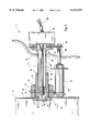
- FIG. 1. is a cross-section showing the preferred sensor probe device in a retracted position outside the chamber.
- FIG. 2. is a cross-section similar to FIG. 1 showing the preferred sensor probe device shown in an extended position within the chamber.
- FIG. 3. is an enlarged isometric view showing the sensor tip of the sensor probe device.
- FIG. 4. is a cross-section similar to FIG. 1 showing an alternate embodiment having an air wipe system attached to the sensor probe device.
- FIG. 5. is a cross-section similar to FIG. 4 showing the alternate embodiment of the present invention in its extended position within the chamber.
- the preferred sensor probe device 1 is shown attached to a wall of a chamber 2.
- the sensor device includes a housing 3, a tubular sleeve 4 and a drive mechanism 5.
- the drive mechanism is provided to either selectively extend or retract sleeve 4 relative to an interior space 6 within the chamber 2.
- the sensor device 1 houses a humidity probe for monitoring the relative humidity inside a corrosion test chamber 2.
- At least one wall 8 of the test chamber includes at least one aperture 9 for receiving the sensor probe device 1, shown attached to the chamber by fixing housing 3 to wall 8 of the chamber.
- Housing 3 includes an elongated portion 10, that extends through aperture 9, and an enlarged end or shoulder 11 that engages the inside surface of the chamber wall 8.
- Housing 3 further includes a threaded section 12 that extends along a length of the elongated portion 10. The threaded section 12 extends outward from shoulder 11, through aperture 9, and is fixed to wall 8 by lock nuts 13.
- the tubular sleeve 4 extends along the inside length of housing 3 and sleeve 4 is sized to provide a sliding fit between the inside surface 3a and outside surface 4a of the housing and sleeve respectively.
- Tubular sleeve 4 further includes an open end 14 for receiving any desired sensor probe, for example in the preferred embodiment a humidity probe 7, and a closed end 16 having a plug 17.
- a plurality of radially spaced apart apertures or slots 18, shown more clearly in FIG. 3, extend through sleeve wall 19 proximate the closed end 16, and the humidity probe 7 is placed within sleeve 4 to position its probe tip 20 adjacent the radially spaced apertures 18. As shown in FIG.
- Sleeve 4 further includes a mounting plate 21 attached to electrical box 22 to connect the sensor probe wires 36 to a programmable controller (not shown) that controls a test program for the chamber.
- At least one air supply 23 is attached to sleeve 4 to inject forced air into the interior space 24 of sleeve 4.
- the air supply line 23 is attached to an air supply (not shown) to inject forced air into space 24.
- the forced air purges any contamination, such as condensation or accumulated solids from the sleeve interior through a sleeve drain 25 located in a lower portion of the sleeve wall.
- the forced air flow also maintains the sensor tip, housed within the probe tip 20, in a dry condition during monitoring of the chamber atmosphere. This insures sending accurate probe signals to the chamber controller.
- the drive mechanism 5 comprises a pneumatic cylinder with its cylinder end 26 attached to the housing 3 via a mounting plate 27 captured between the lock nuts 13 that fasten housing 3 to the chamber wall 8.
- the cylinder piston rod 28 is fastened to plate 38 attached to mounting plate 27 of sleeve 4.
- the pneumatic cylinder arrangement provides one drive means for selectively retracting sleeve 4 from chamber space 6 when the chamber atmosphere isn't being monitored by the probe 7.
- the cylinder is activated to extend its piston rod 28 and withdraw sleeve 4 from the chamber space 6 to a shielded position within housing 3 as shown in FIG. 1.
- the pneumatic cylinder is reversed to extend sleeve 4 outward from its shielded position in housing 3, back into chamber space 6 as shown in FIG. 2.
- any suitable drive mechanism known in the art may be used to extend and retract sleeve 4 without departing from the scope of this invention.
- an electrical solenoid, or a motor and gear arrangement may be substituted for the pneumatic cylinder 5.
- the sensor device 1a includes an air wipe assembly 29 attached to the closed end portion 16 of sleeve 4.
- the air wipe assembly includes a mounting block 30 fastened to plug 17 of sleeve 4, and an air wipe nozzle 31 coupled to mounting block 30 by a threaded fastener as shown at 32, or any other suitable fastener means such as a speed nut.
- An air supply 33 is attached to the air wipe nozzle to selectively bathe the closed end portion of sleeve 4 with a flow of air 34 across apertures 18 to shield the sensitive probe tip 19 from the chamber atmosphere.
- a second air supply 35 is shown extending along the interior length of probe 7 to deliver an additional forced air flow to the sensor tip in end 20 and purge any moisture that may accumulate within the sensor probe 7.
- Air line 35 is also attached to an air supply (not shown) to inject a forced air flow toward the probe tip end 20. This additional air flow further insures that the portion of the wires 36, located inside the probe assembly 7 and 20, are maintained in a dry, clean condition for monitoring operations.
- the second air supply line 35 is attached to electrical box 22, for example by a cable connector. Air line 35 extends through box 22, along the interior length of probe 7, and ends at a location proximate the spliced ends of the probe wires 36 (the sensor tip) located in the sensor tip end portion 20 of the probe assembly.
- Corrosion testing typically includes subjecting selected test specimens through a programmed test cycle where the test chamber environment is controlled by a computer from one test stage to another test stage, for example, through water fog, salt spray, and dry stages.
- the controller is programmed to generate a signal that causes drive mechanism 5 to retract its piston rod 28 and extend sleeve 4 outward from its shielded position within housing 3 and into the chamber space 6, as shown in FIGS. 2 and 5.
- the tip end portion 20 of the humidity probe is exposed to atmospheric conditions within the test chamber by way of the apertures 18 extending through the sleeve wall 19.
- any sensor probe capable of generating an electrical signal can be used to monitor the test chamber space 6, for example, a humidity probe, a temperature probe or the like.
- the sensor probe signals are continually sent from the extended sensor tip in end 20 to a programmable controller through the wires 36 that extend from box 22.
- the programmed controller responds to the generated probe signals by sending a responsive signal to a moisture dispensing device, for example, a water fogger or the like, that adds moisture to the test chamber space 6.
- the controller can be programmed to any predetermined desired humidity level for the dry stage, within a range of say about 30% to 95% relative humidity, and for example, about a 50% preferred relative humidity.
- the chamber controller then maintains the preselected 50% relative humidity by sending a responsive signal that causes the moisture dispensing device to either add or discontinue adding moisture to the interior space 6 of the test chamber.
- the controller can also send a simultaneous signal to the air supply (not shown) to discharge a flow of air from the air wipe nozzle orifice 39 positioned adjacent the closed end of sleeve 4.
- the forced airflow issuing from orifice 39, shown by the arrows 34 in FIG. 5, provides an air wipe that envelops a length of sleeve 4.
- the air wipe flows across the apertures 18 to provide a barrier that prevents the above-mentioned dispensed moisture from entering the sleeve through the apertures where it would contaminate the sensor tip in end 20 housed within the sleeve 4.
- the programmed controller When the programmed corrosion test cycle initiates either a water fog stage where relative humidity is about 100%, or a salt spray stage where relative humidity can be 100% or less, the programmed controller generates a signal that extends piston rod 28 and withdraws sleeve 4 from the interior space 6 and back into a retracted position within housing 3 and outside the chamber as shown in either FIG. 1 or FIG. 4. In its retracted position, sleeve 4 is movably captured within housing 3 and its plug end 17 engages O-ring 37 in housing 3 to seal off and shield the apertures 18, and sensitive tip in end 20, from the now hostile environment within the corrosion test chamber.
- O-ring 37 provides a wiper that removes any salt or moisture that may adhere to the surface of the sleeve as it is being withdrawn back into the housing and thereby further reduces the likelihood of carrying contamination into the housing.
- Sleeve 4 remains in its shielded position within the housing until the test cycle program initiates another dry stage in the test cycle. Then, as before, the controller sends a signal to the drive mechanism 5 to extend movable sleeve 4 back into the test chamber space 6 to control relative humidity during the next dry stage.
Landscapes
- Life Sciences & Earth Sciences (AREA)
- Biodiversity & Conservation Biology (AREA)
- Ecology (AREA)
- Environmental & Geological Engineering (AREA)
- Environmental Sciences (AREA)
- Physics & Mathematics (AREA)
- Health & Medical Sciences (AREA)
- Chemical & Material Sciences (AREA)
- Analytical Chemistry (AREA)
- Biochemistry (AREA)
- General Health & Medical Sciences (AREA)
- General Physics & Mathematics (AREA)
- Immunology (AREA)
- Pathology (AREA)
- Testing Resistance To Weather, Investigating Materials By Mechanical Methods (AREA)
Abstract
Description
Claims (13)
Priority Applications (1)
| Application Number | Priority Date | Filing Date | Title |
|---|---|---|---|
| US09/085,916 US6131473A (en) | 1998-05-28 | 1998-05-28 | Retractable humidity sensor for use in corrosion test chambers |
Applications Claiming Priority (1)
| Application Number | Priority Date | Filing Date | Title |
|---|---|---|---|
| US09/085,916 US6131473A (en) | 1998-05-28 | 1998-05-28 | Retractable humidity sensor for use in corrosion test chambers |
Publications (1)
| Publication Number | Publication Date |
|---|---|
| US6131473A true US6131473A (en) | 2000-10-17 |
Family
ID=22194837
Family Applications (1)
| Application Number | Title | Priority Date | Filing Date |
|---|---|---|---|
| US09/085,916 Expired - Fee Related US6131473A (en) | 1998-05-28 | 1998-05-28 | Retractable humidity sensor for use in corrosion test chambers |
Country Status (1)
| Country | Link |
|---|---|
| US (1) | US6131473A (en) |
Cited By (28)
| Publication number | Priority date | Publication date | Assignee | Title |
|---|---|---|---|---|
| US6435046B1 (en) * | 1999-11-16 | 2002-08-20 | Edward B. Beaver | Monitoring device for a container |
| FR2826113A1 (en) * | 2001-06-18 | 2002-12-20 | Aces Environnement | Implement for sealing and protecting sensors, comprises first ferrule shaped component with internal cavity to receive sensor and second threaded cylindrical section to protect sensor connections |
| US6640658B1 (en) | 2002-06-11 | 2003-11-04 | Signet Scientific Company | Wet-tap sensor assembly and related method |
| US20040140812A1 (en) * | 2003-01-21 | 2004-07-22 | Ademir Scallante | Arrangements containing electrical assemblies and methods of cleaning such electrical assemblies |
| US20050005717A1 (en) * | 2003-07-10 | 2005-01-13 | Pfizer Inc | Probe holder |
| KR100494139B1 (en) * | 2002-11-19 | 2005-06-10 | (주)지엠비 | Holder of electrode pipe for salinometer |
| US20050211281A1 (en) * | 2002-09-09 | 2005-09-29 | Mettler-Toledo Gmbh | Rinsing device for a sensor probe |
| US20060042410A1 (en) * | 2004-09-02 | 2006-03-02 | General Electric Company | Humidity sensor protective shield |
| EP1752763A1 (en) * | 2005-08-10 | 2007-02-14 | Mettler-Toledo AG | Changeover fitting |
| FR2895506A1 (en) * | 2005-12-28 | 2007-06-29 | Intuiskin Soc Par Actions Simp | Measurement device, particularly for physical or chemical variables and parameters, has at least a sensor which on can be extended on a moving part of the device, particularly a telescopic extension |
| US20080173334A1 (en) * | 2006-12-29 | 2008-07-24 | Aibel As | Vessel and methods for calibrating, cleaning or removing an implement located in such a vessel or inserting an implement into such a vessel |
| DE102008046472A1 (en) * | 2008-09-09 | 2010-03-11 | VLM GmbH - Innovative Korrosionsprüftechnik, Labortechnik und Dienstleistungen | Humid climate producing method for testing chamber of wet chemical corrosion testing device, involves determining functions and intensities of components by computer, and automatically setting components to operate/not operate by computer |
| US7806009B2 (en) | 2006-06-23 | 2010-10-05 | Mettler-Toledo Ag | Immersion tube for a measuring probe |
| US20100301060A1 (en) * | 2007-11-27 | 2010-12-02 | Sartorius Stedim Biotech | Connection of an accessory to a vessel |
| DE102009046443A1 (en) * | 2009-11-05 | 2011-05-12 | Endress + Hauser Conducta Gesellschaft für Mess- und Regeltechnik mbH + Co. KG | Change-over device for holding e.g. sensor in process medium in pipe-line of production system to measure pH-value in medium, has crank device provided such that adjustment of lifting pipe is enabled, during increased pressure of medium |
| DE102010038540A1 (en) * | 2010-07-28 | 2012-02-02 | Endress + Hauser Flowtec Ag | Retractable housing |
| US20120097557A1 (en) * | 2009-06-16 | 2012-04-26 | Sartorius Stedim Biotech Gmbh | Container having a sensor adapter |
| WO2014035701A1 (en) * | 2012-08-30 | 2014-03-06 | United Technologies Corporation | Tip clearance probe for turbine applications |
| US20150276456A1 (en) * | 2014-03-28 | 2015-10-01 | Parker-Hannifin Corporation | Through wall installation of sensors in fuel tanks |
| US9964530B2 (en) * | 2016-03-07 | 2018-05-08 | Tracy William Baldaccini | Confined space entry station |
| CN108020630A (en) * | 2016-11-01 | 2018-05-11 | 华北电力大学(保定) | A kind of steam turbine last stage humidity detector and steam turbine |
| CN111610295A (en) * | 2020-06-09 | 2020-09-01 | 黄文书 | A kind of tea garden environment monitoring equipment |
| CN112067762A (en) * | 2020-09-07 | 2020-12-11 | 上海云隐科技有限公司 | Granary humidity transducer with protect function |
| GB2601813A (en) * | 2020-12-11 | 2022-06-15 | The Leeds And Bradford Boiler Company Ltd | Device and method of testing |
| US20220373496A1 (en) * | 2021-05-21 | 2022-11-24 | Rosemount Inc. | Sanitary single-use process connection with integral wet storage for use with process sensors |
| CN116429980A (en) * | 2023-04-21 | 2023-07-14 | 滨州学院 | A chemical gas monitoring device |
| CN117225761A (en) * | 2023-10-17 | 2023-12-15 | 湖南绿科环保科技有限公司 | Maintenance-free oil smoke monitoring probe self-cleaning system |
| CN120486348A (en) * | 2025-07-16 | 2025-08-15 | 福建农林大学 | Static sounding probe and method for in-situ evaluation of carbon in soil |
Citations (23)
| Publication number | Priority date | Publication date | Assignee | Title |
|---|---|---|---|---|
| US3007340A (en) * | 1958-09-08 | 1961-11-07 | Leeds & Northrup Co | Measuring system |
| US3259466A (en) * | 1962-12-28 | 1966-07-05 | Gen Motors Corp | Corrosive vapor test chamber |
| US3643508A (en) * | 1969-12-15 | 1972-02-22 | Dango & Dienenthal Kg | Device for removing gas and furnace charge probes from shaft furnaces and/or for taking temperature and gas pressure measurements in the interior space of the furnace |
| US3813943A (en) * | 1972-03-03 | 1974-06-04 | Bethlehem Steel Corp | Apparatus for inserting an expendable sensor into a basic oxygen furnace |
| US3832882A (en) * | 1973-05-10 | 1974-09-03 | Us Navy | Humidity testing apparatus |
| US4075035A (en) * | 1975-01-17 | 1978-02-21 | Institut De Recherches De La Siderurgie Francaise (Irsid) | Temperature detecting device for a furnace |
| US4275592A (en) * | 1979-01-05 | 1981-06-30 | Mcmurry-Hughes, Inc. | Extractor tool and holder |
| US4327586A (en) * | 1979-09-10 | 1982-05-04 | Redland Automation Limited | Stuffing box for introducing instrument into high pressure conduit |
| US4346611A (en) * | 1980-12-19 | 1982-08-31 | Welker Robert H | Insertion regulator for pressurized pipelines |
| US4404284A (en) * | 1980-12-17 | 1983-09-13 | Vogelbusch Gesellschaft M.B.H. | Measurement of volatile constituents of a culture medium |
| US4471664A (en) * | 1981-01-23 | 1984-09-18 | Paul Wurth S.A. | Support for a blast furnace probe |
| JPS61137056A (en) * | 1985-07-25 | 1986-06-24 | Ngk Insulators Ltd | Oxygen sensor |
| US4794804A (en) * | 1987-02-19 | 1989-01-03 | Kabushiki-Kaisha Toyo Seisakusho | Salt damage environmental testing chamber for self-propelled vehicles |
| US4889483A (en) * | 1984-09-06 | 1989-12-26 | Granco-Clark, Inc. | Temperature controlled probe assembly |
| JPH03105212A (en) * | 1989-09-20 | 1991-05-02 | Tokico Ltd | Insertion type sensor |
| SU1659783A1 (en) * | 1988-05-16 | 1991-06-30 | Всесоюзный Научно-Исследовательский Биотехнический Институт | Device for analyzing air in gas ducts |
| US5042294A (en) * | 1988-07-11 | 1991-08-27 | Ken Uzzell | Moisture detection probe |
| US5294048A (en) * | 1991-10-18 | 1994-03-15 | Matsushita Seiko Co., Ltd. | Apparatus for controlling ventilation fan |
| US5385060A (en) * | 1990-12-03 | 1995-01-31 | Wang; Kjetil | Device for the assembly or disassembly of probes in process pipes, tanks, etc. |
| US5484008A (en) * | 1994-08-26 | 1996-01-16 | Howmet Corporation | Thermocouple positioner for directional solidification apparatus/process |
| US5487532A (en) * | 1993-05-27 | 1996-01-30 | Paul Wurth S.A. | Device for inserting a lance into a pressurized container, in particular a blast furnace |
| US5824918A (en) * | 1997-02-14 | 1998-10-20 | The Singleton Corporation | Relative humidity control system for corrosion test chamber |
| US5922939A (en) * | 1997-03-07 | 1999-07-13 | Veris Industries, Inc. | Humidity sensor |
-
1998
- 1998-05-28 US US09/085,916 patent/US6131473A/en not_active Expired - Fee Related
Patent Citations (23)
| Publication number | Priority date | Publication date | Assignee | Title |
|---|---|---|---|---|
| US3007340A (en) * | 1958-09-08 | 1961-11-07 | Leeds & Northrup Co | Measuring system |
| US3259466A (en) * | 1962-12-28 | 1966-07-05 | Gen Motors Corp | Corrosive vapor test chamber |
| US3643508A (en) * | 1969-12-15 | 1972-02-22 | Dango & Dienenthal Kg | Device for removing gas and furnace charge probes from shaft furnaces and/or for taking temperature and gas pressure measurements in the interior space of the furnace |
| US3813943A (en) * | 1972-03-03 | 1974-06-04 | Bethlehem Steel Corp | Apparatus for inserting an expendable sensor into a basic oxygen furnace |
| US3832882A (en) * | 1973-05-10 | 1974-09-03 | Us Navy | Humidity testing apparatus |
| US4075035A (en) * | 1975-01-17 | 1978-02-21 | Institut De Recherches De La Siderurgie Francaise (Irsid) | Temperature detecting device for a furnace |
| US4275592A (en) * | 1979-01-05 | 1981-06-30 | Mcmurry-Hughes, Inc. | Extractor tool and holder |
| US4327586A (en) * | 1979-09-10 | 1982-05-04 | Redland Automation Limited | Stuffing box for introducing instrument into high pressure conduit |
| US4404284A (en) * | 1980-12-17 | 1983-09-13 | Vogelbusch Gesellschaft M.B.H. | Measurement of volatile constituents of a culture medium |
| US4346611A (en) * | 1980-12-19 | 1982-08-31 | Welker Robert H | Insertion regulator for pressurized pipelines |
| US4471664A (en) * | 1981-01-23 | 1984-09-18 | Paul Wurth S.A. | Support for a blast furnace probe |
| US4889483A (en) * | 1984-09-06 | 1989-12-26 | Granco-Clark, Inc. | Temperature controlled probe assembly |
| JPS61137056A (en) * | 1985-07-25 | 1986-06-24 | Ngk Insulators Ltd | Oxygen sensor |
| US4794804A (en) * | 1987-02-19 | 1989-01-03 | Kabushiki-Kaisha Toyo Seisakusho | Salt damage environmental testing chamber for self-propelled vehicles |
| SU1659783A1 (en) * | 1988-05-16 | 1991-06-30 | Всесоюзный Научно-Исследовательский Биотехнический Институт | Device for analyzing air in gas ducts |
| US5042294A (en) * | 1988-07-11 | 1991-08-27 | Ken Uzzell | Moisture detection probe |
| JPH03105212A (en) * | 1989-09-20 | 1991-05-02 | Tokico Ltd | Insertion type sensor |
| US5385060A (en) * | 1990-12-03 | 1995-01-31 | Wang; Kjetil | Device for the assembly or disassembly of probes in process pipes, tanks, etc. |
| US5294048A (en) * | 1991-10-18 | 1994-03-15 | Matsushita Seiko Co., Ltd. | Apparatus for controlling ventilation fan |
| US5487532A (en) * | 1993-05-27 | 1996-01-30 | Paul Wurth S.A. | Device for inserting a lance into a pressurized container, in particular a blast furnace |
| US5484008A (en) * | 1994-08-26 | 1996-01-16 | Howmet Corporation | Thermocouple positioner for directional solidification apparatus/process |
| US5824918A (en) * | 1997-02-14 | 1998-10-20 | The Singleton Corporation | Relative humidity control system for corrosion test chamber |
| US5922939A (en) * | 1997-03-07 | 1999-07-13 | Veris Industries, Inc. | Humidity sensor |
Non-Patent Citations (5)
| Title |
|---|
| Liebisch Drawing No. 20107 1, Mar.13, 1991, Drawing No. 20107 11, Mar. 12, 1991, and attached Liebisch LEGENDE Seitenzahl (page No.) 6 and 9 dated Mar. 1, 1991. * |
| Liebisch Drawing No. 20107-1, Mar.13, 1991, Drawing No. 20107-11, Mar. 12, 1991, and attached Liebisch LEGENDE Seitenzahl (page No.) 6 and 9 dated Mar. 1, 1991. |
| Operating Instructions, Hygromess Transmitters, No. 0111,0600, Revision 03/88 pp. 1 28. * |
| Operating Instructions, Hygromess-Transmitters, No. 0111,0600, Revision 03/88 pp. 1-28. |
| The Harshaw Chemical Co. undated drawing labeled Exhibit A and considered by Applicant on p. 2, starting at line 3 of the specification. Published by, approximated, 1987 Month not given. * |
Cited By (45)
| Publication number | Priority date | Publication date | Assignee | Title |
|---|---|---|---|---|
| US6435046B1 (en) * | 1999-11-16 | 2002-08-20 | Edward B. Beaver | Monitoring device for a container |
| FR2826113A1 (en) * | 2001-06-18 | 2002-12-20 | Aces Environnement | Implement for sealing and protecting sensors, comprises first ferrule shaped component with internal cavity to receive sensor and second threaded cylindrical section to protect sensor connections |
| US6640658B1 (en) | 2002-06-11 | 2003-11-04 | Signet Scientific Company | Wet-tap sensor assembly and related method |
| US7325555B2 (en) * | 2002-09-09 | 2008-02-05 | Mettler-Toledo Ag | Rinsing device for a sensor probe |
| US20050211281A1 (en) * | 2002-09-09 | 2005-09-29 | Mettler-Toledo Gmbh | Rinsing device for a sensor probe |
| KR100494139B1 (en) * | 2002-11-19 | 2005-06-10 | (주)지엠비 | Holder of electrode pipe for salinometer |
| US20040140812A1 (en) * | 2003-01-21 | 2004-07-22 | Ademir Scallante | Arrangements containing electrical assemblies and methods of cleaning such electrical assemblies |
| US20050005717A1 (en) * | 2003-07-10 | 2005-01-13 | Pfizer Inc | Probe holder |
| US20060042410A1 (en) * | 2004-09-02 | 2006-03-02 | General Electric Company | Humidity sensor protective shield |
| EP1752763A1 (en) * | 2005-08-10 | 2007-02-14 | Mettler-Toledo AG | Changeover fitting |
| JP2007047163A (en) * | 2005-08-10 | 2007-02-22 | Mettler-Toledo Ag | Holder armature for replaceable measuring probe |
| US20070034028A1 (en) * | 2005-08-10 | 2007-02-15 | Mettler-Toledo Ag | Holder armature for an interchangeable measuring probe |
| CN1912402B (en) * | 2005-08-10 | 2012-09-05 | 梅特勒-托莱多股份公司 | Holder armature for an interchangeable measuring probe |
| US7594449B2 (en) | 2005-08-10 | 2009-09-29 | Mettler-Toledo Ag | Holder armature for an interchangeable measuring probe |
| FR2895506A1 (en) * | 2005-12-28 | 2007-06-29 | Intuiskin Soc Par Actions Simp | Measurement device, particularly for physical or chemical variables and parameters, has at least a sensor which on can be extended on a moving part of the device, particularly a telescopic extension |
| WO2007074255A1 (en) * | 2005-12-28 | 2007-07-05 | Intuiskin | Miniature measuring device |
| US20090024361A1 (en) * | 2005-12-28 | 2009-01-22 | Intuiskin | Miniature measuring device |
| US7806009B2 (en) | 2006-06-23 | 2010-10-05 | Mettler-Toledo Ag | Immersion tube for a measuring probe |
| US20080173334A1 (en) * | 2006-12-29 | 2008-07-24 | Aibel As | Vessel and methods for calibrating, cleaning or removing an implement located in such a vessel or inserting an implement into such a vessel |
| US8082933B2 (en) * | 2006-12-29 | 2011-12-27 | Hamworthy Plc | Vessel and methods for calibrating, cleaning or removing an implement located in such a vessel or inserting an implement into such a vessel |
| US20100301060A1 (en) * | 2007-11-27 | 2010-12-02 | Sartorius Stedim Biotech | Connection of an accessory to a vessel |
| US8631716B2 (en) * | 2007-11-27 | 2014-01-21 | Sartorius Stedim Biotech | Connection of an accessory to a vessel |
| DE102008046472A1 (en) * | 2008-09-09 | 2010-03-11 | VLM GmbH - Innovative Korrosionsprüftechnik, Labortechnik und Dienstleistungen | Humid climate producing method for testing chamber of wet chemical corrosion testing device, involves determining functions and intensities of components by computer, and automatically setting components to operate/not operate by computer |
| DE102008046472B4 (en) * | 2008-09-09 | 2013-08-22 | VLM GmbH - Innovative Korrosionsprüftechnik, Labortechnik und Dienstleistungen | Method and device for producing humid climates |
| US20120097557A1 (en) * | 2009-06-16 | 2012-04-26 | Sartorius Stedim Biotech Gmbh | Container having a sensor adapter |
| US9103703B2 (en) * | 2009-06-16 | 2015-08-11 | Sartorius Stedim Biotech Gmbh | Container having a sensor adapter |
| EP2443420B1 (en) * | 2009-06-16 | 2016-02-10 | Sartorius Stedim Biotech GmbH | Container with a sensor adapter |
| DE102009046443A1 (en) * | 2009-11-05 | 2011-05-12 | Endress + Hauser Conducta Gesellschaft für Mess- und Regeltechnik mbH + Co. KG | Change-over device for holding e.g. sensor in process medium in pipe-line of production system to measure pH-value in medium, has crank device provided such that adjustment of lifting pipe is enabled, during increased pressure of medium |
| DE102010038540A1 (en) * | 2010-07-28 | 2012-02-02 | Endress + Hauser Flowtec Ag | Retractable housing |
| US9027915B2 (en) | 2010-07-28 | 2015-05-12 | Endress + Hauser Flowtec Ag | Retractable assembly |
| WO2014035701A1 (en) * | 2012-08-30 | 2014-03-06 | United Technologies Corporation | Tip clearance probe for turbine applications |
| US10139261B2 (en) * | 2014-03-28 | 2018-11-27 | Parker-Hannifin Corporation | Through wall installation of sensors in fuel tanks |
| US20150276456A1 (en) * | 2014-03-28 | 2015-10-01 | Parker-Hannifin Corporation | Through wall installation of sensors in fuel tanks |
| US9964530B2 (en) * | 2016-03-07 | 2018-05-08 | Tracy William Baldaccini | Confined space entry station |
| CN108020630B (en) * | 2016-11-01 | 2023-09-12 | 华北电力大学(保定) | A steam turbine final stage humidity detection device and steam turbine |
| CN108020630A (en) * | 2016-11-01 | 2018-05-11 | 华北电力大学(保定) | A kind of steam turbine last stage humidity detector and steam turbine |
| CN111610295A (en) * | 2020-06-09 | 2020-09-01 | 黄文书 | A kind of tea garden environment monitoring equipment |
| CN111610295B (en) * | 2020-06-09 | 2022-06-07 | 杭州径山茶叶有限公司 | Tea garden environment monitoring equipment |
| CN112067762A (en) * | 2020-09-07 | 2020-12-11 | 上海云隐科技有限公司 | Granary humidity transducer with protect function |
| GB2601813A (en) * | 2020-12-11 | 2022-06-15 | The Leeds And Bradford Boiler Company Ltd | Device and method of testing |
| GB2601813B (en) * | 2020-12-11 | 2025-04-16 | The Leeds And Bradford Boiler Company Ltd | Device and method for testing |
| US20220373496A1 (en) * | 2021-05-21 | 2022-11-24 | Rosemount Inc. | Sanitary single-use process connection with integral wet storage for use with process sensors |
| CN116429980A (en) * | 2023-04-21 | 2023-07-14 | 滨州学院 | A chemical gas monitoring device |
| CN117225761A (en) * | 2023-10-17 | 2023-12-15 | 湖南绿科环保科技有限公司 | Maintenance-free oil smoke monitoring probe self-cleaning system |
| CN120486348A (en) * | 2025-07-16 | 2025-08-15 | 福建农林大学 | Static sounding probe and method for in-situ evaluation of carbon in soil |
Similar Documents
| Publication | Publication Date | Title |
|---|---|---|
| US6131473A (en) | Retractable humidity sensor for use in corrosion test chambers | |
| US4668479A (en) | Plasma processing apparatus | |
| US5563737A (en) | Arrangement for cleaning an optical window in a process | |
| JPH05208157A (en) | Dispenser | |
| JP4947452B1 (en) | Method for measuring thread elements at the end of pipes | |
| US4148271A (en) | Incipient bearing failure indicator | |
| US20240246124A1 (en) | Apparatus and methods for exhaust cleaning | |
| US6058776A (en) | Conductivity metering device | |
| CA2539208C (en) | Method and apparatus for determining operational condition of pollution monitoring equipment | |
| US5150065A (en) | Flexible holder for a corrosion-detecting coupon | |
| US6235123B1 (en) | Chemical cleaning system for electrodes used in a liquid environment | |
| ES3057740T3 (en) | A method and system for early fault detection in a wind turbine generator | |
| US12085498B2 (en) | Corrosion testing device | |
| KR102613127B1 (en) | Descaling device adhered in a tube by a vibrator rotating by a pneumatic system and a wire attached thereto | |
| CN101495851A (en) | Optical measurement probe for process monitoring | |
| US4073029A (en) | Parts cleaner | |
| CA2205419A1 (en) | Replaceable consumable erosion detector | |
| JP4866856B2 (en) | Dryer and method of controlling the dryer | |
| JPH0523625B2 (en) | ||
| KR810001460Y1 (en) | Washing equipment of the quality of water detector | |
| JP2011203220A (en) | Screw element measuring method of tube end | |
| KR100338411B1 (en) | System for replicating tissue of metal | |
| KR102928288B1 (en) | Automatic hole abrasion type concrete carbonation indicating tester | |
| KR102928281B1 (en) | Hole abrasion type concrete carbonation indicating tester | |
| US2979951A (en) | Temperature sensing apparatus |
Legal Events
| Date | Code | Title | Description |
|---|---|---|---|
| AS | Assignment |
Owner name: BETHLEHEM STEEL CORPORATION, PENNSYLVANIA Free format text: ASSIGNMENT OF ASSIGNORS INTEREST;ASSIGNORS:HOFFMAN, JAY D.;TOWNSEND, HERBERT E.;REEL/FRAME:009216/0568 Effective date: 19980521 |
|
| AS | Assignment |
Owner name: ISG TECHNOLOGIES, INC., OHIO Free format text: ASSIGNMENT OF ASSIGNORS INTEREST;ASSIGNOR:BETHLEHEM STEEL CORPORATION;REEL/FRAME:014033/0881 Effective date: 20030506 |
|
| AS | Assignment |
Owner name: CIT GROUP/BUSINESS CREDIT, INC., AS COLLATERAL AGE Free format text: PLEDGE AND SECURITY AGREEMENT;ASSIGNOR:INTERNATIONAL STEEL GROUP, INC.;REEL/FRAME:013663/0415 Effective date: 20030507 |
|
| FPAY | Fee payment |
Year of fee payment: 4 |
|
| AS | Assignment |
Owner name: ISG/EGL HOLDING COMPANY, OHIO Free format text: RELEASE BY SECURED PARTY;ASSIGNOR:THE CIT GROUP/BUSINESS CREDIT, INC., AS COLLATERAL AGENT;REEL/FRAME:019432/0170 Effective date: 20070613 Owner name: ISG PIEDMONT INC., OHIO Free format text: RELEASE BY SECURED PARTY;ASSIGNOR:THE CIT GROUP/BUSINESS CREDIT, INC., AS COLLATERAL AGENT;REEL/FRAME:019432/0170 Effective date: 20070613 Owner name: ISG WARREN INC., OHIO Free format text: RELEASE BY SECURED PARTY;ASSIGNOR:THE CIT GROUP/BUSINESS CREDIT, INC., AS COLLATERAL AGENT;REEL/FRAME:019432/0170 Effective date: 20070613 Owner name: ISG RAILWAYS, INC., OHIO Free format text: RELEASE BY SECURED PARTY;ASSIGNOR:THE CIT GROUP/BUSINESS CREDIT, INC., AS COLLATERAL AGENT;REEL/FRAME:019432/0170 Effective date: 20070613 Owner name: ISG HIBBING, INC., OHIO Free format text: RELEASE BY SECURED PARTY;ASSIGNOR:THE CIT GROUP/BUSINESS CREDIT, INC., AS COLLATERAL AGENT;REEL/FRAME:019432/0170 Effective date: 20070613 Owner name: ISG ACQUISITION INC., OHIO Free format text: RELEASE BY SECURED PARTY;ASSIGNOR:THE CIT GROUP/BUSINESS CREDIT, INC., AS COLLATERAL AGENT;REEL/FRAME:019432/0170 Effective date: 20070613 Owner name: ISG CLEVELAND INC., OHIO Free format text: RELEASE BY SECURED PARTY;ASSIGNOR:THE CIT GROUP/BUSINESS CREDIT, INC., AS COLLATERAL AGENT;REEL/FRAME:019432/0170 Effective date: 20070613 Owner name: ISG INDIANA HARBOR INC., OHIO Free format text: RELEASE BY SECURED PARTY;ASSIGNOR:THE CIT GROUP/BUSINESS CREDIT, INC., AS COLLATERAL AGENT;REEL/FRAME:019432/0170 Effective date: 20070613 Owner name: ISG LACKAWANNA INC., OHIO Free format text: RELEASE BY SECURED PARTY;ASSIGNOR:THE CIT GROUP/BUSINESS CREDIT, INC., AS COLLATERAL AGENT;REEL/FRAME:019432/0170 Effective date: 20070613 Owner name: ISG RIVERDALE INC., OHIO Free format text: RELEASE BY SECURED PARTY;ASSIGNOR:THE CIT GROUP/BUSINESS CREDIT, INC., AS COLLATERAL AGENT;REEL/FRAME:019432/0170 Effective date: 20070613 Owner name: ISG SPARROWS POINT INC., OHIO Free format text: RELEASE BY SECURED PARTY;ASSIGNOR:THE CIT GROUP/BUSINESS CREDIT, INC., AS COLLATERAL AGENT;REEL/FRAME:019432/0170 Effective date: 20070613 Owner name: ISG CLEVELAND WEST, INC., OHIO Free format text: RELEASE BY SECURED PARTY;ASSIGNOR:THE CIT GROUP/BUSINESS CREDIT, INC., AS COLLATERAL AGENT;REEL/FRAME:019432/0170 Effective date: 20070613 Owner name: ISG BURNS HARBOR INC., OHIO Free format text: RELEASE BY SECURED PARTY;ASSIGNOR:THE CIT GROUP/BUSINESS CREDIT, INC., AS COLLATERAL AGENT;REEL/FRAME:019432/0170 Effective date: 20070613 Owner name: ISG CLEVELAND WEST PROPERTIES, INC., OHIO Free format text: RELEASE BY SECURED PARTY;ASSIGNOR:THE CIT GROUP/BUSINESS CREDIT, INC., AS COLLATERAL AGENT;REEL/FRAME:019432/0170 Effective date: 20070613 Owner name: ISG PLATE INC., OHIO Free format text: RELEASE BY SECURED PARTY;ASSIGNOR:THE CIT GROUP/BUSINESS CREDIT, INC., AS COLLATERAL AGENT;REEL/FRAME:019432/0170 Effective date: 20070613 Owner name: ISG STEELTON INC., OHIO Free format text: RELEASE BY SECURED PARTY;ASSIGNOR:THE CIT GROUP/BUSINESS CREDIT, INC., AS COLLATERAL AGENT;REEL/FRAME:019432/0170 Effective date: 20070613 Owner name: ISG SOUTH CHICAGO & INDIANA HARBOR RAILWAY COMPANY Free format text: RELEASE BY SECURED PARTY;ASSIGNOR:THE CIT GROUP/BUSINESS CREDIT, INC., AS COLLATERAL AGENT;REEL/FRAME:019432/0170 Effective date: 20070613 Owner name: ISG VENTURE, INC., OHIO Free format text: RELEASE BY SECURED PARTY;ASSIGNOR:THE CIT GROUP/BUSINESS CREDIT, INC., AS COLLATERAL AGENT;REEL/FRAME:019432/0170 Effective date: 20070613 Owner name: INTERNATIONAL STEEL GROUP, INC., OHIO Free format text: RELEASE BY SECURED PARTY;ASSIGNOR:THE CIT GROUP/BUSINESS CREDIT, INC., AS COLLATERAL AGENT;REEL/FRAME:019432/0170 Effective date: 20070613 Owner name: ISG CLEVELAND WORKS RAILWAY COMPANY, OHIO Free format text: RELEASE BY SECURED PARTY;ASSIGNOR:THE CIT GROUP/BUSINESS CREDIT, INC., AS COLLATERAL AGENT;REEL/FRAME:019432/0170 Effective date: 20070613 Owner name: ISG TECHNOLOGIES, INC., OHIO Free format text: RELEASE BY SECURED PARTY;ASSIGNOR:THE CIT GROUP/BUSINESS CREDIT, INC., AS COLLATERAL AGENT;REEL/FRAME:019432/0170 Effective date: 20070613 Owner name: ISG SALES, INC., OHIO Free format text: RELEASE BY SECURED PARTY;ASSIGNOR:THE CIT GROUP/BUSINESS CREDIT, INC., AS COLLATERAL AGENT;REEL/FRAME:019432/0170 Effective date: 20070613 Owner name: BETHLEHEM HIBBING CORPORATION, OHIO Free format text: RELEASE BY SECURED PARTY;ASSIGNOR:THE CIT GROUP/BUSINESS CREDIT, INC., AS COLLATERAL AGENT;REEL/FRAME:019432/0170 Effective date: 20070613 Owner name: ISG HENNEPIN, INC., OHIO Free format text: RELEASE BY SECURED PARTY;ASSIGNOR:THE CIT GROUP/BUSINESS CREDIT, INC., AS COLLATERAL AGENT;REEL/FRAME:019432/0170 Effective date: 20070613 |
|
| REMI | Maintenance fee reminder mailed | ||
| LAPS | Lapse for failure to pay maintenance fees | ||
| STCH | Information on status: patent discontinuation |
Free format text: PATENT EXPIRED DUE TO NONPAYMENT OF MAINTENANCE FEES UNDER 37 CFR 1.362 |
|
| FP | Lapsed due to failure to pay maintenance fee |
Effective date: 20081017 |