US6120104A - Wheel cover - Google Patents
Wheel cover Download PDFInfo
- Publication number
- US6120104A US6120104A US08/944,893 US94489397A US6120104A US 6120104 A US6120104 A US 6120104A US 94489397 A US94489397 A US 94489397A US 6120104 A US6120104 A US 6120104A
- Authority
- US
- United States
- Prior art keywords
- wheel cover
- cover body
- wheel
- movable member
- center
- Prior art date
- Legal status (The legal status is an assumption and is not a legal conclusion. Google has not performed a legal analysis and makes no representation as to the accuracy of the status listed.)
- Expired - Fee Related
Links
Images


Classifications
-
- B—PERFORMING OPERATIONS; TRANSPORTING
- B60—VEHICLES IN GENERAL
- B60B—VEHICLE WHEELS; CASTORS; AXLES FOR WHEELS OR CASTORS; INCREASING WHEEL ADHESION
- B60B7/00—Wheel cover discs, rings, or the like, for ornamenting, protecting, venting, or obscuring, wholly or in part, the wheel body, rim, hub, or tyre sidewall, e.g. wheel cover discs, wheel cover discs with cooling fins
- B60B7/20—Wheel cover discs, rings, or the like, for ornamenting, protecting, venting, or obscuring, wholly or in part, the wheel body, rim, hub, or tyre sidewall, e.g. wheel cover discs, wheel cover discs with cooling fins having an element mounted for rotation independently of wheel rotation
-
- G—PHYSICS
- G09—EDUCATION; CRYPTOGRAPHY; DISPLAY; ADVERTISING; SEALS
- G09F—DISPLAYING; ADVERTISING; SIGNS; LABELS OR NAME-PLATES; SEALS
- G09F21/00—Mobile visual advertising
- G09F21/04—Mobile visual advertising by land vehicles
- G09F21/045—Mobile visual advertising by land vehicles supported by the wheels
Definitions
- the present invention relates to a wheel cover for automobile e.g a passenger car, a truck, or a bus.
- a conventional wheel cover comprises a wheel cover body covering the disc part of wheel and a multiplicity of fitting pieces forming the wheel cover body, fitably fixed to the disc part or rim of the wheel.
- the conventional wheel cover is fitably fixed to the disc part or rim of the wheel with the multiplicity of fitting piece. Therefore, people cannot see the design drawn on the wheel cover body because the wheel cover body rotates with the wheel as one during running.
- FIG. 1 is a perspective view from a back side showing a first embodiment of the present invention
- FIG. 2 is a vertical cross-sectional view showing a first embodiment of the present invention
- FIG. 3 is an explanation view of a fixable side fixture showing a first embodiment of the present invention
- FIG. 4 is an explanation view of a movable side fixture showing a first embodiment of the present invention
- FIG. 5 is a front view of a wheel cover body showing a first embodiment of the present invention
- FIG. 6 is a perspective view from a back side of a wheel cover body showing a first embodiment of the present invention
- FIG. 7 is a sectional view taken on line 7--7 of FIG. 5;
- FIG. 8 is an explanation view showing the condition of a movable side fixture mounted to a fixable side fixture
- FIG. 9 is an explanation view showing the condition of a fixable side fixture mounted to a wheel
- FIG. 10 is an explanation view showing the condition mounted a wheel cover body to a movable side fixture
- FIG. 11 is a cross-sectional view showing the condition of a wheel cover body to a movable side fixture mounted
- FIG. 12 is an explanation view during use showing a first embodiment of the present invention.
- FIG. 13 is an explanation view indicating a flow of an air current during use showing a first embodiment of the present invention
- FIG. 14 is a front view showing a second embodiment of the present invention.
- FIG. 15 is a vertical cross-sectional view showing a second embodiment of the present invention.
- FIG. 16 is an explanation view of a condition separated from a wheel cover body and a movable side fixture
- FIG. 17 is a perspective view from a back side showing a third embodiment of the present invention.
- FIG. 18 is a perspective view of a fixable side fixture showing a third embodiment of the present invention.
- FIG. 19 is a partly cross-sectional front view of a mounted condition showing a third embodiment of the present invention.
- FIG. 20 is a cross-sectional view of a condition during use showing a fourth embodiment of the present invention.
- FIG. 21 is a mainly expanded cross-sectional view showing a fourth embodiment of the present invention.
- FIG. 22 is a partly cross-sectional exploded perspective view of a fixable side fixture and a movable side fixture
- FIG. 23 is a perspective view of a back side showing a fifth embodiment of the present invention.
- FIG. 24 is a cross-sectional view showing a fifth embodiment of the present invention.
- FIG. 25 is a front view of a wheel cover body showing a fifth embodiment of the present invention.
- FIG. 26 is a front view showing a sixth embodiment of the present invention.
- FIG. 27 is a cross-sectional view showing a sixth embodiment of the present invention.
- FIG. 28 is a mainly expanded cross-sectional view showing a sixth embodiment of the present invention.
- FIG. 29 is a perspective view of back side showing a seventh embodiment of the present invention.
- FIG. 30 is a cross-sectional view showing a seventh embodiment of the present invention.
- FIG. 31 is a partly cross-sectional explanation view separated from a wheel cover body and a movable side fixture
- FIG. 32 is a perspective view of back side showing an eighth embodiment of the present invention.
- FIG. 33 is an explanation view of a condition during use showing an eighth embodiment of the present invention.
- FIG. 34 is a perspective view of a condition during use showing an eighth embodiment of the present invention.
- FIG. 35 is a perspective view of a back side showing a ninth embodiment of the present invention.
- FIG. 36 is a front view showing a ninth embodiment of the present invention.
- FIG. 37 is a cross-sectional view of a condition during use showing a ninth embodiment of the present invention.
- FIG. 38 is a perspective view of back side showing a tenth embodiment of the present invention.
- FIG. 39 is a front view showing a tenth embodiment of the present invention.
- FIG. 40 is a cross-sectional view of a condition during use showing a tenth embodiment of the present invention.
- FIG. 41 is a perspective view of back side showing an eleventh embodiment of the present invention.
- FIG. 42 is a cross-sectional view of a wheel cover body showing an eleventh embodiment of the present invention.
- FIG. 43 is a cross-sectional view of a condition during use showing an eleventh embodiment of the present invention.
- FIG. 44 is a cross-sectional view of a condition during use showing a twelfth embodiment of the present invention.
- FIG. 45 is a mainly expanded cross-sectional view showing a twelfth embodiment of the present invention.
- FIG. 46 is an exploded perspective view showing a twelfth embodiment of the present invention.
- FIG. 47 is an explanation view of a using condition showing a thirteenth embodiment of the present invention.
- FIG. 48 is a cross-sectional view of a condition during use showing a thirteenth embodiment of the present invention.
- FIG. 49 is a partly cross-sectional exploded perspective view showing a thirteenth embodiment of the present invention.
- FIG. 50 is a perspective view from a back side showing a fourteenth embodiment of the present invention.
- FIG. 51 is a vartical cross-sectional view showing a fourteenth embodiment of the present invention.
- FIG. 52 is an explanation view of a nonreturn protection showing a fourteenth embodiment of the present invention.
- FIG. 53 is a exploded view for explanation about a nonreturn protection showing a fourteenth embodiment of the present invention.
- FIG. 54 is a perspective view of back side showing a fifteenth embodiment of the present invention.
- FIG. 55 is an explanation view of a fitting member showing a fifteenth embodiment of the present invention.
- FIG. 56 is an explanation view about a mounted condition of a fitting member showing a fifteenth embodiment of the present invention.
- FIG. 57 is an explanation view about a mounted condition to the other way of a fitting member showing a fifteenth embodiment of the present invention.
- FIG. 58 is a perspective view from back side showing a sixteenth embodiment of the present invention.
- FIG. 59 is an explanation view of an fitting member showing a sixteenth embodiment of the present invention.
- FIG. 60 is a mounted explanation view of a movable side fixture showing a sixteenth embodiment of the present invention.
- FIG. 61 is a cross-sectional view taken on the line 61--61 of FIG. 60;
- FIG. 62 is a cross-sectional view taken on the line 62--62 of FIG. 60;
- FIG. 63 is an explanation view of a removing condition showing a sixteenth embodiment of the present invention.
- FIG. 64 is a perspective view from back side showing a seventeenth embodiment of the present invention.
- FIG. 65 is a mounting explanation view of a movable side fixture showing a seventeenth embodiment of the present invention.
- FIG. 66 is a perspective view taken on the line 66--66 of FIG. 65;
- FIG. 67 is a perspective view from back side showing an eighteenth embodimentof the present invention.
- FIG. 68 is an explanation view of a fitting member showing an eighteenth embodiment of the present invention.
- FIG. 69 is a mounting explanation view of a movable side fixture showing an eighteenth embodiment of the present invention.
- FIG. 70 is a cross-sectional view taken on the line 70--70 of FIG. 69.
- FIG. 71 is an explanation view of a removing condition showing an eighteenth embodiment of the present invention.
- FIGS. 1 to 13 illustrate a first embodiment of the present invention wherein a wheel cover 1 is mounted to a wheel 3 of the automobiles e. g. a trunk, a bus, a car, and wherein a passenger car 2 is elected in this embodiment.
- the wheel cover 1 comprises a fixable side fixture 4, a movable side fixture 6 and a wheel cover body 7 in the shape of disc.
- the fixable side fixture 4 is fixably mounted at a place that the central part of the fixable side fixture 4 can be positioned to the center of the wheel 3.
- the side fixture 6 is rotatably mounted to the central part of the fixable side fixture 4 through a bearing 5.
- the wheel cover body 7 is mounted to the movable side fixture 6 while the wheel cover body 7 has a space between the wheel 3.
- the fixable side fixture 4 comprises a fixable side fixture body 10 and an axle insertable hole 11.
- wheel bolt insertable holes 9, 9 formed at both sides thereof receive wheel bolts 8, 8 inserted therein selectively of vis-a-vis even number of wheel bolts 8 are able to be fixed to the wheel 3.
- the fixable side fixture body 10 is formed roughly in the shape of a hat.
- the axle insertable hole 11 is formed in the central part of the fixable side fixture body 10.
- the movable side fixture 6 comprises a movable side fixture body 15, a ball bearing 5 as a bearing, an axle 17, a nut 18 and a weight 20.
- the movable side fixture body 15 is made of hard rubber or synthetic resin materials, forming a fitting piece 12 in the shape of a square in an upper part thereof and a weight supporting part 14 through a connection 13 in lower part thereof.
- the ball bearing 5 is insertably fixed to the nearly central part of the fitting piece 12 of the moval side fixture body 15.
- the axle 17 is fitably fixed to a rotating ring 5a of the ball bearing 5, inserted into an axle insertable hole 11 of the fixable side fixture 4 and formed thread ares 16 at an outer part thereof.
- the thread areas 16 of the axle 17 is secured in the nut 18, and the nut 18 fixes the axle 17 to the fixable side fixture 4.
- the weight 20 is fixed to a weight storage recess 19 formed in the weight supporting part 14 with adhesive.
- the lower part of the movable side fixture 6 is planed at the place which is not to touch to to the air valve.
- the wheel cover body 7 has a drawn design 21 which includes advertisement and/or publicity. As illustrated in FIGS. 5 to 7, the wheel cover body 7 is formed of metal or synthetic resin material and comprises a fitting part 22 and an air current guide part 24.
- the fitting part 22 is formed in the central part of the inner wall thereof and in the shape of channel a and section a of angle and can be removably inserted.
- the air current guide part 24 is a projection formed in the shape of a nose, having an air efflux 23 positioned to the backward during running.
- the axle 17 of te movable side fixuture 6 is inserted into the axle insertable hole 11 of fixable side fixture 4, moreover, the nut 18 is screwed in the axle 17 and the movable side fixture 6 is mounted to the fixable side fixture 4.
- the nut 25, 25, screwed in the wheel 3 is removed. After the wheel bolts 8, 8 are inserted into the wheel bolt insertable holes 9, 9 formed with th both sides of the fixable side fixture 4, the nuts 25, 25 are screwed in the wheel bolts 8, 8 and locked.
- the fitting piece 12 of the movable side fixture 6 is set in the fitting part 22 of the wheel cover 7. Then, the connection 13 of the movable side fixture body 15 tranceforms with flexibility, and the connection 13 and weight supporting part 14 attach closely with the inner wall of the wheel cover body 7.
- the air current guide part 24 of the wheel cover body 7 as illustrates FIG. 12 can position to the backward of the passenger car 2 due to the weight 20 of the movable side fixture 6.
- the air current happenes during running of the passenger car 2, but the air current with flowing to the surface of the wheel cover body 7 as illustrates FIG. 13 flows along the upper and lower parts of the air current guide part 24, and the rotating of wheel cover body 7 is prevented because the air inside the wheel cover body 7 is discharged with sucking from the air efflux 23.
- the phenomenon shows that the rotating of the wheel cover body 7 is certainly prevented because it works greatly whenever the flow of an air current is fast, that is, the running speed of the passenger car 2 is faster than before.
- FIGS. 14 to 71 Other embdiments of the pesent invention will now be described referring to FIGS. 14 to 71.
- like components are denoted by like numerals as of the first embodiment and will not be further explained.
- FIGS. 14 to 16 illustrate a second embodiment of the present invention which is distinguished from the first embodiment by a movable side fixture 6A formed as one of a fitting piece 26 for outer part of the connection 13 and a wheel cover body 7A formed an fitable hole 27 inserted the fitting piece 26 of the movable side fixture 6A when it is fixed.
- a wheel cover 1A with the movable side fixture 6A and wheel cover body 7A according to the second embodiment will provide the same effects as the first embodiment and the fitting piece 26 can prevent to remove the wheel cover body 7A and movable side fixture 6A in efficiency.
- FIGS. 17 to 19 illustrate a third embodiment of the present invention which is distinguished from the first embodiment by a fixable side fixture 4A having three legs 28, 28, 28, capable with fixing to the passenger car 2 and is able to fix the wheel 3 with the uneven number of wheel bolts 8.
- a wheel cover 1B with the fixable side fixture 4B according to the third embodiment will provide the same effects as the first embodiment.
- FIGS. 20 to 22 illustrate a fourth embodiment of the present invention which is distinguished from the first embodiment by a fixable side fixture 4B comprises a bolt 29, a set board 31, a centering board 34 and the movable side fixture 5 mounted the ball bearing 5 as a bearing having the rotating ring 5a holdably fixed on top part of the bolt 29 of the fixable side fixture 4B with washers 35, 36 and a nut 37.
- the set board 31 in the shape of an oval or like a race track can be inserted at inner part greater than the place of an axle hole 30, inserted the bolt 29, positioned at the center of the wheel 3 and can set both sides of the center of the wheel 3.
- the centering board 32 is inserted into the axle hole 30, inserted the bolt 29 to the center part of the wheel 3 and conducts the centering.
- the spacer 33 and holding board 34 are inserted the bolt 29 in the center thereof.
- a wheel cover 1C with the fixable side fixture 4B and movable side fixture 6 according to the fourth embodiment will provided the same effects as the first embodiment and the wheel cover 1C can be set to the wheel 3 if the nut 25 of the wheel bolt 8 is removed.
- FIGS. 23 to 25 illustrate a fifth embodiment of the pesent invention which is distinguished from the first embodiment by a wheel cover body 7B formed the air current guide part 24 is able to form the air efflux 23 to the end thereof.
- a wheel cover 1D with the wheel cover body 7B formed of the air current guide part 24 according to the fifth embodiment will provide the same effects as the first embodiment.
- FIGS. 26 to 28 illustrate a sixth embodiment of the pesent invention which is distinguished from the second embodiment by a wheel cover 1E having a structure that the end of the fitable hole 27 can creep in a set gap 38 formed in the fitting piece 26, capable of preventing to move the wheel cover body 7A when the wheel cover body 7A move the direction of moving way under the condition that the fitting piece 12 of the movable side fixture 6A engages the fitting part 22 of te two wheel cover body 7A.
- the wheel cover 1E according to the sixth embodiment will provide the same effects as the second embodiment and part of edge of the fitable hole 27 creeps in the set gap 38 of the fitting piece 26 with the movable side fixture 6A if hte wheel cover body 7A removes due to be out of order so that the wheel cover body 7A can be prevented certainly to remove.
- FIGS. 29 to 31 illustrate a seventh embodiment of the pesent invention which is distinguished from the first embodiment by a wheel cover body 7C formed a flange 39 bended inside part of outer edge thereofand a movable side fixture 6B formed an engagement 40 which can engage with the flange 39 of the wheel cover body 7C when the wheel cover body 7C is mounted to the lower part of the movable side fixture 15.
- a wheel cover 1F according to the seventh embodiment will provide the same effects as first embodiment and the moving to the direction of removing of the the wheel cover body 7C can be prevented because the engagement 40 of the movable side fixture 6B can engage with the flange 39 of the wheel cover body 7C.
- FIGS. 32 to 34 illustrate an eighth embodiment of the pesent invention which is distinguished from the first embodiment by a wheel cover 1G comprises the fixable side fixture 4, a fitting piece 26A formed an insertable hole 42 for mounting of a lock 41, inserted in the fitable hole 27 formed the part of the nearly outer part of the wheel cover body 7D, to the weight supporting part 14 of the movable side side fixture 6C.
- the above-mentioned wheel cover 1G can prevent certainly to remove the wheel cover body 7D rom the movable side fixture 6C because the fitting piece 26A of the movable side fixture 6C can insert into the fitable hole 27 of the wheel cover body 7D.
- FIGS. 35 to 37 illustrate a ninth embodiment of the pesent invention which is distinguished from the first embodiment by the mounting the movable side fixture 6 and the wheel cover body 7 with a multiplicity of, three of screws 43 is elected in this embodiment.
- a wheel cover 1H accoding to the ninth embodiment will provide the same effects as the first embodiment.
- FIGS. 38 to 40 illustrate a tenth embodiment of the pesent invention which is distinguished from the ninth embodiment by a wheel cover body 7E having the weight 20 fixed with screw, adhesive, or weld at the lower part of the back face thereof.
- a wheel cover 1I with the wheel cover body 7E accoding to the tenth embodiment will provide the same effects as the ninth mbodiment.
- FIGS. 41 to 43 illustrate an eleventh embodiment of the pesent invention which is distinguished from the seventh embodiment by a wheel cover body 7C formed the air effluxs 23, 23 at the backward thereof and reinforcement boards 44, 44 formed to the front and backward of the direction to the center of back of the wheel cover body 7C accoding to the eleventh embodiment will provide the same effects as the seventh embodiment.
- FIGS. 44 to 46 illustrate a twelfth embodiment of the pesent invention which is distinguished from the first embodiment by the wheel cover body 7 mounted to the wheel bolt cover 45 covering only the part of the wheel bolt 8 of he wheel 3 through the ball bearing 5 as a bearing with the bolt 29 and nut 37, and the weight 20 fixed to the lower part of the back of the wheel cover body 7.
- a wheel cover 1K accroding to the twelfth embodiment will provide the same effects as the first embodiment.
- the fixing structue of the wheel bolt cover 45 and wheel cover body 7 is available to use any structures rotatable mounted the wheel cover body 7.
- FIGS. 47 to 49 illustrate a thirteenth embodiment of the pesent invention which is distinguished from the first embodiment by an engage piece 46 in the shape of a ring formed to the central part of back of a wheel cover body 7F covering to only part of the wheel bolt 8 of the wheel 3 and the ball bearing 5 as a bearing, formed the central part of the wheel 3, engageble fixed to a fitting part 47, moreover, the wheel cover body 7 mounted, inserting the bolt 29 as the movable side fixture into the rotating ring 5a of the ball bearing 5, and screwing the bolt 29 with a nut 37A formed a fitting gap 48 removing engaged the engage piece 46 in the shape of a ring at the outer part thereof.
- a wheel cover 1L according to the thirteenth embodiment will provide the same effects as the first embodiment.
- FIGS. 50 to 53 illustrate a fourteenth embodiment of the present invention which is distinguished from the first embodiment by a nonreturn protection 49 can prevent to the backspin of the wheel cover body 7.
- a wheel cover 1M with the nonreturn protection 49 can prevent certainly to pivot the wheel cover body 7 when the automobile stops.
- the nonreturn protection 49 comprises a ratchet gear 50 fixed to the wheel side fixture 4 and a set piece for nonreturn prevention 51, geared with the ratchet gear 50, pivoted by the movable side fixture 6.
- nonreturn protection 49 provide the same effects if the bearing with rotating to one way, being on the market, is used instead of the ball bearing 5 as a bearing.
- FIGS. 54 to 57 illustrate a fifteenth embodiment of the present invention which is distinguished from the first embodiment by the fact that a fitting part 22A, removably fitted the fitting piece 12 of the movable side fixture body 15 to the back of the wheel cover body 7, can be fixed to the upper and lower part set optionally up by a multiplicity of screws 52, that is, four pieces of screws 52.
- a wheel cover 1N mounted the fitting part 22A to the wheel cover body 7 with the multiplicity of screws can be used to mount to the wheel of right and left only the mounting direction of the fitting part 22A.
- FIGS. 58 to 63 illustrate a sixteenth embodiment of the present invention which is distinguished from the fifteenth embodiment by set parts 54, 54 formed, with projecting in the shape of a chevron to the outer side, to both sides of nearly a bearing part 53 and a wheel cover 10 comprises a movable side fixture 6D formed an inlination for removing 55 at the top thereof, a fitting part 22B comprised with a first fitting member 60 and a second fitting member 62, a weight 20A pivotably mounted to the top of the movable side fixture 6D through a bearing 63 by a dead weight and a prevention piece for going 64.
- the first fitting member 60 is fixed with fanning out of the edge of opning thereof on the inner wall of the wheel cover body 7 with a multiplicity of screws 52, that is, four screws 52, 52, 52, 52 screwed in nuts 56, 56, 56, 56 fixed to the wheel cover body 7 in this embodiment and formed set parts 57, 57 which are able to set with set parts 54, 54 of the movable side fixture 6D in the inner side part of the opening thereof, having nut insertable holes 58, 58 and nut insertable holes 59, 59 in the shape of lengthy hole.
- the second fitting member 62 is positioned at an uuper part of the first fitting member 60 and formed set parts 61, 61 set with the outer of the bearing part 53 of the movable side fixture 6D, having the nut insertable holes 58, 58 and the nut insertable holes 59, 59 in the shape of lengthy hole, and used both as fitting members and a cover which can cover the circumference of the bearing part 53 of the movable side fixture 6D.
- the preventive piece for going 64 projects in the shape of a ring to the back side of te nearly outer part of the wheel cover body 7, and can prevent to come out with touching to the weight 20A when the wheel cover body 7 removes to the going direction and can pass through the inclination for removing 55 of the movable side fixture 6D when the wheel cover body 7 is removed with moving the weight 20 to the upper part thereof.
- a wheel cover 10 according to the sixteenth embodiment can prevent to go the wheel cover body 7 during use due to touch the wheel cover body 7 with the preventive piece for going 64 and weight 20A.
- th rotating of the wheel cover body 7 can be prevented with the effect to come to the end of rotating or pivotting due to the weight 20A pivotably mounted to the end of the movable side fixture 6D with a dead weight thereof.
- the wheel cover body 7 can remove to slide the inclination for removing 55 with the end of the movable side fitxture 6D on the preventive piece for going 64 because the weight pivots to the downward, removing to slide the wheel cover body 7 to the upward due to be positioned the end of te movable side fixture 6D to the upper aprt as illustrate FIG. 63.
- FIGS. 64 to 66 illustrate a seventeenth embodiment of te present invention which is distinguished from the sixteenth embodiment by a preventive piece for going 64A molded with projection to the back to the nearly outer part of the wheel cover body 7.
- a wheel cover 1P with the wheel cover body 7 according to te seventeenth embodiment will povide the same effects as the sixteenth embodiment.
- FIGS. 67 to 71 illustrate an eighteenth embodiment of te present invention which is distinguished from the sixteenth embodiment by a fan-shaped weight 20B pivotably mounted to the end of the movable side fixture 6, preventive pieces for going 65, 65 formed of inner wall of the wheel cove body 7, preventing the going with touching with the weight 20B when cover body 7 moves to the removing direction during use, and a fitting part 22B used to a guide piece 66 in the shape of tapering, can insert easily to the movable side fixture 6, having higher opening part side and lower inner part side.
- a wheel cover 1Q according to the eighteenth embodiment will provide the same effects as the sixteenth embodiment.
- the use of the ball bearing as a bearing is explained, however, the present invention may use bearings which can rotatably support to the other bearings or axles.
- the oppsition board with flxibility to prevent to pivot the wheel cover body during stopping may be mounted to the wheel cover body, movable side fixture, fixable side fixture and/or the other part as to touch one part of the wheel.
- the wheel cover body can be prevented easily to pivot when the cart starts, with the opposition board mounted to the nearly center of axle rather than the part to apart from the center of axle.
- a wheel cover comprising: a fixable side fixture fixably secured to the center of a wheel of a car, as to be able to position to the central part thereof; a movable side fixture pivoyably mounted to the central part of the fixable side fixture through a bearing; a wheel cover body in the shape of a disk mounted to the movable side fixture, having a space between the wheel; and a weight mounted to said movable side fixture or wheel cover body, in order to prevent to rotate the wheel cover body. Therefore, the wheel cover body is kept with stillness and stopping condition at fixed position by the weight, during running wheel cover body can be kept with the stillness condition because the movable side fixture.
- wheel cover body can be kept the stillness condition at fixed position during stopping and running, moreover, it can be prevented to cause the car accident with roll-up by a bus or a track because the wheel is covered by the wheel cover body in efficiency.
- the inspection of wheel bolt can be conducted easily after wheel cover body is removed easily when the bus is inspected at a commencement of work because it is easy to mount and remove the wheel cover body, and use it with simple structure.
- the air current guide part projecting in the shape of a nose can pass through the air currnt happened during running to the upper and lower part thereof because it is formed of the part positioned to the backward of te wheel cover body.
- a wheel cover comprising: a fixable side fixture fixably mounted to the center of a wheel of a car, as to be able to position to the central part thereof; a movable side fixture rotatably mounted to the central part of the fixable side fixture through a bearing, formed of a fitting part in at least one side thereof and an inclination for removing on the top thereof; a weight pivotably mounted, with dead weight itself, to the top of the movable side fixture through the bearing; a wheel cover body in the shape of a disk mounted to the inserted movable side fixture with having a space between the wheel, mounted a fitting member with the fitting part and a fitted fitting part into an inside wall thereof; and a preventive piece for going, in the shape of a ring, mold with projection to the back to the the wheel cover body, and can prevent to come out with touching to the weight when the wheel cover body removes to the going direction, can pass through the inclination for removing of the movable side fixture when the wheel cover body is removed with moving the weight to the
- a wheel cover comprising: a fixable side fixture fixably mounted to the center of a wheel of a car, as to be able to position to the central part thereof; a movable side fixture pivotably mounted to the central part of the fixable side fixture through a bearing; a weight pivotably mounted to the top of the movable side fixture through the bearing; a wheel cover body in the shape of a disk removably fitted, having a space between the wheel, to the movable side fixture; and a preventive piece for going, in the shape of a ring, mold with projection to the back to the the wheel cover body, and can prevent to come out with touching to the weight when the wheel cover body removes to the going direction, can pass through the inclination for removing of the movable side fixture when the wheel cover body is removed with moving the weight to the upper part thereof.
Landscapes
- Engineering & Computer Science (AREA)
- Mechanical Engineering (AREA)
- Business, Economics & Management (AREA)
- Accounting & Taxation (AREA)
- Marketing (AREA)
- Physics & Mathematics (AREA)
- General Physics & Mathematics (AREA)
- Theoretical Computer Science (AREA)
- Body Structure For Vehicles (AREA)
Abstract
A wheel cover comprises a fixable side fixture fixably secured to the center of a wheel of a car, as to be able to position to the central part thereof; a movable side fixture pivoyably mounted to the central part of the fixable side fixturethrough a bearing; a wheel cover body in the shape of a disk mounted to the movable side fixture, having a space between the wheel; and a weight mounted to said movable side fixture or wheel cover body, in order to prevent to rotate the wheel cover body so that people can see the design drawn onto the wheel cover body because the rotating of the wheel cover body can be prevented if the tire rotates, moreover, the wheel cover is positioned the up and downward thereof and can be prevented to be unsightly design.
Description
The present invention relates to a wheel cover for automobile e.g a passenger car, a truck, or a bus.
A conventional wheel cover comprises a wheel cover body covering the disc part of wheel and a multiplicity of fitting pieces forming the wheel cover body, fitably fixed to the disc part or rim of the wheel.
The conventional wheel cover is fitably fixed to the disc part or rim of the wheel with the multiplicity of fitting piece. Therefore, people cannot see the design drawn on the wheel cover body because the wheel cover body rotates with the wheel as one during running.
Also, people can see the design drawn to the wheel cover during stopping. However, the design having up, down, right and leftward itself can not be adopted because the stopped position of the wheels is not always desired, and the design may stop in the opposite direction. Therefore, the design is subject to restriction and can not give designers a free hand.
It is an object of the present invention to provide a wheel cover which can prevent rotation the wheel cover body when the wheel itself rotates and which allows the design drawn to the wheel cover to be seen.
It is another object of the present invention to provide a wheel cover which can always b positioned up and downward of the wheel cover body.
It is another object of the present invention to provide a wheel cover which can avoid unsightly design.
The above and further objects and novel features of the invention will more fully appear from the following detailed desciption when the same is needed in connection with the accompanying designs. It is for the purpose of illustration only and is not intended as a defintion of the limits of the invention.
FIG. 1 is a perspective view from a back side showing a first embodiment of the present invention;
FIG. 2 is a vertical cross-sectional view showing a first embodiment of the present invention;
FIG. 3 is an explanation view of a fixable side fixture showing a first embodiment of the present invention;
FIG. 4 is an explanation view of a movable side fixture showing a first embodiment of the present invention;
FIG. 5 is a front view of a wheel cover body showing a first embodiment of the present invention;
FIG. 6 is a perspective view from a back side of a wheel cover body showing a first embodiment of the present invention;
FIG. 7 is a sectional view taken on line 7--7 of FIG. 5;
FIG. 8 is an explanation view showing the condition of a movable side fixture mounted to a fixable side fixture;
FIG. 9 is an explanation view showing the condition of a fixable side fixture mounted to a wheel;
FIG. 10 is an explanation view showing the condition mounted a wheel cover body to a movable side fixture;
FIG. 11 is a cross-sectional view showing the condition of a wheel cover body to a movable side fixture mounted;
FIG. 12 is an explanation view during use showing a first embodiment of the present invention;
FIG. 13 is an explanation view indicating a flow of an air current during use showing a first embodiment of the present invention;
FIG. 14 is a front view showing a second embodiment of the present invention;
FIG. 15 is a vertical cross-sectional view showing a second embodiment of the present invention;
FIG. 16 is an explanation view of a condition separated from a wheel cover body and a movable side fixture;
FIG. 17 is a perspective view from a back side showing a third embodiment of the present invention;
FIG. 18 is a perspective view of a fixable side fixture showing a third embodiment of the present invention;
FIG. 19 is a partly cross-sectional front view of a mounted condition showing a third embodiment of the present invention;
FIG. 20 is a cross-sectional view of a condition during use showing a fourth embodiment of the present invention;
FIG. 21 is a mainly expanded cross-sectional view showing a fourth embodiment of the present invention;
FIG. 22 is a partly cross-sectional exploded perspective view of a fixable side fixture and a movable side fixture;
FIG. 23 is a perspective view of a back side showing a fifth embodiment of the present invention;
FIG. 24 is a cross-sectional view showing a fifth embodiment of the present invention;
FIG. 25 is a front view of a wheel cover body showing a fifth embodiment of the present invention;
FIG. 26 is a front view showing a sixth embodiment of the present invention;
FIG. 27 is a cross-sectional view showing a sixth embodiment of the present invention;
FIG. 28 is a mainly expanded cross-sectional view showing a sixth embodiment of the present invention;
FIG. 29 is a perspective view of back side showing a seventh embodiment of the present invention;
FIG. 30 is a cross-sectional view showing a seventh embodiment of the present invention;
FIG. 31 is a partly cross-sectional explanation view separated from a wheel cover body and a movable side fixture;
FIG. 32 is a perspective view of back side showing an eighth embodiment of the present invention;
FIG. 33 is an explanation view of a condition during use showing an eighth embodiment of the present invention;
FIG. 34 is a perspective view of a condition during use showing an eighth embodiment of the present invention;
FIG. 35 is a perspective view of a back side showing a ninth embodiment of the present invention;
FIG. 36 is a front view showing a ninth embodiment of the present invention;
FIG. 37 is a cross-sectional view of a condition during use showing a ninth embodiment of the present invention;
FIG. 38 is a perspective view of back side showing a tenth embodiment of the present invention;
FIG. 39 is a front view showing a tenth embodiment of the present invention;
FIG. 40 is a cross-sectional view of a condition during use showing a tenth embodiment of the present invention;
FIG. 41 is a perspective view of back side showing an eleventh embodiment of the present invention;
FIG. 42 is a cross-sectional view of a wheel cover body showing an eleventh embodiment of the present invention;
FIG. 43 is a cross-sectional view of a condition during use showing an eleventh embodiment of the present invention;
FIG. 44 is a cross-sectional view of a condition during use showing a twelfth embodiment of the present invention;
FIG. 45 is a mainly expanded cross-sectional view showing a twelfth embodiment of the present invention;
FIG. 46 is an exploded perspective view showing a twelfth embodiment of the present invention;
FIG. 47 is an explanation view of a using condition showing a thirteenth embodiment of the present invention;
FIG. 48 is a cross-sectional view of a condition during use showing a thirteenth embodiment of the present invention;
FIG. 49 is a partly cross-sectional exploded perspective view showing a thirteenth embodiment of the present invention;
FIG. 50 is a perspective view from a back side showing a fourteenth embodiment of the present invention;
FIG. 51 is a vartical cross-sectional view showing a fourteenth embodiment of the present invention;
FIG. 52 is an explanation view of a nonreturn protection showing a fourteenth embodiment of the present invention;
FIG. 53 is a exploded view for explanation about a nonreturn protection showing a fourteenth embodiment of the present invention;
FIG. 54 is a perspective view of back side showing a fifteenth embodiment of the present invention;
FIG. 55 is an explanation view of a fitting member showing a fifteenth embodiment of the present invention;
FIG. 56 is an explanation view about a mounted condition of a fitting member showing a fifteenth embodiment of the present invention;
FIG. 57 is an explanation view about a mounted condition to the other way of a fitting member showing a fifteenth embodiment of the present invention;
FIG. 58 is a perspective view from back side showing a sixteenth embodiment of the present invention;
FIG. 59 is an explanation view of an fitting member showing a sixteenth embodiment of the present invention;
FIG. 60 is a mounted explanation view of a movable side fixture showing a sixteenth embodiment of the present invention;
FIG. 61 is a cross-sectional view taken on the line 61--61 of FIG. 60;
FIG. 62 is a cross-sectional view taken on the line 62--62 of FIG. 60;
FIG. 63 is an explanation view of a removing condition showing a sixteenth embodiment of the present invention;
FIG. 64 is a perspective view from back side showing a seventeenth embodiment of the present invention;
FIG. 65 is a mounting explanation view of a movable side fixture showing a seventeenth embodiment of the present invention;
FIG. 66 is a perspective view taken on the line 66--66 of FIG. 65;
FIG. 67 is a perspective view from back side showing an eighteenth embodimentof the present invention;
FIG. 68 is an explanation view of a fitting member showing an eighteenth embodiment of the present invention;
FIG. 69 is a mounting explanation view of a movable side fixture showing an eighteenth embodiment of the present invention;
FIG. 70 is a cross-sectional view taken on the line 70--70 of FIG. 69; and
FIG. 71 is an explanation view of a removing condition showing an eighteenth embodiment of the present invention.
Preferred embodiments of the present invention are described in more detail below referring to the accompanying drawings.
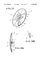
FIGS. 1 to 13 illustrate a first embodiment of the present invention wherein a wheel cover 1 is mounted to a wheel 3 of the automobiles e. g. a trunk, a bus, a car, and wherein a passenger car 2 is elected in this embodiment. The wheel cover 1 comprises a fixable side fixture 4, a movable side fixture 6 and a wheel cover body 7 in the shape of disc. The fixable side fixture 4 is fixably mounted at a place that the central part of the fixable side fixture 4 can be positioned to the center of the wheel 3. The side fixture 6 is rotatably mounted to the central part of the fixable side fixture 4 through a bearing 5. The wheel cover body 7 is mounted to the movable side fixture 6 while the wheel cover body 7 has a space between the wheel 3.
As illustrated in FIG. 3, the fixable side fixture 4 comprises a fixable side fixture body 10 and an axle insertable hole 11. wheel bolt insertable holes 9, 9 formed at both sides thereof receive wheel bolts 8, 8 inserted therein selectively of vis-a-vis even number of wheel bolts 8 are able to be fixed to the wheel 3. The fixable side fixture body 10 is formed roughly in the shape of a hat. The axle insertable hole 11 is formed in the central part of the fixable side fixture body 10.
As illustrated in FIG. 4, the movable side fixture 6 comprises a movable side fixture body 15, a ball bearing 5 as a bearing, an axle 17, a nut 18 and a weight 20. The movable side fixture body 15 is made of hard rubber or synthetic resin materials, forming a fitting piece 12 in the shape of a square in an upper part thereof and a weight supporting part 14 through a connection 13 in lower part thereof. The ball bearing 5 is insertably fixed to the nearly central part of the fitting piece 12 of the moval side fixture body 15. The axle 17 is fitably fixed to a rotating ring 5a of the ball bearing 5, inserted into an axle insertable hole 11 of the fixable side fixture 4 and formed thread ares 16 at an outer part thereof. The thread areas 16 of the axle 17 is secured in the nut 18, and the nut 18 fixes the axle 17 to the fixable side fixture 4. The weight 20 is fixed to a weight storage recess 19 formed in the weight supporting part 14 with adhesive.
Moreover, when the air valve projects rather than the surface of the wheel 3 of tire, the lower part of the movable side fixture 6 is planed at the place which is not to touch to to the air valve.
The wheel cover body 7 has a drawn design 21 which includes advertisement and/or publicity. As illustrated in FIGS. 5 to 7, the wheel cover body 7 is formed of metal or synthetic resin material and comprises a fitting part 22 and an air current guide part 24. The fitting part 22 is formed in the central part of the inner wall thereof and in the shape of channel a and section a of angle and can be removably inserted. The air current guide part 24 is a projection formed in the shape of a nose, having an air efflux 23 positioned to the backward during running.
In the above-mentioned wheel cover 1, as illustrates FIG. 8, the axle 17 of te movable side fixuture 6 is inserted into the axle insertable hole 11 of fixable side fixture 4, moreover, the nut 18 is screwed in the axle 17 and the movable side fixture 6 is mounted to the fixable side fixture 4. Secondary, as illustrates FIG. 9, the nut 25, 25, screwed in the wheel 3, is removed. After the wheel bolts 8, 8 are inserted into the wheel bolt insertable holes 9, 9 formed with th both sides of the fixable side fixture 4, the nuts 25, 25 are screwed in the wheel bolts 8, 8 and locked.
Additionnaly, as illustrates FIGS. 10 and 11, the fitting piece 12 of the movable side fixture 6 is set in the fitting part 22 of the wheel cover 7. Then, the connection 13 of the movable side fixture body 15 tranceforms with flexibility, and the connection 13 and weight supporting part 14 attach closely with the inner wall of the wheel cover body 7. In the above mentioned wheel cover 1 fixed to the wheel 3, the air current guide part 24 of the wheel cover body 7 as illustrates FIG. 12 can position to the backward of the passenger car 2 due to the weight 20 of the movable side fixture 6.
Under this situation, the fixable side fixture 4 as one with rotating the wheel 3 when the passenger car 2 moves, but the movable side fixture 6 and wheel cover body 7 are prevented to rotate due to the weight 20 and ball bearing 5 as a bearing.
Moreover, the air current happenes during running of the passenger car 2, but the air current with flowing to the surface of the wheel cover body 7 as illustrates FIG. 13 flows along the upper and lower parts of the air current guide part 24, and the rotating of wheel cover body 7 is prevented because the air inside the wheel cover body 7 is discharged with sucking from the air efflux 23.
The phenomenon shows that the rotating of the wheel cover body 7 is certainly prevented because it works greatly whenever the flow of an air current is fast, that is, the running speed of the passenger car 2 is faster than before.
Other embdiments of the pesent invention will now be described referring to FIGS. 14 to 71. Through the drawings of the embodiments, like components are denoted by like numerals as of the first embodiment and will not be further explained.
FIGS. 14 to 16 illustrate a second embodiment of the present invention which is distinguished from the first embodiment by a movable side fixture 6A formed as one of a fitting piece 26 for outer part of the connection 13 and a wheel cover body 7A formed an fitable hole 27 inserted the fitting piece 26 of the movable side fixture 6A when it is fixed. A wheel cover 1A with the movable side fixture 6A and wheel cover body 7A according to the second embodiment will provide the same effects as the first embodiment and the fitting piece 26 can prevent to remove the wheel cover body 7A and movable side fixture 6A in efficiency.
FIGS. 17 to 19 illustrate a third embodiment of the present invention which is distinguished from the first embodiment by a fixable side fixture 4A having three legs 28, 28, 28, capable with fixing to the passenger car 2 and is able to fix the wheel 3 with the uneven number of wheel bolts 8. A wheel cover 1B with the fixable side fixture 4B according to the third embodiment will provide the same effects as the first embodiment.
FIGS. 20 to 22 ilustrate a fourth embodiment of the present invention which is distinguished from the first embodiment by a fixable side fixture 4B comprises a bolt 29, a set board 31, a centering board 34 and the movable side fixture 5 mounted the ball bearing 5 as a bearing having the rotating ring 5a holdably fixed on top part of the bolt 29 of the fixable side fixture 4B with washers 35, 36 and a nut 37. The set board 31 in the shape of an oval or like a race track can be inserted at inner part greater than the place of an axle hole 30, inserted the bolt 29, positioned at the center of the wheel 3 and can set both sides of the center of the wheel 3. The centering board 32 is inserted into the axle hole 30, inserted the bolt 29 to the center part of the wheel 3 and conducts the centering. The spacer 33 and holding board 34 are inserted the bolt 29 in the center thereof. A wheel cover 1C with the fixable side fixture 4B and movable side fixture 6 according to the fourth embodiment will provided the same effects as the first embodiment and the wheel cover 1C can be set to the wheel 3 if the nut 25 of the wheel bolt 8 is removed.
FIGS. 23 to 25 illustrate a fifth embodiment of the pesent invention which is distinguished from the first embodiment by a wheel cover body 7B formed the air current guide part 24 is able to form the air efflux 23 to the end thereof. A wheel cover 1D with the wheel cover body 7B formed of the air current guide part 24 according to the fifth embodiment will provide the same effects as the first embodiment.
FIGS. 26 to 28 illustrate a sixth embodiment of the pesent invention which is distinguished from the second embodiment by a wheel cover 1E having a structure that the end of the fitable hole 27 can creep in a set gap 38 formed in the fitting piece 26, capable of preventing to move the wheel cover body 7A when the wheel cover body 7A move the direction of moving way under the condition that the fitting piece 12 of the movable side fixture 6A engages the fitting part 22 of te two wheel cover body 7A. The wheel cover 1E according to the sixth embodiment will provide the same effects as the second embodiment and part of edge of the fitable hole 27 creeps in the set gap 38 of the fitting piece 26 with the movable side fixture 6A if hte wheel cover body 7A removes due to be out of order so that the wheel cover body 7A can be prevented certainly to remove.
FIGS. 29 to 31 illustrate a seventh embodiment of the pesent invention which is distinguished from the first embodiment by a wheel cover body 7C formed a flange 39 bended inside part of outer edge thereofand a movable side fixture 6B formed an engagement 40 which can engage with the flange 39 of the wheel cover body 7C when the wheel cover body 7C is mounted to the lower part of the movable side fixture 15. A wheel cover 1F according to the seventh embodiment will provide the same effects as first embodiment and the moving to the direction of removing of the the wheel cover body 7C can be prevented because the engagement 40 of the movable side fixture 6B can engage with the flange 39 of the wheel cover body 7C.
FIGS. 32 to 34 illustrate an eighth embodiment of the pesent invention which is distinguished from the first embodiment by a wheel cover 1G comprises the fixable side fixture 4, a fitting piece 26A formed an insertable hole 42 for mounting of a lock 41, inserted in the fitable hole 27 formed the part of the nearly outer part of the wheel cover body 7D, to the weight supporting part 14 of the movable side side fixture 6C. The above-mentioned wheel cover 1G can prevent certainly to remove the wheel cover body 7D rom the movable side fixture 6C because the fitting piece 26A of the movable side fixture 6C can insert into the fitable hole 27 of the wheel cover body 7D.
Moreover, as illustartes FIG. 34, it can be certainly pevented tobe stolen the wheel cover body 7D because of the mounting the lock 41 to the insertable hole 42 of the fitting piece 26A.
FIGS. 35 to 37 illustrate a ninth embodiment of the pesent invention which is distinguished from the first embodiment by the mounting the movable side fixture 6 and the wheel cover body 7 with a multiplicity of, three of screws 43 is elected in this embodiment. A wheel cover 1H accoding to the ninth embodiment will provide the same effects as the first embodiment.
FIGS. 38 to 40 illustrate a tenth embodiment of the pesent invention which is distinguished from the ninth embodiment by a wheel cover body 7E having the weight 20 fixed with screw, adhesive, or weld at the lower part of the back face thereof. A wheel cover 1I with the wheel cover body 7E accoding to the tenth embodiment will provide the same effects as the ninth mbodiment.
FIGS. 41 to 43 illustrate an eleventh embodiment of the pesent invention which is distinguished from the seventh embodiment by a wheel cover body 7C formed the air effluxs 23, 23 at the backward thereof and reinforcement boards 44, 44 formed to the front and backward of the direction to the center of back of the wheel cover body 7C accoding to the eleventh embodiment will provide the same effects as the seventh embodiment.
FIGS. 44 to 46 illustrate a twelfth embodiment of the pesent invention which is distinguished from the first embodiment by the wheel cover body 7 mounted to the wheel bolt cover 45 covering only the part of the wheel bolt 8 of he wheel 3 through the ball bearing 5 as a bearing with the bolt 29 and nut 37, and the weight 20 fixed to the lower part of the back of the wheel cover body 7. A wheel cover 1K accroding to the twelfth embodiment will provide the same effects as the first embodiment.
Moreover, in this embodiment, the fixing structue of the wheel bolt cover 45 and wheel cover body 7 is available to use any structures rotatable mounted the wheel cover body 7.
FIGS. 47 to 49 illustrate a thirteenth embodiment of the pesent invention which is distinguished from the first embodiment by an engage piece 46 in the shape of a ring formed to the central part of back of a wheel cover body 7F covering to only part of the wheel bolt 8 of the wheel 3 and the ball bearing 5 as a bearing, formed the central part of the wheel 3, engageble fixed to a fitting part 47, moreover, the wheel cover body 7 mounted, inserting the bolt 29 as the movable side fixture into the rotating ring 5a of the ball bearing 5, and screwing the bolt 29 with a nut 37A formed a fitting gap 48 removing engaged the engage piece 46 in the shape of a ring at the outer part thereof. A wheel cover 1L according to the thirteenth embodiment will provide the same effects as the first embodiment.
FIGS. 50 to 53 illustrate a fourteenth embodiment of the present invention which is distinguished from the first embodiment by a nonreturn protection 49 can prevent to the backspin of the wheel cover body 7. A wheel cover 1M with the nonreturn protection 49 can prevent certainly to pivot the wheel cover body 7 when the automobile stops.
The nonreturn protection 49 comprises a ratchet gear 50 fixed to the wheel side fixture 4 and a set piece for nonreturn prevention 51, geared with the ratchet gear 50, pivoted by the movable side fixture 6.
Additionally, the nonreturn protection 49 provide the same effects if the bearing with rotating to one way, being on the market, is used instead of the ball bearing 5 as a bearing.
FIGS. 54 to 57 illustrate a fifteenth embodiment of the present invention which is distinguished from the first embodiment by the fact that a fitting part 22A, removably fitted the fitting piece 12 of the movable side fixture body 15 to the back of the wheel cover body 7, can be fixed to the upper and lower part set optionally up by a multiplicity of screws 52, that is, four pieces of screws 52. A wheel cover 1N mounted the fitting part 22A to the wheel cover body 7 with the multiplicity of screws can be used to mount to the wheel of right and left only the mounting direction of the fitting part 22A.
FIGS. 58 to 63 illustrate a sixteenth embodiment of the present invention which is distinguished from the fifteenth embodiment by set parts 54, 54 formed, with projecting in the shape of a chevron to the outer side, to both sides of nearly a bearing part 53 and a wheel cover 10 comprises a movable side fixture 6D formed an inlination for removing 55 at the top thereof, a fitting part 22B comprised with a first fitting member 60 and a second fitting member 62, a weight 20A pivotably mounted to the top of the movable side fixture 6D through a bearing 63 by a dead weight and a prevention piece for going 64. The first fitting member 60 is fixed with fanning out of the edge of opning thereof on the inner wall of the wheel cover body 7 with a multiplicity of screws 52, that is, four screws 52, 52, 52, 52 screwed in nuts 56, 56, 56, 56 fixed to the wheel cover body 7 in this embodiment and formed set parts 57, 57 which are able to set with set parts 54, 54 of the movable side fixture 6D in the inner side part of the opening thereof, having nut insertable holes 58, 58 and nut insertable holes 59, 59 in the shape of lengthy hole. The second fitting member 62 is positioned at an uuper part of the first fitting member 60 and formed set parts 61, 61 set with the outer of the bearing part 53 of the movable side fixture 6D, having the nut insertable holes 58, 58 and the nut insertable holes 59, 59 in the shape of lengthy hole, and used both as fitting members and a cover which can cover the circumference of the bearing part 53 of the movable side fixture 6D. The preventive piece for going 64 projects in the shape of a ring to the back side of te nearly outer part of the wheel cover body 7, and can prevent to come out with touching to the weight 20A when the wheel cover body 7 removes to the going direction and can pass through the inclination for removing 55 of the movable side fixture 6D when the wheel cover body 7 is removed with moving the weight 20 to the upper part thereof. A wheel cover 10 according to the sixteenth embodiment can prevent to go the wheel cover body 7 during use due to touch the wheel cover body 7 with the preventive piece for going 64 and weight 20A.
Moreover, th rotating of the wheel cover body 7 can be prevented with the effect to come to the end of rotating or pivotting due to the weight 20A pivotably mounted to the end of the movable side fixture 6D with a dead weight thereof.
Aditionaly, the wheel cover body 7 can remove to slide the inclination for removing 55 with the end of the movable side fitxture 6D on the preventive piece for going 64 because the weight pivots to the downward, removing to slide the wheel cover body 7 to the upward due to be positioned the end of te movable side fixture 6D to the upper aprt as illustrate FIG. 63.
FIGS. 64 to 66 illustrate a seventeenth embodiment of te present invention which is distinguished from the sixteenth embodiment by a preventive piece for going 64A molded with projection to the back to the nearly outer part of the wheel cover body 7. A wheel cover 1P with the wheel cover body 7 according to te seventeenth embodiment will povide the same effects as the sixteenth embodiment.
FIGS. 67 to 71 illustrate an eighteenth embodiment of te present invention which is distinguished from the sixteenth embodiment by a fan-shaped weight 20B pivotably mounted to the end of the movable side fixture 6, preventive pieces for going 65, 65 formed of inner wall of the wheel cove body 7, preventing the going with touching with the weight 20B when cover body 7 moves to the removing direction during use, and a fitting part 22B used to a guide piece 66 in the shape of tapering, can insert easily to the movable side fixture 6, having higher opening part side and lower inner part side. A wheel cover 1Q according to the eighteenth embodiment will provide the same effects as the sixteenth embodiment.
Moreover, in each of embodiments of the present invention, the use of the ball bearing as a bearing is explained, however, the present invention may use bearings which can rotatably support to the other bearings or axles.
Additionaly, in each of the embodiments, the oppsition board with flxibility to prevent to pivot the wheel cover body during stopping may be mounted to the wheel cover body, movable side fixture, fixable side fixture and/or the other part as to touch one part of the wheel. In this case, the wheel cover body can be prevented easily to pivot when the cart starts, with the opposition board mounted to the nearly center of axle rather than the part to apart from the center of axle.
As set forth above, the advantages of the present invention are as follows:
(1) A wheel cover comprising: a fixable side fixture fixably secured to the center of a wheel of a car, as to be able to position to the central part thereof; a movable side fixture pivoyably mounted to the central part of the fixable side fixture through a bearing; a wheel cover body in the shape of a disk mounted to the movable side fixture, having a space between the wheel; and a weight mounted to said movable side fixture or wheel cover body, in order to prevent to rotate the wheel cover body. Therefore, the wheel cover body is kept with stillness and stopping condition at fixed position by the weight, during running wheel cover body can be kept with the stillness condition because the movable side fixture.
Accordingly, people can see exactly the advertisement, publicity or design performed on the surface of wheel cover body because wheel cover body can be kept the stillness condition at fixed position during stopping and running, moreover, it can be prevented to cause the car accident with roll-up by a bus or a track because the wheel is covered by the wheel cover body in efficiency.
(2) As discussed above, it is easy to attract the design e. g. advertisement or publicity people attention and the effects of advertisement or publicity can be improve because the wheel cover body can pivotably swing a little due to the weight during stopping.
(3) As discussed above, the inspection of wheel bolt can be conducted easily after wheel cover body is removed easily when the bus is inspected at a commencement of work because it is easy to mount and remove the wheel cover body, and use it with simple structure.
(4) As discussed above, the air current guide part projecting in the shape of a nose can pass through the air currnt happened during running to the upper and lower part thereof because it is formed of the part positioned to the backward of te wheel cover body.
Therefore, the pivotting of the wheel cover body can be prevented.
(5) As discussed above, the claim (2) and (3) provide the same effects as above advantages of (1) to (4).
(6) As discussed above, the claim (4) to (8) provide the same effects as above advantages of (1) to (3).
Additional Remark
1. A wheel cover comprising: a fixable side fixture fixably mounted to the center of a wheel of a car, as to be able to position to the central part thereof; a movable side fixture rotatably mounted to the central part of the fixable side fixture through a bearing, formed of a fitting part in at least one side thereof and an inclination for removing on the top thereof; a weight pivotably mounted, with dead weight itself, to the top of the movable side fixture through the bearing; a wheel cover body in the shape of a disk mounted to the inserted movable side fixture with having a space between the wheel, mounted a fitting member with the fitting part and a fitted fitting part into an inside wall thereof; and a preventive piece for going, in the shape of a ring, mold with projection to the back to the the wheel cover body, and can prevent to come out with touching to the weight when the wheel cover body removes to the going direction, can pass through the inclination for removing of the movable side fixture when the wheel cover body is removed with moving the weight to the upper part thereof.
2. A wheel cover comprising: a fixable side fixture fixably mounted to the center of a wheel of a car, as to be able to position to the central part thereof; a movable side fixture pivotably mounted to the central part of the fixable side fixture through a bearing; a weight pivotably mounted to the top of the movable side fixture through the bearing; a wheel cover body in the shape of a disk removably fitted, having a space between the wheel, to the movable side fixture; and a preventive piece for going, in the shape of a ring, mold with projection to the back to the the wheel cover body, and can prevent to come out with touching to the weight when the wheel cover body removes to the going direction, can pass through the inclination for removing of the movable side fixture when the wheel cover body is removed with moving the weight to the upper part thereof.
Claims (15)
1. A wheel cover comprising:
a mounting member fixedly mountable to a center of a wheel of a vehicle;
a bearing centrally mounted to said mounting member;
a movable member pivotably mounted to the mounting member through the bearing;
a wheel cover body in the shape of a disk receivable to the movable member, said wheel cover body including structure carried centrally on a side thereof facing inwardly of the wheel for fastenably engaging corresponding structure carried on said movable member in a manner allowing removable connection of the wheel cover body to the movable member while preventing relative rotational movement therebetween, and when so received, a space being defined between the wheel and the wheel cover to permit concentric rotation of said wheel cover body and said movable member together relative said wheel about said bearing, said wheel cover body including structure cooperative with receiving structure carried on said movable member for permitting slidable reception of said wheel cover body to said movable member along a receiving direction orthogonal to the rotational axis of the wheel; and
a weight mounted to said movable member for preventing rotation of the movable member and the wheel cover body by operation of gravity thereon as the wheel of the vehicle is rotated.
2. A wheel cover according to claim 1, wherein the weight is provided as a weighted portion carried on said movable member in a position radially outward from a point of mounting to said bearing in order to prevent rotation of the wheel cover body when received to said movable member.
3. A wheel cover comprising:
a mounting member fixedly mountable to a center of a wheel of a vehicle;
a bearing centrally mounted to said mounting member;
a movable member pivotably mounted to the mounting member through the bearing;
a wheel cover body in the shape of a disk receivable to the movable member, said wheel cover body including structure carried centrally on a side thereof facing inwardly of the wheel for fastenably engaging corresponding structure carried on said movable member in a manner allowing removable connection of the wheel cover body to the movable member while preventing relative rotational movement therebetween, and when so received, a space being defined between the wheel and the wheel cover to permit concentric rotation of said wheel cover body and said movable member together relative said wheel about said bearing;
a weight mounted to said movable member for preventing rotation of the movable member and the wheel cover body by operation of gravity thereon as the wheel of the vehicle is rotated; and
the wheel cover body including an air current guide part formed generally in the shape of a nose, and positioned on said wheel cover body radially outward of a center thereof, said air current guide part presenting structure which is generally bilaterally symmetric about an air-current conduction axis which extends radially outward of the center of the wheel cover body, said air current guide being arranged on said wheel cover body such that it is oriented rearward of the vehicle when the wheel cover body is received to the movable member and in a weighted orientation, whereby an air current created when the vehicle is moving is codirectionally conducted along said air-current conduction axis in a manner providing resistance against rotation of said wheel cover body.
4. A wheel cover, comprising:
a mounting bracket mountable on a wheel of a vehicle in fixed engagement therewith, said mounting bracket including a structural configuration attachable to a central region of the wheel;
a movable member pivotably mounted to the mounting bracket for permitting rotation of the movable member relative to the wheel about a rotational axis of the wheel;
a wheel cover body receivable to the movable member in a manner inhibiting relative rotational movement therebetween, there being sufficient clearance between the wheel cover body and the wheel when the wheel cover body is received thereto to permit concentric rotation of said wheel cover body relative said wheel about said rotational axis; and
a weight mounted to a one of said movable member and said wheel cover body and positioned in a manner creating a center of gravity located radially outward of a center of the wheel cover body such that the wheel cover body tends to move to a position in which a straight locus connecting the center of the wheel cover body and the center of gravity extends vertically, whereby a desired rotational orientation of the wheel cover body is generally maintained while the wheel is stationary and during rotation thereof by operation of gravity.
5. A wheel cover according to claim 4, further comprising a bearing for pivotably mounting said movable member to said mounting bracket.
6. A wheel cover according to claim 4, wherein the weight includes a weighted portion carried on said movable member in a position radially outward from a point of mounting to said bearing in order to inertially inhibit rotation of the wheel cover body when received to said movable member.
7. A wheel cover, comprising:
a mounting bracket mountable on a wheel of a vehicle in fixed engagement therewith;
movable member pivotably mounted to the mounting bracket for permitting rotation of the movable member relative to the wheel about a rotational axis of the wheel;
a wheel cover body receivable to the movable member in a manner inhibiting relative rotational movement therebetween, there being sufficient clearance between the wheel cover body and the wheel when the wheel cover body is received thereto to permit concentric rotation of said wheel cover body relative said wheel about said rotational axis;
a weight mounted to a one of said movable member and said wheel cover body and positioned in a manner creating a center of gravity located radially outward of a center of the wheel cover body such that the wheel cover body tends to move to a position in which a straight locus connecting the center of the wheel cover body and the center of gravity extends vertically, whereby a desired rotational orientation of the wheel cover body is generally maintained while the wheel is stationary and during rotation thereof by operation of gravity; and
the wheel cover body including an air current guide positioned on said wheel cover body radially outward of a center thereof, said air current guide presenting structure for conducting air flowing therepast codirectionally with an air-current conduction axis of said air current guide, said air-current conduction axis being positioned orthogonally with said straight locus, whereby an air current created when the vehicle is moving is codirectionally conducted along said air-current conduction axis in a manner providing additional resistance against rotation of said wheel cover body.
8. A wheel cover according to claim 7, wherein said air current guide extends radially outward of the center of the wheel cover body, said air current guide being arranged on said wheel cover body such that it is oriented rearward of the vehicle when the wheel cover body is received to the movable member.
9. A wheel cover according to claim 7, wherein said air current guide is generally bilaterally symmetric about said air-current conduction axis.
10. A wheel cover according to claim 4, wherein said wheel cover body including structure cooperative with receiving structure carried on said movable member for permitting slidable reception of said wheel cover body to said movable member along a receiving direction orthogonal to the rotational axis of the wheel.
11. A wheel cover according to claim 10, wherein a portion of said movable member located radially outward of said receiving structure protrudes at least partially through said wheel cover body.
12. A wheel cover according to claim 11, wherein said portion of said movable member includes structure engageble with said wheel cover body for safeguarding against unintentional detachment of said wheel cover said movable member.
13. A wheel cover, comprising:
a mounting bracket mountable on a wheel of a vehicle in fixed engagement therewith;
a movable member pivotably mounted to the mounting bracket for permitting rotation of the movable member relative to the wheel about a rotational axis of the wheel;
a wheel cover body receivable to the movable member in a manner inhibiting relative rotational movement therebetween, there being sufficient clearance between the wheel cover body and the wheel when the wheel cover body is received thereto to permit concentric rotation of said wheel cover body relative said wheel about said rotational axis, said wheel cover body including structure cooperative with receiving structure carried on said movable member for permitting slidable reception of said wheel cover body to said movable member along a receiving direction orthogonal to said rotational axis of the wheel; and
a weight mounted to a one of said movable member and said wheel cover body and positioned in a manner creating a center of gravity located radially outward of a center of the wheel cover body such that the wheel cover body tends to move to a position in which a straight locus connecting the center of the wheel cover body and the center of gravity extends vertically, whereby a desired rotational orientation of the wheel cover body is generally maintained while the wheel is stationary and during rotation thereof by operation of gravity.
14. A wheel cover according to claim 10, wherein said receiving direction extends vertically.
15. A wheel cover according to claim 13, wherein the wheel cover body includes an air current guide positioned on said wheel cover body radially outward of a center thereof, said air current guide presenting structure for conducting air flowing therepast codirectionally with an air-current conduction axis of said air current guide, said air current axis being positioned orthogonally with said straight locus, whereby an air current created when the vehicle is moving is codirectionally conducted along said air-current conduction axis in a manner providing additional resistance against rotation of said wheel cover body.
Applications Claiming Priority (4)
| Application Number | Priority Date | Filing Date | Title |
|---|---|---|---|
| JP30345196 | 1996-10-09 | ||
| JP8-303451 | 1996-10-09 | ||
| JP10250997 | 1997-04-04 | ||
| JP9-102509 | 1997-04-04 |
Publications (1)
| Publication Number | Publication Date |
|---|---|
| US6120104A true US6120104A (en) | 2000-09-19 |
Family
ID=26443228
Family Applications (1)
| Application Number | Title | Priority Date | Filing Date |
|---|---|---|---|
| US08/944,893 Expired - Fee Related US6120104A (en) | 1996-10-09 | 1997-10-03 | Wheel cover |
Country Status (1)
| Country | Link |
|---|---|
| US (1) | US6120104A (en) |
Cited By (53)
| Publication number | Priority date | Publication date | Assignee | Title |
|---|---|---|---|---|
| WO2002014084A1 (en) * | 2000-08-11 | 2002-02-21 | The Rhegos Group, Llc | Wheel spinner assembly independently rotatable relative to a corresponding wheel |
| US6363642B1 (en) * | 2000-03-16 | 2002-04-02 | Throttle Corporation | Apparatus and method for simulating the appearance of wheels |
| US6443529B1 (en) * | 2000-08-17 | 2002-09-03 | Curtis A. Williams | Assembly with a non-rotatable wheel cover disc |
| US6536848B1 (en) | 2002-03-22 | 2003-03-25 | International Adcaps, Inc. | Non-rotating display wheel cover |
| US6568110B2 (en) * | 2001-04-20 | 2003-05-27 | Dong In Tec Co., Ltd. | Nonrotating billboard of rotation body |
| US6637830B1 (en) | 2002-06-17 | 2003-10-28 | Walter Burgess | Spinable wheel cover |
| US6655061B1 (en) * | 2002-07-24 | 2003-12-02 | Lawrence D. Good | One way free spinning hubcap |
| US20040053546A1 (en) * | 2002-08-13 | 2004-03-18 | Yoshimoto Matsuda | Small watercraft |
| US20040100141A1 (en) * | 2000-10-17 | 2004-05-27 | Bernd Litzka | Wheel cover for covering the rim of a vehicle wheel |
| US20040183359A1 (en) * | 2003-03-18 | 2004-09-23 | David Fowlkes | Wheel spinner assembly independently rotatable relative to a corresponding wheel |
| US20050035651A1 (en) * | 2003-08-15 | 2005-02-17 | Leslie Hsiao | Non-rotating display wheel cover |
| US6857709B1 (en) * | 2003-12-16 | 2005-02-22 | Aai Technology Inc. | Non-rotating wheel cover |
| US20050062336A1 (en) * | 2003-09-18 | 2005-03-24 | Leslie Hsiao | Non-rotating display wheel cover |
| US20050067880A1 (en) * | 2003-09-26 | 2005-03-31 | Buhler Kirk A. | Free spinning vehicle wheel cover |
| US20050093362A1 (en) * | 2003-10-31 | 2005-05-05 | Jorge Alicea | Oscillating wheel accessory |
| US20050146203A1 (en) * | 2004-01-06 | 2005-07-07 | Rocky Lin | Wheel frame re-equipping mechanism with a rotatable blade |
| US20050146202A1 (en) * | 2004-01-06 | 2005-07-07 | Rocky Lin | Wheel frame re-equipping mechanism with a rotatable blade |
| US20050194833A1 (en) * | 2004-03-08 | 2005-09-08 | Strzelczyk Justin C. | Spinner hub assembly |
| US20050206123A1 (en) * | 2004-02-25 | 2005-09-22 | Young Scott J | Non-rotating bicycle wheel display disk |
| EP1591276A2 (en) | 2004-04-30 | 2005-11-02 | Maier, S. Coop. | Badge Holder system for rotating support part |
| US6964454B1 (en) | 2004-09-16 | 2005-11-15 | Miansian James K | Wheel with center spinner |
| US7014273B1 (en) * | 2004-03-22 | 2006-03-21 | Billy Yang | Spoked wheel spinner with non-rotating cap |
| US20060152068A1 (en) * | 2002-07-09 | 2006-07-13 | Richard Steven Lock Adcap Media Ltd. | Motor vehicle accessory |
| US20060181138A1 (en) * | 2004-03-04 | 2006-08-17 | Courtney Eric S | Wheel design |
| US20060192422A1 (en) * | 2005-02-25 | 2006-08-31 | Jeffrey Goodman | Wheel cover |
| US20060208559A1 (en) * | 2005-03-17 | 2006-09-21 | Morris Bruce E | Wheel ornament assembly as constantly vertical for rotationally independant wheel spinner |
| US20060255652A1 (en) * | 2005-02-25 | 2006-11-16 | Robert Kaufman | Vehicle wheel display assembly |
| US20060277806A1 (en) * | 2005-02-25 | 2006-12-14 | Dovale Anthony J Jr | Vehicle Wheel Display Assembly |
| US20070046096A1 (en) * | 2005-08-30 | 2007-03-01 | James Marriott | Powered spinning hubcap |
| US20070102993A1 (en) * | 2005-11-09 | 2007-05-10 | Kagen Alan M | Rotatable hubcap assembly with audio generating device |
| US20070167273A1 (en) * | 2006-01-13 | 2007-07-19 | Nissan Technical Center North America, Inc. | Reverse spinning wheel cover |
| US20070200421A1 (en) * | 2006-02-24 | 2007-08-30 | Dovale Anthony J Jr | Wheel cover |
| US20070199220A1 (en) * | 2005-09-21 | 2007-08-30 | Dovale Anthony J Jr | Vehicle wheel display assembly |
| US20080036285A1 (en) * | 2006-08-14 | 2008-02-14 | Bouncing Brain Productions Subsidiary 11, Llc | Rim assembly with oscillator |
| US20080106140A1 (en) * | 2006-11-06 | 2008-05-08 | Andres Velez | Display Apparatus For Wheel Hub |
| US20080272643A1 (en) * | 2004-02-25 | 2008-11-06 | Scott James Young | Non-rotating bicycle wheel display disk |
| US8814253B1 (en) | 2011-04-21 | 2014-08-26 | Flowbelow, LLC | Aerodynamic quarter fender assembly and construction method |
| US20140265533A1 (en) * | 2013-03-15 | 2014-09-18 | RealWheels Corporation | Wheel Cover Assembly and Method of Mounting |
| US9027983B2 (en) | 2012-11-01 | 2015-05-12 | FlowBelow Aero, Inc. | Aerodynamic system and adjustable fairings |
| US9327550B2 (en) | 2011-07-12 | 2016-05-03 | FlowBelow Aero, Inc. | Aerodynamic wheel covers and mounting assemblies |
| FR3044591A1 (en) * | 2015-12-02 | 2017-06-09 | Renault Sas | AERODYNAMIC RIM TRIM |
| US9902195B2 (en) * | 2016-03-29 | 2018-02-27 | Juan Carlos Castro-Villanueva | Non-rotating center cap |
| USD867966S1 (en) * | 2017-08-11 | 2019-11-26 | Tony Michael Barton | Mirrored hubcap assembly |
| US20200114681A1 (en) * | 2018-10-11 | 2020-04-16 | Mclaren Automotive Limited | Wheel cover |
| US10654529B2 (en) | 2017-06-24 | 2020-05-19 | FlowBelow Aero, Inc. | Aerodynamic systems and fairings with fairing caps |
| US10703132B2 (en) | 2017-09-22 | 2020-07-07 | Consolidated Metco, Inc. | Wheel cover |
| US10882571B2 (en) | 2017-07-30 | 2021-01-05 | FlowBelow Aero, Inc. | Rotatable aerodynamic fairing system |
| US11072377B2 (en) | 2018-09-04 | 2021-07-27 | Lund, Inc. | Removable fairing |
| GB2591758A (en) * | 2020-02-05 | 2021-08-11 | Daimler Ag | Wheel cover device for vehicle |
| US11352073B2 (en) | 2017-07-12 | 2022-06-07 | FlowBelow Aero, Inc. | Aerodynamic toolbox assembly |
| US11667151B2 (en) | 2019-03-01 | 2023-06-06 | Consolidated Metco, Inc. | Wheel cover |
| US11767064B2 (en) | 2021-01-12 | 2023-09-26 | FlowBelow Aero, Inc. | Spring-biased mud flap hanger with improved pivoting motion guidance |
| US11932060B2 (en) | 2016-11-04 | 2024-03-19 | FlowBelow Aero, Inc. | Chassis mounted energy extraction and delivery system |
Citations (30)
| Publication number | Priority date | Publication date | Assignee | Title |
|---|---|---|---|---|
| US1432274A (en) * | 1922-05-18 | 1922-10-17 | Braucher Edward Franklin | Advertising disk for automobile wheels |
| US1478475A (en) * | 1923-04-18 | 1923-12-25 | Jago Alfred Charles | Advertising device for road and other vehicles |
| US1665437A (en) * | 1925-03-16 | 1928-04-10 | William N Booth | Vehicle wheel |
| US2130220A (en) * | 1937-10-08 | 1938-09-13 | George D Ball | Nonrotatable hub cap |
| US2169237A (en) * | 1938-01-04 | 1939-08-15 | Gasco Pete | Stationary ornament for wheel hub caps |
| US2548070A (en) * | 1948-11-22 | 1951-04-10 | Arthur M Ryan | Advertising display device |
| US2631204A (en) * | 1949-04-01 | 1953-03-10 | Willys Overland Motors Inc | Switch actuating means |
| US2707131A (en) * | 1953-01-07 | 1955-04-26 | Sundberg & Ferar | Wheel ornament holding structure |
| US2754154A (en) * | 1954-11-01 | 1956-07-10 | Solow Benjamin | Stationary hub cap cover |
| US2759282A (en) * | 1953-01-29 | 1956-08-21 | Lecourt Valere | Display disc attachment device |
| US2762469A (en) * | 1953-09-25 | 1956-09-11 | Lyon George Albert | Wheel cover |
| CA541032A (en) * | 1957-05-21 | A. Lyon George | Wheel structure | |
| US2869262A (en) * | 1957-06-03 | 1959-01-20 | Charles D Lucas | Wheel-supported advertizing signs |
| US2997344A (en) * | 1959-12-28 | 1961-08-22 | Levi B Whiteman | Wheel cover |
| US3005906A (en) * | 1959-08-19 | 1961-10-24 | Jr Hardie T Butler | Hub cap ornament |
| US3219391A (en) * | 1964-03-27 | 1965-11-23 | Gustave Miller | Revolving wheel disc cover |
| US3722958A (en) * | 1970-12-23 | 1973-03-27 | W Marshall | Rotative wheel covers, and the like |
| CA925539A (en) * | 1971-02-18 | 1973-05-01 | Titze Ronald | Wheel and tire cover |
| US3918186A (en) * | 1974-05-28 | 1975-11-11 | Frank H Gray | Wheel mounted display device |
| US4040582A (en) * | 1975-09-09 | 1977-08-09 | Krauss Ronald C | Wind power accessory for a vehicle wheel |
| US4678239A (en) * | 1984-09-27 | 1987-07-07 | Yutaka Matsushita | Free wheel cap |
| US4707035A (en) * | 1984-04-14 | 1987-11-17 | Marui Industry Co., Ltd. | Synthetic resin vehicle wheel cover |
| EP0330534A2 (en) * | 1988-02-02 | 1989-08-30 | Seung Moon Park | Stationary billboard on the hub cap |
| US4981329A (en) * | 1989-11-02 | 1991-01-01 | Koch Paul E | Non moving wheel cover |
| US5190354A (en) * | 1991-05-13 | 1993-03-02 | Serge Levy | Vehicle wheel cover |
| US5263770A (en) * | 1991-11-07 | 1993-11-23 | Goudey Robert B | Vehicle wheel cover |
| US5490342A (en) * | 1994-07-13 | 1996-02-13 | Rutterman; Michael J. | Non-rotating wheel cover |
| US5588715A (en) * | 1994-06-20 | 1996-12-31 | Harlen; Charles D. | Non-rotating wheel cover assembly |
| US5659989A (en) * | 1994-07-13 | 1997-08-26 | Hsiao; Leslie | Wheel cover |
| US5957542A (en) * | 1997-05-30 | 1999-09-28 | Boothe; Ralph T. | Theft-proof non-rotating wheel cover with replaceable ornament |
-
1997
- 1997-10-03 US US08/944,893 patent/US6120104A/en not_active Expired - Fee Related
Patent Citations (31)
| Publication number | Priority date | Publication date | Assignee | Title |
|---|---|---|---|---|
| CA541032A (en) * | 1957-05-21 | A. Lyon George | Wheel structure | |
| US1432274A (en) * | 1922-05-18 | 1922-10-17 | Braucher Edward Franklin | Advertising disk for automobile wheels |
| US1478475A (en) * | 1923-04-18 | 1923-12-25 | Jago Alfred Charles | Advertising device for road and other vehicles |
| US1665437A (en) * | 1925-03-16 | 1928-04-10 | William N Booth | Vehicle wheel |
| US2130220A (en) * | 1937-10-08 | 1938-09-13 | George D Ball | Nonrotatable hub cap |
| US2169237A (en) * | 1938-01-04 | 1939-08-15 | Gasco Pete | Stationary ornament for wheel hub caps |
| US2548070A (en) * | 1948-11-22 | 1951-04-10 | Arthur M Ryan | Advertising display device |
| US2631204A (en) * | 1949-04-01 | 1953-03-10 | Willys Overland Motors Inc | Switch actuating means |
| US2707131A (en) * | 1953-01-07 | 1955-04-26 | Sundberg & Ferar | Wheel ornament holding structure |
| US2759282A (en) * | 1953-01-29 | 1956-08-21 | Lecourt Valere | Display disc attachment device |
| US2762469A (en) * | 1953-09-25 | 1956-09-11 | Lyon George Albert | Wheel cover |
| US2754154A (en) * | 1954-11-01 | 1956-07-10 | Solow Benjamin | Stationary hub cap cover |
| US2869262A (en) * | 1957-06-03 | 1959-01-20 | Charles D Lucas | Wheel-supported advertizing signs |
| US3005906A (en) * | 1959-08-19 | 1961-10-24 | Jr Hardie T Butler | Hub cap ornament |
| US2997344A (en) * | 1959-12-28 | 1961-08-22 | Levi B Whiteman | Wheel cover |
| US3219391A (en) * | 1964-03-27 | 1965-11-23 | Gustave Miller | Revolving wheel disc cover |
| US3722958A (en) * | 1970-12-23 | 1973-03-27 | W Marshall | Rotative wheel covers, and the like |
| CA925539A (en) * | 1971-02-18 | 1973-05-01 | Titze Ronald | Wheel and tire cover |
| US3918186A (en) * | 1974-05-28 | 1975-11-11 | Frank H Gray | Wheel mounted display device |
| US4040582A (en) * | 1975-09-09 | 1977-08-09 | Krauss Ronald C | Wind power accessory for a vehicle wheel |
| US4707035A (en) * | 1984-04-14 | 1987-11-17 | Marui Industry Co., Ltd. | Synthetic resin vehicle wheel cover |
| US4678239A (en) * | 1984-09-27 | 1987-07-07 | Yutaka Matsushita | Free wheel cap |
| EP0330534A2 (en) * | 1988-02-02 | 1989-08-30 | Seung Moon Park | Stationary billboard on the hub cap |
| US4929030A (en) * | 1988-02-02 | 1990-05-29 | Park Seung M | Stationary member on automotive hub cap |
| US4981329A (en) * | 1989-11-02 | 1991-01-01 | Koch Paul E | Non moving wheel cover |
| US5190354A (en) * | 1991-05-13 | 1993-03-02 | Serge Levy | Vehicle wheel cover |
| US5263770A (en) * | 1991-11-07 | 1993-11-23 | Goudey Robert B | Vehicle wheel cover |
| US5588715A (en) * | 1994-06-20 | 1996-12-31 | Harlen; Charles D. | Non-rotating wheel cover assembly |
| US5490342A (en) * | 1994-07-13 | 1996-02-13 | Rutterman; Michael J. | Non-rotating wheel cover |
| US5659989A (en) * | 1994-07-13 | 1997-08-26 | Hsiao; Leslie | Wheel cover |
| US5957542A (en) * | 1997-05-30 | 1999-09-28 | Boothe; Ralph T. | Theft-proof non-rotating wheel cover with replaceable ornament |
Cited By (80)
| Publication number | Priority date | Publication date | Assignee | Title |
|---|---|---|---|---|
| US6363642B1 (en) * | 2000-03-16 | 2002-04-02 | Throttle Corporation | Apparatus and method for simulating the appearance of wheels |
| WO2002014084A1 (en) * | 2000-08-11 | 2002-02-21 | The Rhegos Group, Llc | Wheel spinner assembly independently rotatable relative to a corresponding wheel |
| US6554370B2 (en) | 2000-08-11 | 2003-04-29 | David Fowlkes | Wheel spinner assembly independently rotatable relative to a corresponding wheel |
| US6443529B1 (en) * | 2000-08-17 | 2002-09-03 | Curtis A. Williams | Assembly with a non-rotatable wheel cover disc |
| US6983998B2 (en) * | 2000-10-17 | 2006-01-10 | Bernd Litzka | Wheel cover for covering the rim of a vehicle wheel |
| US20040100141A1 (en) * | 2000-10-17 | 2004-05-27 | Bernd Litzka | Wheel cover for covering the rim of a vehicle wheel |
| US6568110B2 (en) * | 2001-04-20 | 2003-05-27 | Dong In Tec Co., Ltd. | Nonrotating billboard of rotation body |
| US6536848B1 (en) | 2002-03-22 | 2003-03-25 | International Adcaps, Inc. | Non-rotating display wheel cover |
| EP1346851A2 (en) | 2002-03-22 | 2003-09-24 | Hsiao, Leslie C. | Non-rotating display wheel cover |
| US6637830B1 (en) | 2002-06-17 | 2003-10-28 | Walter Burgess | Spinable wheel cover |
| US20060152068A1 (en) * | 2002-07-09 | 2006-07-13 | Richard Steven Lock Adcap Media Ltd. | Motor vehicle accessory |
| US6655061B1 (en) * | 2002-07-24 | 2003-12-02 | Lawrence D. Good | One way free spinning hubcap |
| US20040053546A1 (en) * | 2002-08-13 | 2004-03-18 | Yoshimoto Matsuda | Small watercraft |
| US20040183359A1 (en) * | 2003-03-18 | 2004-09-23 | David Fowlkes | Wheel spinner assembly independently rotatable relative to a corresponding wheel |
| US20050035651A1 (en) * | 2003-08-15 | 2005-02-17 | Leslie Hsiao | Non-rotating display wheel cover |
| US20050062336A1 (en) * | 2003-09-18 | 2005-03-24 | Leslie Hsiao | Non-rotating display wheel cover |
| US20050067880A1 (en) * | 2003-09-26 | 2005-03-31 | Buhler Kirk A. | Free spinning vehicle wheel cover |
| US20050093362A1 (en) * | 2003-10-31 | 2005-05-05 | Jorge Alicea | Oscillating wheel accessory |
| US6857709B1 (en) * | 2003-12-16 | 2005-02-22 | Aai Technology Inc. | Non-rotating wheel cover |
| US20050146202A1 (en) * | 2004-01-06 | 2005-07-07 | Rocky Lin | Wheel frame re-equipping mechanism with a rotatable blade |
| US20050146203A1 (en) * | 2004-01-06 | 2005-07-07 | Rocky Lin | Wheel frame re-equipping mechanism with a rotatable blade |
| US7347439B2 (en) | 2004-02-25 | 2008-03-25 | Scott James Young | Non-rotating bicycle wheel display disk |
| US20050206123A1 (en) * | 2004-02-25 | 2005-09-22 | Young Scott J | Non-rotating bicycle wheel display disk |
| US20080272643A1 (en) * | 2004-02-25 | 2008-11-06 | Scott James Young | Non-rotating bicycle wheel display disk |
| US7775540B2 (en) | 2004-02-25 | 2010-08-17 | Scott James Young | Non-rotating bicycle wheel display disk |
| US7347502B2 (en) | 2004-03-04 | 2008-03-25 | Eric Scott Courtney | Wheel design |
| US20060181138A1 (en) * | 2004-03-04 | 2006-08-17 | Courtney Eric S | Wheel design |
| US7121631B2 (en) | 2004-03-08 | 2006-10-17 | Strzelczyk Justin C | Spinner hub assembly |
| US20050194833A1 (en) * | 2004-03-08 | 2005-09-08 | Strzelczyk Justin C. | Spinner hub assembly |
| US7014273B1 (en) * | 2004-03-22 | 2006-03-21 | Billy Yang | Spoked wheel spinner with non-rotating cap |
| EP1591276A2 (en) | 2004-04-30 | 2005-11-02 | Maier, S. Coop. | Badge Holder system for rotating support part |
| US6964454B1 (en) | 2004-09-16 | 2005-11-15 | Miansian James K | Wheel with center spinner |
| US20060255652A1 (en) * | 2005-02-25 | 2006-11-16 | Robert Kaufman | Vehicle wheel display assembly |
| US20060277806A1 (en) * | 2005-02-25 | 2006-12-14 | Dovale Anthony J Jr | Vehicle Wheel Display Assembly |
| US7472966B2 (en) | 2005-02-25 | 2009-01-06 | Static Media Group, Llc | Wheel cover assembly having stationary display and base member for mounting to a wheel |
| US20060192422A1 (en) * | 2005-02-25 | 2006-08-31 | Jeffrey Goodman | Wheel cover |
| US20060208559A1 (en) * | 2005-03-17 | 2006-09-21 | Morris Bruce E | Wheel ornament assembly as constantly vertical for rotationally independant wheel spinner |
| US7354113B2 (en) | 2005-08-30 | 2008-04-08 | James Marriott | Powered spinning hubcap |
| US20070046096A1 (en) * | 2005-08-30 | 2007-03-01 | James Marriott | Powered spinning hubcap |
| US20070199220A1 (en) * | 2005-09-21 | 2007-08-30 | Dovale Anthony J Jr | Vehicle wheel display assembly |
| US7472967B2 (en) | 2005-09-21 | 2009-01-06 | Static Media Group, Llc | Vehicle wheel display assembly |
| US20070102993A1 (en) * | 2005-11-09 | 2007-05-10 | Kagen Alan M | Rotatable hubcap assembly with audio generating device |
| US20070167273A1 (en) * | 2006-01-13 | 2007-07-19 | Nissan Technical Center North America, Inc. | Reverse spinning wheel cover |
| US20070200421A1 (en) * | 2006-02-24 | 2007-08-30 | Dovale Anthony J Jr | Wheel cover |
| US20080036285A1 (en) * | 2006-08-14 | 2008-02-14 | Bouncing Brain Productions Subsidiary 11, Llc | Rim assembly with oscillator |
| US7661766B2 (en) * | 2006-08-14 | 2010-02-16 | Davis Jon R | Rim assembly with oscillator |
| US20080106140A1 (en) * | 2006-11-06 | 2008-05-08 | Andres Velez | Display Apparatus For Wheel Hub |
| US8814253B1 (en) | 2011-04-21 | 2014-08-26 | Flowbelow, LLC | Aerodynamic quarter fender assembly and construction method |
| US11220132B2 (en) | 2011-07-12 | 2022-01-11 | FlowBelow Aero, Inc. | Aerodynamic wheel covers and mounting assemblies |
| US9327550B2 (en) | 2011-07-12 | 2016-05-03 | FlowBelow Aero, Inc. | Aerodynamic wheel covers and mounting assemblies |
| US10343450B2 (en) | 2011-07-12 | 2019-07-09 | FlowBelow Aero, Inc. | Aerodynamic wheel covers and mounting assemblies |
| US9027983B2 (en) | 2012-11-01 | 2015-05-12 | FlowBelow Aero, Inc. | Aerodynamic system and adjustable fairings |
| US11667338B2 (en) | 2012-11-01 | 2023-06-06 | FlowBelow Aero, Inc. | Aerodynamic system and adjustable fairings |
| US10252755B2 (en) | 2012-11-01 | 2019-04-09 | FlowBelow Aero, Inc. | Aerodynamic system and adjustable fairings |
| US10710649B2 (en) | 2012-11-01 | 2020-07-14 | FlowBelow Aero, Inc. | Aerodynamic system and adjustable fairings |
| US9663157B2 (en) | 2012-11-01 | 2017-05-30 | FlowBelow Aero, Inc. | Aerodynamic system and adjustable fairings |
| US10293872B2 (en) | 2012-11-01 | 2019-05-21 | FlowBelow Aero, Inc. | Aerodynamic system and adjustable fairings |
| US20140265533A1 (en) * | 2013-03-15 | 2014-09-18 | RealWheels Corporation | Wheel Cover Assembly and Method of Mounting |
| US20160193870A1 (en) * | 2013-03-15 | 2016-07-07 | RealWheels Corporation | Wheel Cover Assembly and Method of Mounting |
| US9365074B2 (en) * | 2013-03-15 | 2016-06-14 | RealWheels Corporation | Wheel cover assembly and method of mounting |
| US9511624B2 (en) * | 2013-03-15 | 2016-12-06 | RealWheels Corporation | Wheel cover assembly and method of mounting |
| FR3044591A1 (en) * | 2015-12-02 | 2017-06-09 | Renault Sas | AERODYNAMIC RIM TRIM |
| US9902195B2 (en) * | 2016-03-29 | 2018-02-27 | Juan Carlos Castro-Villanueva | Non-rotating center cap |
| US11932060B2 (en) | 2016-11-04 | 2024-03-19 | FlowBelow Aero, Inc. | Chassis mounted energy extraction and delivery system |
| US10654529B2 (en) | 2017-06-24 | 2020-05-19 | FlowBelow Aero, Inc. | Aerodynamic systems and fairings with fairing caps |
| US11254373B2 (en) | 2017-06-24 | 2022-02-22 | FlowBelow Aero, Inc. | Aerodynamic systems and fairings with fairing caps |
| US11352073B2 (en) | 2017-07-12 | 2022-06-07 | FlowBelow Aero, Inc. | Aerodynamic toolbox assembly |
| US10882571B2 (en) | 2017-07-30 | 2021-01-05 | FlowBelow Aero, Inc. | Rotatable aerodynamic fairing system |
| US11273877B2 (en) | 2017-07-30 | 2022-03-15 | FlowBelow Aero, Inc. | Rotatable aerodynamic fairing system |
| US11492053B2 (en) | 2017-07-30 | 2022-11-08 | FlowBelow Aero, Inc. | Rotatable aerodynamic fairing system |
| USD867966S1 (en) * | 2017-08-11 | 2019-11-26 | Tony Michael Barton | Mirrored hubcap assembly |
| US10703132B2 (en) | 2017-09-22 | 2020-07-07 | Consolidated Metco, Inc. | Wheel cover |
| US10919337B2 (en) | 2017-09-22 | 2021-02-16 | Consolidated Metco, Inc. | Wheel cover |
| US11072377B2 (en) | 2018-09-04 | 2021-07-27 | Lund, Inc. | Removable fairing |
| US11724754B2 (en) | 2018-09-04 | 2023-08-15 | Lund, Inc. | Removable fairing |
| US11648799B2 (en) * | 2018-10-11 | 2023-05-16 | Mclaren Automotive Limited | Wheel cover |
| US20200114681A1 (en) * | 2018-10-11 | 2020-04-16 | Mclaren Automotive Limited | Wheel cover |
| US11667151B2 (en) | 2019-03-01 | 2023-06-06 | Consolidated Metco, Inc. | Wheel cover |
| GB2591758A (en) * | 2020-02-05 | 2021-08-11 | Daimler Ag | Wheel cover device for vehicle |
| US11767064B2 (en) | 2021-01-12 | 2023-09-26 | FlowBelow Aero, Inc. | Spring-biased mud flap hanger with improved pivoting motion guidance |
Similar Documents
| Publication | Publication Date | Title |
|---|---|---|
| US6120104A (en) | Wheel cover | |
| US6443529B1 (en) | Assembly with a non-rotatable wheel cover disc | |
| CA2550585C (en) | Non-rotating wheel cover | |
| US6554370B2 (en) | Wheel spinner assembly independently rotatable relative to a corresponding wheel | |
| US20130076106A1 (en) | Non-rotating wheel cover assembly with universal lug mounting bracket | |
| US20070246996A1 (en) | Ornamental wheel | |
| CA2231963C (en) | Wheel cover | |
| US3918186A (en) | Wheel mounted display device | |
| AU701905B2 (en) | Device for mounting/demounting spare tire for automobile | |
| AU2003204533B2 (en) | Wheel cover | |
| US9199677B2 (en) | Mobile tire changing tool assembly | |
| CN2905011Y (en) | A wheelchair capable of preventing against dropback when upgrading and sliding when downdrading | |
| US7628417B2 (en) | Bicycle wheel spinner assembly | |
| JP3170592B2 (en) | Wheel cover | |
| US20050093362A1 (en) | Oscillating wheel accessory | |
| US7347504B1 (en) | Decorative self propelling spinner attached like a hubcap to the wheel of a vehicle | |
| JP2001080302A (en) | Wheel cover | |
| US20050067880A1 (en) | Free spinning vehicle wheel cover | |
| JP2700534B2 (en) | Automotive back visor | |
| US9932059B1 (en) | Slow speed, off-highway, wheel hub and bearing system, with hand braking mechanisms | |
| JPH11245603A (en) | Wheel cover | |
| CN220764366U (en) | Rotatory keep out wind of monkey car ware that keeps warm | |
| KR100395793B1 (en) | Wheel cover | |
| US20050093363A1 (en) | Custom wheel assembly | |
| US7032979B2 (en) | Internal Spinning System |
Legal Events
| Date | Code | Title | Description |
|---|---|---|---|
| AS | Assignment |
Owner name: E-CAPS NORTH AMERICA INC., CANADA Free format text: LICENSE;ASSIGNOR:KOBE ECOCAR PASCAL LABORATORY CO., LTD.;REEL/FRAME:013269/0503 Effective date: 20020208 |
|
| FPAY | Fee payment |
Year of fee payment: 4 |
|
| REMI | Maintenance fee reminder mailed | ||
| LAPS | Lapse for failure to pay maintenance fees | ||
| STCH | Information on status: patent discontinuation |
Free format text: PATENT EXPIRED DUE TO NONPAYMENT OF MAINTENANCE FEES UNDER 37 CFR 1.362 |
|
| FP | Lapsed due to failure to pay maintenance fee |
Effective date: 20080919 |