US6101258A - Hearing aid having plural microphones and a microphone switching system - Google Patents
Hearing aid having plural microphones and a microphone switching system Download PDFInfo
- Publication number
- US6101258A US6101258A US08/955,271 US95527197A US6101258A US 6101258 A US6101258 A US 6101258A US 95527197 A US95527197 A US 95527197A US 6101258 A US6101258 A US 6101258A
- Authority
- US
- United States
- Prior art keywords
- hearing aid
- electrical signal
- microphone
- directional microphone
- order
- Prior art date
- Legal status (The legal status is an assumption and is not a legal conclusion. Google has not performed a legal analysis and makes no representation as to the accuracy of the status listed.)
- Expired - Lifetime
Links
Images


Classifications
-
- H—ELECTRICITY
- H04—ELECTRIC COMMUNICATION TECHNIQUE
- H04R—LOUDSPEAKERS, MICROPHONES, GRAMOPHONE PICK-UPS OR LIKE ACOUSTIC ELECTROMECHANICAL TRANSDUCERS; DEAF-AID SETS; PUBLIC ADDRESS SYSTEMS
- H04R25/00—Deaf-aid sets, i.e. electro-acoustic or electro-mechanical hearing aids; Electric tinnitus maskers providing an auditory perception
- H04R25/40—Arrangements for obtaining a desired directivity characteristic
- H04R25/407—Circuits for combining signals of a plurality of transducers
-
- H—ELECTRICITY
- H04—ELECTRIC COMMUNICATION TECHNIQUE
- H04R—LOUDSPEAKERS, MICROPHONES, GRAMOPHONE PICK-UPS OR LIKE ACOUSTIC ELECTROMECHANICAL TRANSDUCERS; DEAF-AID SETS; PUBLIC ADDRESS SYSTEMS
- H04R25/00—Deaf-aid sets, i.e. electro-acoustic or electro-mechanical hearing aids; Electric tinnitus maskers providing an auditory perception
- H04R25/43—Electronic input selection or mixing based on input signal analysis, e.g. mixing or selection between microphone and telecoil or between microphones with different directivity characteristics
-
- H—ELECTRICITY
- H04—ELECTRIC COMMUNICATION TECHNIQUE
- H04R—LOUDSPEAKERS, MICROPHONES, GRAMOPHONE PICK-UPS OR LIKE ACOUSTIC ELECTROMECHANICAL TRANSDUCERS; DEAF-AID SETS; PUBLIC ADDRESS SYSTEMS
- H04R29/00—Monitoring arrangements; Testing arrangements
- H04R29/004—Monitoring arrangements; Testing arrangements for microphones
- H04R29/005—Microphone arrays
- H04R29/006—Microphone matching
-
- H—ELECTRICITY
- H04—ELECTRIC COMMUNICATION TECHNIQUE
- H04R—LOUDSPEAKERS, MICROPHONES, GRAMOPHONE PICK-UPS OR LIKE ACOUSTIC ELECTROMECHANICAL TRANSDUCERS; DEAF-AID SETS; PUBLIC ADDRESS SYSTEMS
- H04R3/00—Circuits for transducers, loudspeakers or microphones
- H04R3/005—Circuits for transducers, loudspeakers or microphones for combining the signals of two or more microphones
Definitions
- This invention relates to improvements in the use of directional microphones for hearing aids that are used in circumstances where the background noise renders verbal communication difficult. More particularly, the present invention relates to a microphone switching system for such a hearing aid.
- First-order directional microphones have been used in behind-the-ear hearing aids to improve the signal-to-noise ratio by rejecting a portion of the noise coming from the sides and behind the listener.
- Carlson and Killion "Subminiature directional microphones", J. Audio Engineering Society, Vol. 22, 92-6 (1974), describe the construction and application of such a subminiature microphone suitable for use in behind-the-ear hearing aids.
- Hawkins and Yacullo found that such a microphone could improve the effective signal-to-noise ratio by 3-4 dB.
- First-order directional microphones are not without their drawbacks when utilized in the in-the-ear hearing aids employed by some 75% of hearing aid wearers.
- the experimental sensitivity of a first-order directional microphone is typically 6-8 dB less when mounted in an in-the-ear hearing aid compared to its sensitivity in a behind-the-ear mounting. These results come about because of the shortened distance available inside the ear and the effect of sound diffraction about the head and ear.
- An additional problem with directional microphones in head-worn applications is that the improvement they provide over the normal omni-directional microphone is less than occurs in free-field applications because the head and pinna of the ear provide substantial directionality at high frequencies.
- the directivity index (ratio of sensitivity to sound from the front to the average sensitivity to sounds from all directions) might be 4.8 dB for a first-order directional microphone tested in isolation and 0 dB for an omnidirectional microphone tested in isolation.
- the omnidirectional microphone When mounted on the head, however, the omnidirectional microphone might have a directivity index of 3 dB at high frequencies and the directional microphone perhaps 5.5 dB. As a result, the improvement in the head-mounted case is 2.5 dB.
- Second-order directional microphones are more directionally sensitive than their first order counterparts. Second-order directional microphones, however, have always been considered impractical because their sensitivity is so low.
- the frequency response of a first-order directional microphone falls off at 6 dB/octave below about 2 kHz.
- the frequency response of a second-order directional microphone falls off at 12 dB/octave below about 2 kHz.
- the response of a second-order directional microphone is 40 dB below that of it's comparable omni-directional microphone. If electrical equalization is used to restore the low-frequency response, the amplified microphone noise will be 40 dB higher.
- a hearing aid apparatus that employs both an omnidirectional microphone and at least one directional microphone of at least the first order.
- the electrical signals output from the directional microphone are supplied to an equalization amplifier which at least partially equalizes the amplitude of the low frequency electrical signal components with the amplitude of the mid and high frequency electrical signal components of the directional microphone.
- a switching circuit accepts the signals output from both the omnidirectional microphone and the directional microphone. The switching circuit connects the signal from the omnidirectional microphone to an input of a hearing aid amplifier when the switching circuit is in a first switching state, and connects the output of the equalization circuit to the hearing aid amplifier input when the switching circuit is in a second switching state.
- the switching circuit is manually actuatable by a wearer of the hearing aid.
- the switching circuit is operated automatically in response to the level of sensed ambient noise to switch directly between the first and second switching states.
- the switching circuit is operated automatically as a fader circuit in response to the level of sensed ambient noise to gradually switch between the first and second states thereby providing a gradual transition between the microphones.
- three different types of microphones are employed: an omnidirectional microphone, a first order microphone, and a second order microphone.
- the microphone outputs are gradually switched to the input of the hearing aid amplifier in response to the sensed level of ambient noise.
- the directional microphone is of the second order.
- the second order microphone is constructed from two first order gradient microphones that have their output signals subtracted in a subtracter circuit.
- the output of the subtracter circuit provides a second order directional response.
- diffraction scoops may be disposed over the sound ports of the first order gradient microphones to increase their sensitivity. Hearing aid performance may be further increased by employing a windscreen in addition to the diffraction scoops.
- FIG. 1 is a schematic block diagram of one embodiment of a hearing aid apparatus constructed in accordance with the teachings of the invention
- FIG. 2 is a polar chart showing the directional response of an omnidirectional microphone
- FIG. 3 is a graph of the frequency response of an omnidirectional microphone, a first order directional microphone, and a second order directional microphone;
- FIG. 4 is a polar chart showing a directional response of one type of first order directional microphone having cardioid directivity
- FIG. 5 is a polar chart showing a directional response of one type of a second order directional microphone
- FIG. 6 is a schematic block diagram of a hearing aid apparatus of the invention that utilizes two first order directional microphones to produce a second order directional response;
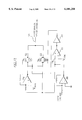
- FIG. 7 is a more detailed circuit diagram of the circuit of FIG. 6;
- FIG. 8 is a schematic diagram of a hearing aid apparatus having automatic ambient-noise-level dependent switching between microphones
- FIG. 9 is a schematic diagram of a hearing aid apparatus having automatic ambient-noise-level dependent switching between microphones wherein the switching is performed by a fader circuit;
- FIGS. 10-12 are graphs showing various signals of the circuit of FIG. 9 as a function of sound pressure level
- FIGS. 13-15 are schematic block diagrams of various constructions of a hearing aid apparatus and its associated components employing automatic switching between an omnidirectional microphone, a first order directional microphone, and a second order directional microphone;
- FIGS. 16 and 17 are cross sectional views showing the mechanical construction of various microphones suitable for use in the various hearing aid embodiments set forth herein;
- FIG. 18 is a perspective view of a hearing aid constructed in accordance with the invention as inserted into an ear;
- FIG. 19 is a cross sectional view showing certain mechanical structures of one embodiment of a hearing aid in accordance with the invention.
- FIG. 20 is a perspective view showing an alternate mechanical construction of the second order microphone shown in FIG. 19.
- FIG. 21 is a front view of the diffraction scoop used in FIG. 19.
- a hearing aid apparatus constructed in accordance with one embodiment of the invention is shown generally at 10 of FIG. 1. As illustrated, the hearing aid apparatus 10 utilizes both an omnidirectional microphone 15 and a directional microphone 20 of at least the first order. Each of the microphones 15,20 is used to convert sound waves into electrical output signals corresponding to the sound waves.
- the free space directional response of a typical omnidirectional microphone is shown by line 21 in FIG. 2 while the corresponding frequency response of such a microphone is shown by line 25 of FIG. 3.
- the directional and frequency response of a typical omnidirectional microphone make it quite suitable for use in low noise environments when it is desirable to hear sound from all directions. Such an omnidirectional microphone is particularly suited for listening to a music concert or the like.
- the free space directional response of one type of a first order directional microphone is set forth by line 26 in FIG. 4 and the corresponding frequency response is shown by line 30 of FIG. 2.
- the first order directional microphone tends to reject sound coming from the side and rear of the hearing aid wearer.
- the directivity of a first-order directional microphone may be used to improve the signal-to-noise ratio of the hearing aid since it rejects a portion of the noise coming from the sides and behind the hearing aid wearer.
- the first order directional microphone experiences decreased sensitivity to low frequency sound waves, sensitivity dropping off at a rate of 6 dB per octave below approximately 2 KHz.
- the free space directional response of one type of a second order directional microphone is set forth by line 31 in FIG. 5 and the corresponding frequency response is shown by line 35 of FIG. 2.
- the second order directional microphone is even more directional than the first order microphone and, as such, tends to improve the signal-to-noise ratio of the hearing aid to an even greater degree than the first order microphone.
- the second order directional microphone is even less sensitive to low frequency sound waves than its first order counterpart, sensitivity dropping off at a rate of 12 dB per octave below approximately 2 KHz.
- the output of the directional microphone 20 is AC coupled to the input of an equalizer circuit 40 through capacitor 45.
- the equalizer circuit 40 at least partially equalizes the amplitude of the low frequency components of the electrical signal output from the directional microphone 20 with the amplitude of the mid and high frequency components of the electrical signal output. This equalization serves to compensate for the decreased sensitivity that the directional microphone provides at lower frequencies.
- the equalizer circuit 40 provides the equalized signal at output line 50.
- the equalizer circuit 40 raises the noise level of the hearing aid system.
- the noise level is significantly raised when a second order microphone is equalized. This noise is quite noticeable to the hearing aid wearer when the hearing aid is used in low ambient noise situations, but tends to become masked in high ambient noise level situations. It is in high ambient noise level situations that the directionality of the directional microphone is most useful for increasing the signal to noise ratio of the hearing aid system.
- the equalized electrical signal output from the equalizer circuit 40 and the electrical signal output from the omnidirectional microphone 15 are supplied to opposite terminals of a SPDT switch 55 that has its pole terminal connected to the input of a hearing aid amplifier 60.
- the electrical signal output from omnidirectional microphone 15 is AC coupled through capacitor 62.
- the hearing aid amplifier 60 may be of the type shown and described in U.S. Pat. No. 5,131,046, to Killion et al, the teachings of which are hereby incorporated by reference.
- the SPDT switch 55 has at least two switching states. In a first switching state, the electrical signal from the omnidirectional microphone 15 is connected to the input of the hearing aid amplifier 60 to the exclusion of the equalized signal from the equalizer circuit 40. In a second switching state, the equalized electrical signal from the equalizer circuit 40 is connected to the input of the hearing aid amplifier 60 to the exclusion of the electrical signal from the omnidirectional microphone 15.
- Microphone selection such as is disclosed herein, allows optimization of the signal-to-noise ratio of the hearing aid system dependent on the ambient noise conditions. As will be set forth in more detail below, such selection can be done either manually or automatically.
- FIG. 6 shows another embodiment of a hearing aid system 10.
- the hearing aid system 10 employs two first-order directional microphones 65 and 70.
- the electrical signal output of directional microphone 70 is AC coupled to the positive input of a summing circuit 75 while the electrical signal output of directional microphone 65 is AC coupled to the negative input of the summing circuit 75.
- the directional microphones 65,70 have matched characteristics.
- the resultant electrical signal output on line 80 of the summing circuit 75 has second order directional and frequency response characteristics and is supplied to the input of the equalizer circuit 40.
- FIG. 7 A more detailed schematic diagram of the system shown in FIG. 6 is given in FIG. 7.
- the electrical signal output of first order directional microphone 65 is AC coupled through capacitor 85 to the input of an inverting circuit, shown generally at 90.
- the inverting circuit 90 includes an inverting amplifier 95, resistors 100 and 105, and balance resistor 110.
- the electrical signal output of first order microphone 70 is AC coupled through capacitor 115 to resistor 120 which, in turn, is connected to supply the electrical signal output to summing junction 80.
- the signal at summing junction 80 is supplied to the input of the equalizer circuit 40.
- the equalizer circuit 40 includes inverting amplifier 125, resistors 130 and 135, and capacitor 140.
- the equalized electrical signal output from the equalizer circuit 40 is supplied to switch 55 on line 145.
- the components of the embodiment shown in FIG. 7 may have the following values and be of the following component types:
- the SPDT switch 55 can be replaced by an automatic switching system that switches between the directional microphone and the omnidirectional microphone dependent on sensed ambient noise levels. Such alternative embodiments are shown in FIGS. 8 and 9.
- the embodiment of FIG. 8 includes a directional microphone 20 of at least the first order and an omnidirectional microphone 15.
- the output of directional microphone 20 is supplied to the input of equalizer circuit 40 through capacitor 45.
- the equalized output signal from the equalizer is supplied on output line 50 to an FET switch 150.
- the output signal from omnidirectional microphone 15 is supplied through capacitor 62 to a further FET switch 155.
- Each FET switch 150 and 155 includes two complementary FETs 160 and 165 arranged as series pass devices. Where the DC signal level at the input of hearing aid amplifier 60 is 0V (such as with the hearing aid amplifier design set forth in the above-noted U.S. Pat. No. 5,131,046), only a single FET (i.e., an N-channel FET) need be employed.
- the FET switches 150 and 155 receive respective control signals from a noise comparison circuit, shown generally at 170, to control their respective series pass resistances.
- the noise comparison circuit 170 includes a noise sensing circuit portion and a control circuit portion.
- the noise sensing circuit-portion includes an amplifier 175 that accepts the electrical output signal from omnidirectional microphone 15.
- the amplified output signal is supplied to the input of a rectifier circuit 180 which rectifies the amplified signal to provide a DC signal output on line 185 that is indicative of the ambient noise level detected by omnidirectional microphone 15.
- the control circuit portion includes comparator 190 and logic inverter 195.
- the DC signal output from the rectifier circuit is supplied to the positive input of comparator 190 for comparison to a reference signal V REF that is supplied to the negative input of the comparator 190.
- the output of comparator 190 is a binary signal and is supplied as a control signal to FET switch 150.
- the output of the comparator is also supplied to the input of logic inverter 195, the output of which is supplied as a control signal to FET switch 155.
- the signal V REF is set to a magnitude representative of a reference ambient noise level at which the hearing aid apparatus is to switch between the directional and omnidirectional microphones 20 and 15.
- the signal V REF can be set to a level representative of a 65 dB ambient noise level.
- FET switch 150 will have a low series pass resistance level and will connect the equalized output signal at line 50 to the input of the hearing aid amplifier 60 while FET switch 155 will have a high series pass resistance and will effectively disconnect the electrical signal output of omnidirectional microphone 15 from the input of the hearing aid amplifier 60.
- FET switch 155 When the ambient noise level drops below 65 dB, FET switch 155 will have a low series pass resistance level and will connect the electrical signal output of microphone 15 at line 200 to the input of the hearing aid amplifier 60 while FET switch 150 will have a high series pass resistance and will effectively disconnect the equalized signal output on line 50 from the input of the hearing aid amplifier 60.
- the comparator 190 may be designed to have a certain degree of hysteresis.
- the reference signal V REF may be variable and may be set to a level that is optimized for the particular hearing aid wearer.
- reference signal V REF may be supplied from a voltage divider having a trimmer pot as one of its resistive components (not shown). The trimmer pot may be adjusted to set the optimal V REF value.
- FIG. 9 A further embodiment of a hearing aid apparatus that employs automatic switching is set forth in FIG. 9.
- the circuit of FIG. 9 is the same as that shown in FIG. 8 except that the noise comparison circuit 170 is replaced with a fader circuit, shown generally at 205.
- the fader circuit 205 includes an amplifier 210 connected to receive the electrical signal output of omnidirectional microphone 15 through capacitor 62.
- the amplified signal is supplied to the input of a logarithmic rectifier 215 such as is shown and described in the aforementioned U.S. Pat. No. 5,131,046, but with reversed output polarity.
- the output of the logarithmic rectifier 215 is supplied as a control signal VC1 to FET switch 155 and is also supplied to the input of an inverting amplifier circuit 220 having a gain of 1. Where the output range of the logarithmic rectifier is insufficient to drive FET switch 155, an amplifier may be used the output of which would be supplied as the control signal VC1 and to the input of inverting amplifier circuit 220.
- the output of inverting amplifier 220 is supplied as a control signal VC2 to FET switch 150.
- FIG. 10 is a graph of the control voltages VC1 and VC2 as a function of sound pressure level.
- the ambient noise level increases there is an increase in the sound pressure level at omnidirectional microphone 15. This causes an increase of the level of control voltage VC1 while resulting in a corresponding decrease of the level of control voltage VC2.
- the sound pressure level at omnidirectional microphone 15 increases as ambient noise level increases.
- This causes an increase of the level of control voltage VC1 while resulting in a corresponding decrease of the level of control voltage VC2.
- ambient noise level decreases there is a decrease in the sound pressure level at omnidirectional microphone 15. This causes an increase of the level of control voltage VC2 while resulting in a corresponding decrease of the level of control voltage VC1.
- FIG. 11 is a graph of the resistances RS1 and RS2 respectively of FET switches 155 and 150 as a function of sound pressure level.
- the ambient noise level and, thus, the sound pressure level increases, there is a corresponding increase in the series resistance RS1 of FET switch 155 and a decrease in the series resistance RS2 of FET switch 150.
- the hearing aid amplifier 60 At the input to the hearing aid amplifier 60, there is thus an increase in the relative level of the signal received from directional microphone 20 and a decrease in the relative level of the signal received from the omnidirectional microphone 15.
- the ambient noise level and, thus, the sound pressure level decreases, there is a corresponding increase in the series resistance RS2 of FET switch 150 and a decrease in the series resistance RS1 of FET switch 155.
- the omnidirectional microphone 15 is effectively completely connected to the input of the hearing aid amplifier 60 while the directional microphone 20 is effectively disconnected from the input of the hearing aid amplifier 60.
- SPL2 Sound pressure level
- the directional microphone 20 is effectively completely connected to the input of the hearing aid amplifier 60 while the omnidirectional microphone 15 is effectively disconnected from the input of the hearing aid amplifier 60.
- SPL3 Sound pressure level
- the fader circuit gradually decreases the relative amplitude of the equalized signal supplied to the hearing aid amplifier while gradually increasing the relative amplitude of the electrical signal supplied to the hearing aid amplifier from the omnidirectional microphone as the level of ambient noise decreases.
- the fader circuit gradually increases the relative amplitude of the equalized signal supplied to the hearing aid amplifier while gradually relative decreasing the amplitude of the electrical signal supplied to the hearing aid amplifier from the omnidirectional microphone as the level of the ambient noise increases.
- the fader circuit 205 may be designed so that the voltage at the input to the hearing aid amplifier 60 is a monotonic function of sound pressure level. This characteristic is illustrated in FIG. 12. A hearing aid apparatus having such characteristic would not present any noticeable deviation in sound output to the user as the apparatus transitions through the various sound pressure level states with variations in ambient noise levels.
- an amplified telecoil may be substituted for omnidirectional microphone 15 in FIG. 8, with V ref chosen to provide a switch in the output of comparator 190 when a sounding telephone is brought to the ear.
- Control of FET switch 155 is through the signal output of comparator 190 and control of FET switch 150 is through the output of inverter 195.
- the fader circuit of FIG. 9 may be used.
- FIG. 13 shows an embodiment of a hearing aid employing an omnidirectional microphone 230, a first order directional microphone 235, and a second order directional microphone 240.
- the directional microphones 235, 240 are AC coupled to respective equalizer circuits 245, 250.
- the output of equalizer circuit 245 is supplied to FET switch 255 and the output of equalizer 250 is supplied to FET switch 260.
- Ambient noise is sensed at omnidirectional microphone 230, the output of which is supplied to amplifier 265 and therefrom to logarithmic rectifier 270.
- the output of microphone 230 is also AC coupled to FET switch 275.
- the output of logarithmic rectifier 270 is supplied to a first inverting amplifier circuit 280, a second inverting amplifier circuit 285, and directly to control FET switch 275.
- the gain of the inverting amplifiers 280 and 285 are chosen so that the omnidirectional microphone output signal dominates at the input of hearing aid amplifier 60 in low ambient noise conditions, the first order directional microphone output signal dominates at mid-level ambient noise conditions, and the second order microphone output dominates at high ambient noise conditions.
- FIG. 14 shows an alternative design of the circuit of FIG. 13.
- two first order microphones 290 and 295 are employed along with omnidirectional microphone 230.
- First order microphone 295 functions both as a first order directional microphone and as a portion of a second order directional microphone when the output of microphone 290 is subtracted from the output of microphone 295 at junction 300.
- Equalizer 245 is not utilized in this circuit for the sake of economy and will not drastically effect hearing aid performance since the lack of low frequency sensitivity of a first order microphone is within a tolerable range without equalization.
- FIG. 15 shows an alternative circuit for driving the FET switch of the first order microphone 295 in FIG. 14 or first order microphone 235 in FIG. 13.
- the output of logarithmic rectifier 270 is supplied to the input of an inverting amplifier circuit 305.
- the output of inverting amplifier 305 is supplied to the input of a further inverting amplifier circuit 310, to an FET switch 315, and to the positive input of comparator 320 for comparison with a comparison voltage V COM .
- the output of inverting amplifier circuit 310 is biased by a voltage V BIAS and supplied to FET switch 325.
- Comparator 320 compares the voltage at line 330 with the voltage V COM and supplies a binary state signal output based on the comparison.
- the binary output is supplied as the control voltage to FET switch 345 and to the input of a logic inverter 335.
- the output of logic inverter 335 is supplied as the control voltage to FET switch 315.
- the outputs of the FET switches 315 and 325 are supplied as the control voltage for the FET switch associated with the first order microphone response.
- V COM represents the sound pressure level at which the first order microphone output to the hearing aid amplifier begins to be attenuated.
- the output of inverting amplifier 305 is supplied as the control voltage to the first order microphone FET switch through FET switch 315 for voltage levels below V COM and gradually increases up to that point with increasing sound pressure level.
- the output of inverting amplifier 305 is effectively disconnected from the first order FET switch and is replaced by the voltage output of inverting amplifier 310 which gradually decreases with increasing sound pressure level.
- the magnitude of V BIAS is chosen so that there is a smooth transition of the control voltage output at line 340.
- FIG. 16 shows an omnidirectional pressure type microphone 15 commonly used in hearing aid applications.
- the omnidirectional microphone 15 includes a hollow body portion 345 having a diaphragm 350 disposed therein.
- An inlet tube 355 extends from the hollow body portion 345 and engages extension tubing 360 to form a sound port 365. Sound received at effective sensing point 370 will be transmitted into the hollow body portion 345 to vibrate diaphragm 350 which transduces the sound wave into an electrical signal.
- FIG. 17 illustrates a gradient first order directional microphone 20 that may be employed in the hearing aid apparatus set forth herein.
- the directional microphone 20 includes a hollow body portion 375 having a diaphragm 380 disposed therein that divides the interior of the hollow body portion 375 into two chambers 385 and 390.
- a first inlet tube 395 extends from the hollow body portion 375 and is connected to extension tube 395 to define a first sound port shown generally at 400.
- a second inlet tube 405 extends from the hollow body portion 375 and is connected to extension tube 410 to define a second sound port shown generally at 415.
- a time delay acoustical network, defined generally at 420 may also be employed.
- the effective port spacing D determines the sensitivity of the microphone as well as its high frequency response. Sound waves received at sound ports 400 and 415 will respectively travel to chambers 390 and 385 to cause a differential pressure force on diaphragm 380. This differential pressure force is transduced by diaphragm 380 into an electrical output signal.
- FIGS. 18-21 show various mechanical constructions that may be employed in the hearing aid embodiments described above.
- the hearing aid includes a housing 420 having an aperature over which a face plate 425 is disposed.
- the housing 420 is sized to fit within the ear 430 of a hearing aid user and contains the hearing aid amplifier and speaker (not shown) as well as an omnidirectional microphone and at least one directional microphone.
- a switch 435 may optionally be provided through the face plate 425 to allow a hearing aid user to manually switch between the omnidirectional microphone and the directional microphone.
- the sound port 440 of the omnidirectional microphone extends through face plate 425.
- the directional microphone is a second order directional microphone that is constructed from two first order gradient directional microphones 445 and 450 of the type described above.
- Each first order directional microphone includes a respective pair of spaced apart sound ports 400, 415, and 400', 415'.
- the sound ports 400, 415, 400' and 415' of the first order microphones may be arranged along line 455 as shown in FIG. 18 so that they are generally collinear.
- the second order directional microphone formed from the two first order directional microphones will tend to be highly sensitive to frontal sound waves received in the direction shown by arrow 460 while being generally insensitive to rear sound waves received in the direction shown by arrow 465.
- FIG. 20 An alternative construction of a second order microphone formed from two first order microphones is shown in FIG. 20. Rather than having all four sound ports connected through face plate 425, this embodiment has three sound ports.
- the central sound port 470 is formed by interconnecting sound port 415' of directional microphone 445 to sound port 400 of directional microphone 450.
- the diameter of extension tube 475 is approximately 1.4 times the diameter of the extension tubes 395' and 410 of sound ports 400' and 415 to compensate for this interconnection.
- FIG. 19 illustrates two additional mechanical structures that can be used to increase the signal-to-noise ratio of the hearing aid.
- a pair of diffraction scoops 480 may be disposed respectively above sound ports 400' and 415.
- the diffraction scoops 480 tend to increase the effective port spacing and thus increase the sensitivity of the directional microphone.
- a front view of a diffraction scoop 480 is shown in FIG. 21.
- a wind screen 485 is disposed over the diffraction scoops 480 and at least a portion of face plate 425.
- the wind screen 485 may be in the form of a porous screen or a multiply perforate molded housing.
- the hearing aid apparatus disclosed herein results from a new understanding of the problems associated with the use of directional microphones in hearing aids.
- a first understanding is that directional microphones, particularly second-order directional microphones, offer the possibility of an expected directivity index of some 9.0 dB in head-worn applications. The improvement over an omni-directional head-worn microphone thus becomes an attractive 6 dB at high frequencies and nearly 9 dB at low frequencies.
- the improvement in effective signal-to-noise ratio for speech of 3-4 dB for a first-order directional microphone might reasonably be extrapolated to an expected 6.5-7.5 dB improvement in single-to-noise ratio for a second-order directional microphone.
Landscapes
- Health & Medical Sciences (AREA)
- General Health & Medical Sciences (AREA)
- Otolaryngology (AREA)
- Physics & Mathematics (AREA)
- Engineering & Computer Science (AREA)
- Acoustics & Sound (AREA)
- Signal Processing (AREA)
- Neurosurgery (AREA)
- Circuit For Audible Band Transducer (AREA)
- Transmitters (AREA)
Abstract
Description
______________________________________ Component Description ______________________________________ 100, 10585, 115 .027MF 110 25K.sub.variable 120 15K 130 27K 100K 1351M 140 56095, 125 LX 509 of Gennum Corp. ______________________________________ pf
Claims (17)
Priority Applications (5)
| Application Number | Priority Date | Filing Date | Title |
|---|---|---|---|
| US08/955,271 US6101258A (en) | 1993-04-13 | 1997-10-21 | Hearing aid having plural microphones and a microphone switching system |
| US09/624,805 US6327370B1 (en) | 1993-04-13 | 2000-07-24 | Hearing aid having plural microphones and a microphone switching system |
| US09/969,064 US7103191B1 (en) | 1993-04-13 | 2001-10-02 | Hearing aid having second order directional response |
| US09/999,133 US20020057815A1 (en) | 1993-04-13 | 2001-11-01 | Hearing aid having switchable first and second order directional responses |
| US11/586,480 US7590253B2 (en) | 1993-04-13 | 2006-10-25 | Hearing aid having switchable first and second order directional responses |
Applications Claiming Priority (3)
| Application Number | Priority Date | Filing Date | Title |
|---|---|---|---|
| US08/046,241 US5524056A (en) | 1993-04-13 | 1993-04-13 | Hearing aid having plural microphones and a microphone switching system |
| US63251796A | 1996-04-12 | 1996-04-12 | |
| US08/955,271 US6101258A (en) | 1993-04-13 | 1997-10-21 | Hearing aid having plural microphones and a microphone switching system |
Related Parent Applications (1)
| Application Number | Title | Priority Date | Filing Date |
|---|---|---|---|
| US63251796A Continuation | 1993-04-13 | 1996-04-12 |
Related Child Applications (1)
| Application Number | Title | Priority Date | Filing Date |
|---|---|---|---|
| US09/624,805 Continuation US6327370B1 (en) | 1993-04-13 | 2000-07-24 | Hearing aid having plural microphones and a microphone switching system |
Publications (1)
| Publication Number | Publication Date |
|---|---|
| US6101258A true US6101258A (en) | 2000-08-08 |
Family
ID=21942383
Family Applications (6)
| Application Number | Title | Priority Date | Filing Date |
|---|---|---|---|
| US08/046,241 Expired - Lifetime US5524056A (en) | 1993-04-13 | 1993-04-13 | Hearing aid having plural microphones and a microphone switching system |
| US08/955,271 Expired - Lifetime US6101258A (en) | 1993-04-13 | 1997-10-21 | Hearing aid having plural microphones and a microphone switching system |
| US09/624,805 Expired - Fee Related US6327370B1 (en) | 1993-04-13 | 2000-07-24 | Hearing aid having plural microphones and a microphone switching system |
| US09/969,064 Expired - Fee Related US7103191B1 (en) | 1993-04-13 | 2001-10-02 | Hearing aid having second order directional response |
| US09/999,133 Abandoned US20020057815A1 (en) | 1993-04-13 | 2001-11-01 | Hearing aid having switchable first and second order directional responses |
| US11/586,480 Expired - Fee Related US7590253B2 (en) | 1993-04-13 | 2006-10-25 | Hearing aid having switchable first and second order directional responses |
Family Applications Before (1)
| Application Number | Title | Priority Date | Filing Date |
|---|---|---|---|
| US08/046,241 Expired - Lifetime US5524056A (en) | 1993-04-13 | 1993-04-13 | Hearing aid having plural microphones and a microphone switching system |
Family Applications After (4)
| Application Number | Title | Priority Date | Filing Date |
|---|---|---|---|
| US09/624,805 Expired - Fee Related US6327370B1 (en) | 1993-04-13 | 2000-07-24 | Hearing aid having plural microphones and a microphone switching system |
| US09/969,064 Expired - Fee Related US7103191B1 (en) | 1993-04-13 | 2001-10-02 | Hearing aid having second order directional response |
| US09/999,133 Abandoned US20020057815A1 (en) | 1993-04-13 | 2001-11-01 | Hearing aid having switchable first and second order directional responses |
| US11/586,480 Expired - Fee Related US7590253B2 (en) | 1993-04-13 | 2006-10-25 | Hearing aid having switchable first and second order directional responses |
Country Status (5)
| Country | Link |
|---|---|
| US (6) | US5524056A (en) |
| EP (1) | EP0664071B2 (en) |
| AT (1) | ATE221303T1 (en) |
| DE (1) | DE69431037T3 (en) |
| WO (1) | WO1994024834A1 (en) |
Cited By (57)
| Publication number | Priority date | Publication date | Assignee | Title |
|---|---|---|---|---|
| WO2001052597A1 (en) * | 2000-01-07 | 2001-07-19 | Etymotic Research, Inc. | Transmission detection and switch system for hearing improvement applications |
| US6272229B1 (en) * | 1999-08-03 | 2001-08-07 | Topholm & Westermann Aps | Hearing aid with adaptive matching of microphones |
| US6327370B1 (en) * | 1993-04-13 | 2001-12-04 | Etymotic Research, Inc. | Hearing aid having plural microphones and a microphone switching system |
| US6424721B1 (en) * | 1998-03-09 | 2002-07-23 | Siemens Audiologische Technik Gmbh | Hearing aid with a directional microphone system as well as method for the operation thereof |
| US6510230B2 (en) | 2001-01-02 | 2003-01-21 | Theodore J. Marx | Support device for a behind-the-ear hearing aid |
| US20030055311A1 (en) * | 1996-02-15 | 2003-03-20 | Neukermans Armand P. | Biocompatible transducers |
| US20030059073A1 (en) * | 2000-09-11 | 2003-03-27 | Micro Ear Technology, Inc., D/B/A Micro-Tech | Integrated automatic telephone switch |
| US20030072465A1 (en) * | 2001-10-17 | 2003-04-17 | Eghart Fischer | Method for the operation of a hearing aid as well as a hearing aid |
| US20030091197A1 (en) * | 2001-11-09 | 2003-05-15 | Hans-Ueli Roeck | Method for operating a hearing device as well as a hearing device |
| US20030169891A1 (en) * | 2002-03-08 | 2003-09-11 | Ryan Jim G. | Low-noise directional microphone system |
| US6633645B2 (en) | 2000-09-11 | 2003-10-14 | Micro Ear Technology, Inc. | Automatic telephone switch for hearing aid |
| US6651481B1 (en) | 2001-10-12 | 2003-11-25 | The United States Of America As Represented By The United States National Aeronautics And Space Administration | Method and apparatus for characterizing pressure sensors using modulated light beam pressure |
| US20030235319A1 (en) * | 2002-06-24 | 2003-12-25 | Siemens Audiologische Technik Gmbh | Hearing aid system with a hearing aid and an external processor unit |
| US20040052391A1 (en) * | 2002-09-12 | 2004-03-18 | Micro Ear Technology, Inc. | System and method for selectively coupling hearing aids to electromagnetic signals |
| US20040052392A1 (en) * | 2002-09-16 | 2004-03-18 | Sacha Mike K. | Switching structures for hearing aid |
| US20040115684A1 (en) * | 2001-01-31 | 2004-06-17 | Jean-Marc Costa | Method for genotype determination |
| US20040114772A1 (en) * | 2002-03-21 | 2004-06-17 | David Zlotnick | Method and system for transmitting and/or receiving audio signals with a desired direction |
| US20040193853A1 (en) * | 2001-04-20 | 2004-09-30 | Maier Klaus D. | Program-controlled unit |
| US20040240692A1 (en) * | 2000-12-28 | 2004-12-02 | Julstrom Stephen D. | Magnetic coupling adaptor |
| US6876749B1 (en) * | 1999-07-12 | 2005-04-05 | Etymotic Research, Inc. | Microphone for hearing aid and communications applications having switchable polar and frequency response characteristics |
| US20050157897A1 (en) * | 2002-03-20 | 2005-07-21 | Oleg Saltykov | Hearing instrument |
| US20060013420A1 (en) * | 2002-09-16 | 2006-01-19 | Sacha Michael K | Switching structures for hearing aid |
| US20060291679A1 (en) * | 2005-02-25 | 2006-12-28 | Burns Thomas H | Microphone placement in hearing assistance devices to provide controlled directivity |
| US20070014419A1 (en) * | 2003-12-01 | 2007-01-18 | Dynamic Hearing Pty Ltd. | Method and apparatus for producing adaptive directional signals |
| US7206426B1 (en) | 2000-01-07 | 2007-04-17 | Etymotic Research, Inc. | Multi-coil coupling system for hearing aid applications |
| EP1919255A2 (en) | 2003-05-19 | 2008-05-07 | Widex A/S | A hearing aid |
| US20080167868A1 (en) * | 2007-01-04 | 2008-07-10 | Dimitri Kanevsky | Systems and methods for intelligent control of microphones for speech recognition applications |
| US20080306745A1 (en) * | 2007-05-31 | 2008-12-11 | Ecole Polytechnique Federale De Lausanne | Distributed audio coding for wireless hearing aids |
| US20090074214A1 (en) * | 2007-09-13 | 2009-03-19 | Bionica Corporation | Assistive listening system with plug in enhancement platform and communication port to download user preferred processing algorithms |
| US20090074216A1 (en) * | 2007-09-13 | 2009-03-19 | Bionica Corporation | Assistive listening system with programmable hearing aid and wireless handheld programmable digital signal processing device |
| US20090076804A1 (en) * | 2007-09-13 | 2009-03-19 | Bionica Corporation | Assistive listening system with memory buffer for instant replay and speech to text conversion |
| US20090074203A1 (en) * | 2007-09-13 | 2009-03-19 | Bionica Corporation | Method of enhancing sound for hearing impaired individuals |
| US20090076825A1 (en) * | 2007-09-13 | 2009-03-19 | Bionica Corporation | Method of enhancing sound for hearing impaired individuals |
| US20090076816A1 (en) * | 2007-09-13 | 2009-03-19 | Bionica Corporation | Assistive listening system with display and selective visual indicators for sound sources |
| US20090074206A1 (en) * | 2007-09-13 | 2009-03-19 | Bionica Corporation | Method of enhancing sound for hearing impaired individuals |
| US20090076636A1 (en) * | 2007-09-13 | 2009-03-19 | Bionica Corporation | Method of enhancing sound for hearing impaired individuals |
| US20090094817A1 (en) * | 2007-10-11 | 2009-04-16 | Killion Mead C | Directional Microphone Assembly |
| US20090129608A1 (en) * | 2007-01-11 | 2009-05-21 | Siemens Audiologische Technik Gmbh | Method for reducing interference powers and corresponding acoustic system |
| US20090252357A1 (en) * | 2008-04-07 | 2009-10-08 | Siemens Medical Instruments Pte. Ltd. | Method for switching a hearing device between two operating states and hearing device |
| US20090316916A1 (en) * | 2008-05-23 | 2009-12-24 | Analog Devices, Inc. | Wide Dynamic Range Microphone |
| US20100172531A1 (en) * | 2008-12-31 | 2010-07-08 | Starkey Laboratories, Inc. | Method and apparatus for hearing assistance device microphones |
| US7881486B1 (en) * | 1996-12-31 | 2011-02-01 | Etymotic Research, Inc. | Directional microphone assembly |
| EP2337374A1 (en) * | 2009-12-17 | 2011-06-22 | Sunitec Enterprise Co. Ltd. | Dual-functional earphone |
| US8041066B2 (en) | 2007-01-03 | 2011-10-18 | Starkey Laboratories, Inc. | Wireless system for hearing communication devices providing wireless stereo reception modes |
| US8147544B2 (en) | 2001-10-30 | 2012-04-03 | Otokinetics Inc. | Therapeutic appliance for cochlea |
| US20120207324A1 (en) * | 2006-07-25 | 2012-08-16 | Analog Devices, Inc. | Multiple Microphone System |
| US20140369516A1 (en) * | 2013-06-13 | 2014-12-18 | Samsung Electronics Co., Ltd. | Method for cancelling noise and electronic device thereof |
| US20150131819A1 (en) * | 2013-11-08 | 2015-05-14 | Infineon Technologies Ag | Microphone package and method for generating a microphone signal |
| US9036823B2 (en) | 2006-07-10 | 2015-05-19 | Starkey Laboratories, Inc. | Method and apparatus for a binaural hearing assistance system using monaural audio signals |
| US9363608B2 (en) | 2011-01-07 | 2016-06-07 | Omron Corporation | Acoustic transducer |
| US9380380B2 (en) | 2011-01-07 | 2016-06-28 | Stmicroelectronics S.R.L. | Acoustic transducer and interface circuit |
| US9774961B2 (en) | 2005-06-05 | 2017-09-26 | Starkey Laboratories, Inc. | Hearing assistance device ear-to-ear communication using an intermediate device |
| US10003379B2 (en) | 2014-05-06 | 2018-06-19 | Starkey Laboratories, Inc. | Wireless communication with probing bandwidth |
| US10212682B2 (en) | 2009-12-21 | 2019-02-19 | Starkey Laboratories, Inc. | Low power intermittent messaging for hearing assistance devices |
| US20190110124A1 (en) * | 2017-10-07 | 2019-04-11 | Point Source Audio, Inc. | Wearable Microphone Housing with Built-in Redundancy |
| US10306375B2 (en) | 2015-02-04 | 2019-05-28 | Mayo Foundation For Medical Education And Research | Speech intelligibility enhancement system |
| US11153472B2 (en) | 2005-10-17 | 2021-10-19 | Cutting Edge Vision, LLC | Automatic upload of pictures from a camera |
Families Citing this family (191)
| Publication number | Priority date | Publication date | Assignee | Title |
|---|---|---|---|---|
| DE69531413T2 (en) * | 1994-05-18 | 2004-04-15 | Nippon Telegraph And Telephone Corp. | Transceiver with an acoustic transducer of the earpiece type |
| US5867581A (en) * | 1994-10-14 | 1999-02-02 | Matsushita Electric Industrial Co., Ltd. | Hearing aid |
| US6978159B2 (en) * | 1996-06-19 | 2005-12-20 | Board Of Trustees Of The University Of Illinois | Binaural signal processing using multiple acoustic sensors and digital filtering |
| US6987856B1 (en) | 1996-06-19 | 2006-01-17 | Board Of Trustees Of The University Of Illinois | Binaural signal processing techniques |
| US5825898A (en) * | 1996-06-27 | 1998-10-20 | Lamar Signal Processing Ltd. | System and method for adaptive interference cancelling |
| US5757933A (en) * | 1996-12-11 | 1998-05-26 | Micro Ear Technology, Inc. | In-the-ear hearing aid with directional microphone system |
| US5878147A (en) * | 1996-12-31 | 1999-03-02 | Etymotic Research, Inc. | Directional microphone assembly |
| US6151399A (en) | 1996-12-31 | 2000-11-21 | Etymotic Research, Inc. | Directional microphone system providing for ease of assembly and disassembly |
| US6275596B1 (en) | 1997-01-10 | 2001-08-14 | Gn Resound Corporation | Open ear canal hearing aid system |
| US6178248B1 (en) | 1997-04-14 | 2001-01-23 | Andrea Electronics Corporation | Dual-processing interference cancelling system and method |
| US7027608B2 (en) * | 1997-07-18 | 2006-04-11 | Gn Resound North America | Behind the ear hearing aid system |
| DK0847227T3 (en) * | 1998-03-02 | 2003-12-22 | Phonak Ag | Hearing aid |
| US6201875B1 (en) | 1998-03-17 | 2001-03-13 | Sonic Innovations, Inc. | Hearing aid fitting system |
| US6104820A (en) * | 1998-04-16 | 2000-08-15 | Soza; Gersan | Musical massager |
| US6000492A (en) * | 1998-06-29 | 1999-12-14 | Resound Corporation | Cerumen block for sound delivery system |
| US6009183A (en) * | 1998-06-30 | 1999-12-28 | Resound Corporation | Ambidextrous sound delivery tube system |
| US6681022B1 (en) | 1998-07-22 | 2004-01-20 | Gn Resound North Amerca Corporation | Two-way communication earpiece |
| US6597793B1 (en) | 1998-08-06 | 2003-07-22 | Resistance Technology, Inc. | Directional/omni-directional hearing aid microphone and housing |
| EP1118248B1 (en) | 1998-09-29 | 2005-03-23 | Siemens Audiologische Technik GmbH | Hearing aid and method for processing microphone signals in a hearing aid |
| DE19856798A1 (en) * | 1998-12-09 | 1999-12-16 | Siemens Audiologische Technik | Hearing aid with multiple channel gain control for frequency selective correction of hearing deficiencies |
| US6681021B1 (en) * | 1998-12-18 | 2004-01-20 | Siemens Hearing Instruments, Inc. | Directional ITE hearing aid using dual-input microphone |
| EP1017252A3 (en) * | 1998-12-31 | 2006-05-31 | Resistance Technology, Inc. | Hearing aid system |
| EP1018854A1 (en) * | 1999-01-05 | 2000-07-12 | Oticon A/S | A method and a device for providing improved speech intelligibility |
| US6363345B1 (en) | 1999-02-18 | 2002-03-26 | Andrea Electronics Corporation | System, method and apparatus for cancelling noise |
| US7460677B1 (en) | 1999-03-05 | 2008-12-02 | Etymotic Research Inc. | Directional microphone array system |
| US6094492A (en) * | 1999-05-10 | 2000-07-25 | Boesen; Peter V. | Bone conduction voice transmission apparatus and system |
| WO2000076268A2 (en) * | 1999-06-02 | 2000-12-14 | Siemens Audiologische Technik Gmbh | Hearing aid device, comprising a directional microphone system and a method for operating a hearing aid device |
| WO2001001732A1 (en) * | 1999-06-24 | 2001-01-04 | Tøpholm & Westermann APS | Hearing aid with controllable directional characteristics |
| JP4448616B2 (en) * | 1999-10-14 | 2010-04-14 | フォーナック アーゲー | Hearing aid, adjustment method and manufacturing method thereof |
| US6594367B1 (en) | 1999-10-25 | 2003-07-15 | Andrea Electronics Corporation | Super directional beamforming design and implementation |
| US20030031339A1 (en) * | 2000-01-13 | 2003-02-13 | Marshall Bowen F. | Packaging and rf shielding for telecoils |
| AU2001226658A1 (en) * | 2000-01-19 | 2001-07-31 | Oticon A/S | In the ear hearing aid |
| WO2001054451A2 (en) | 2000-01-19 | 2001-07-26 | Microtronic Nederland B.V. | A directional microphone assembly |
| US20010028718A1 (en) | 2000-02-17 | 2001-10-11 | Audia Technology, Inc. | Null adaptation in multi-microphone directional system |
| CN1418448A (en) * | 2000-03-14 | 2003-05-14 | 奥迪亚科技股份责任有限公司 | Adaptive microphone matching in multi-microphone directional system |
| WO2001069967A2 (en) * | 2000-03-15 | 2001-09-20 | Knowles Electronics, Llc | Acoustical and electrical switch for a directional microphone |
| US20020001391A1 (en) * | 2000-03-16 | 2002-01-03 | Resistance Technology, Inc. | Acoustic switch with electronic switching capability |
| US20010038699A1 (en) * | 2000-03-20 | 2001-11-08 | Audia Technology, Inc. | Automatic directional processing control for multi-microphone system |
| US7206423B1 (en) | 2000-05-10 | 2007-04-17 | Board Of Trustees Of University Of Illinois | Intrabody communication for a hearing aid |
| DK1312239T3 (en) * | 2000-05-10 | 2007-04-30 | Univ Illinois | Techniques for suppressing interference |
| US7346176B1 (en) * | 2000-05-11 | 2008-03-18 | Plantronics, Inc. | Auto-adjust noise canceling microphone with position sensor |
| AU2001268954A1 (en) * | 2000-06-30 | 2002-01-14 | Sonionmicrotronic Nederland B.V. | A microphone assembly |
| US7116792B1 (en) | 2000-07-05 | 2006-10-03 | Gn Resound North America Corporation | Directional microphone system |
| EP1302091A2 (en) * | 2000-07-06 | 2003-04-16 | Sonionmicrotronic Nederland B.V. | A directional microphone |
| US6687187B2 (en) * | 2000-08-11 | 2004-02-03 | Phonak Ag | Method for directional location and locating system |
| DE10045197C1 (en) * | 2000-09-13 | 2002-03-07 | Siemens Audiologische Technik | Operating method for hearing aid device or hearing aid system has signal processor used for reducing effect of wind noise determined by analysis of microphone signals |
| EP1330940B1 (en) * | 2000-10-05 | 2012-03-07 | Etymotic Research, Inc | Directional microphone assembly |
| US6748089B1 (en) | 2000-10-17 | 2004-06-08 | Sonic Innovations, Inc. | Switch responsive to an audio cue |
| US6704422B1 (en) | 2000-10-26 | 2004-03-09 | Widex A/S | Method for controlling the directionality of the sound receiving characteristic of a hearing aid a hearing aid for carrying out the method |
| ATE410901T1 (en) * | 2001-04-18 | 2008-10-15 | Widex As | DIRECTIONAL CONTROL AND METHOD FOR CONTROLLING A HEARING AID |
| DE60336888D1 (en) * | 2002-01-12 | 2011-06-09 | Oticon As | OPPONENT TO WIND NOISE INEFFECTIVE HEARING DEVICE |
| US8098844B2 (en) * | 2002-02-05 | 2012-01-17 | Mh Acoustics, Llc | Dual-microphone spatial noise suppression |
| US7171008B2 (en) * | 2002-02-05 | 2007-01-30 | Mh Acoustics, Llc | Reducing noise in audio systems |
| AU2003226937A1 (en) * | 2002-04-10 | 2003-10-27 | Sonion A/S | Microphone assembly with auxiliary analog input |
| US7136497B2 (en) * | 2002-04-17 | 2006-11-14 | Knowles Electronics, Llc. | Acoustical switch for a directional microphone |
| US7369669B2 (en) † | 2002-05-15 | 2008-05-06 | Micro Ear Technology, Inc. | Diotic presentation of second-order gradient directional hearing aid signals |
| US7602928B2 (en) * | 2002-07-01 | 2009-10-13 | Avaya Inc. | Telephone with integrated hearing aid |
| US20040032957A1 (en) * | 2002-08-14 | 2004-02-19 | Mansy Hansen A. | Sensors and sensor assemblies for monitoring biological sounds and electric potentials |
| DE10249416B4 (en) * | 2002-10-23 | 2009-07-30 | Siemens Audiologische Technik Gmbh | Method for adjusting and operating a hearing aid device and hearing aid device |
| US7162381B2 (en) * | 2002-12-13 | 2007-01-09 | Knowles Electronics, Llc | System and method for facilitating listening |
| DE10260304B3 (en) * | 2002-12-20 | 2004-07-08 | Siemens Audiologische Technik Gmbh | Hearing aid system with side-specific hearing aid devices that can be worn behind the ears |
| US7512448B2 (en) | 2003-01-10 | 2009-03-31 | Phonak Ag | Electrode placement for wireless intrabody communication between components of a hearing system |
| NO20031104D0 (en) * | 2003-03-10 | 2003-03-10 | Meditron Asa | Mini Microphone |
| DE10316287B3 (en) * | 2003-04-09 | 2004-07-15 | Siemens Audiologische Technik Gmbh | Directional microphone for hearing aid having 2 acoustically coupled membranes each coupled to respective sound entry opening |
| CN102291664A (en) * | 2003-05-19 | 2011-12-21 | 唯听助听器公司 | Hearing-aid |
| US7010132B2 (en) * | 2003-06-03 | 2006-03-07 | Unitron Hearing Ltd. | Automatic magnetic detection in hearing aids |
| DE10327890A1 (en) * | 2003-06-20 | 2005-01-20 | Siemens Audiologische Technik Gmbh | Method for operating a hearing aid and hearing aid with a microphone system, in which different directional characteristics are adjustable |
| DE10327889B3 (en) * | 2003-06-20 | 2004-09-16 | Siemens Audiologische Technik Gmbh | Adjusting hearing aid with microphone system with variable directional characteristic involves adjusting directional characteristic depending on acoustic input signal frequency and hearing threshold |
| EP1489882A3 (en) * | 2003-06-20 | 2009-07-29 | Siemens Audiologische Technik GmbH | Method for operating a hearing aid system as well as a hearing aid system with a microphone system in which different directional characteristics are selectable. |
| US7518055B2 (en) * | 2007-03-01 | 2009-04-14 | Zartarian Michael G | System and method for intelligent equalization |
| DE10331956C5 (en) * | 2003-07-16 | 2010-11-18 | Siemens Audiologische Technik Gmbh | Hearing aid and method for operating a hearing aid with a microphone system, in which different Richtcharaktistiken are adjustable |
| DE10334396B3 (en) * | 2003-07-28 | 2004-10-21 | Siemens Audiologische Technik Gmbh | Electrical hearing aid has individual microphones combined to provide 2 microphone units in turn combined to provide further microphone unit with same order directional characteristic |
| DE60304859T2 (en) * | 2003-08-21 | 2006-11-02 | Bernafon Ag | Method for processing audio signals |
| EP1868413B1 (en) * | 2004-02-05 | 2009-07-22 | Phonak AG | Method to operate a hearing device and a hearing device |
| WO2005084074A2 (en) * | 2004-03-01 | 2005-09-09 | Gn Resound A/S | Hearing aid with automatic switching between modes of operation |
| US8942815B2 (en) * | 2004-03-19 | 2015-01-27 | King Chung | Enhancing cochlear implants with hearing aid signal processing technologies |
| US7945056B2 (en) * | 2004-03-23 | 2011-05-17 | Oticon A/S | Listening device with two or more microphones |
| US7443992B2 (en) * | 2004-04-15 | 2008-10-28 | Starkey Laboratories, Inc. | Method and apparatus for modular hearing aid |
| WO2006007441A1 (en) * | 2004-06-16 | 2006-01-19 | Cardo Systems Inc. | Wireless communication headset with microphone switching system |
| DE102005012976B3 (en) * | 2005-03-21 | 2006-09-14 | Siemens Audiologische Technik Gmbh | Hearing aid, has noise generator, formed of microphone and analog-to-digital converter, generating noise signal for representing earpiece based on wind noise signal, such that wind noise signal is partly masked |
| EP1732352B1 (en) * | 2005-04-29 | 2015-10-21 | Nuance Communications, Inc. | Detection and suppression of wind noise in microphone signals |
| US7804975B2 (en) * | 2005-07-01 | 2010-09-28 | Phonak Ag | In-ear device |
| DE102005032292B3 (en) * | 2005-07-11 | 2006-09-21 | Siemens Audiologische Technik Gmbh | Hearing aid for directional hearing has noise detection device to detect noise level of microphones whereby two noise levels can be compared with one another and appropriate control pulse can be displayed at microphone device |
| US8090116B2 (en) * | 2005-11-18 | 2012-01-03 | Holmi Douglas J | Vehicle directional electroacoustical transducing |
| DE102006001886A1 (en) * | 2006-01-13 | 2007-07-19 | Siemens Audiologische Technik Gmbh | Microphone device with multiple silicon microphones for a hearing device |
| EP1819196A1 (en) * | 2006-02-10 | 2007-08-15 | Phonak AG | Method for manufacturing a hearing device and a use of the method |
| EP2897386B2 (en) | 2006-03-03 | 2021-08-04 | GN Hearing A/S | Automatic switching between omnidirectional and directional microphone modes in a hearing aid |
| EP1994788B1 (en) | 2006-03-10 | 2014-05-07 | MH Acoustics, LLC | Noise-reducing directional microphone array |
| US8917876B2 (en) | 2006-06-14 | 2014-12-23 | Personics Holdings, LLC. | Earguard monitoring system |
| EP2044804A4 (en) | 2006-07-08 | 2013-12-18 | Personics Holdings Inc | Personal audio assistant device and method |
| US11450331B2 (en) | 2006-07-08 | 2022-09-20 | Staton Techiya, Llc | Personal audio assistant device and method |
| US8693720B2 (en) | 2006-08-31 | 2014-04-08 | Red Tail Hawk Corporation | Wireless earplug with improved sensitivity and form factor |
| US9525930B2 (en) | 2006-08-31 | 2016-12-20 | Red Tail Hawk Corporation | Magnetic field antenna |
| US8688036B2 (en) | 2006-08-31 | 2014-04-01 | Red Tail Hawk Corporation | Wireless communications headset system employing a loop transmitter that fits around the pinna |
| US7558396B2 (en) * | 2006-09-15 | 2009-07-07 | Fortemedia, Inc. | Microphone module at corner or edge of electronic device |
| US8189837B2 (en) | 2006-12-15 | 2012-05-29 | Phonak Ag | Hearing system with enhanced noise cancelling and method for operating a hearing system |
| US8917894B2 (en) | 2007-01-22 | 2014-12-23 | Personics Holdings, LLC. | Method and device for acute sound detection and reproduction |
| US8254591B2 (en) | 2007-02-01 | 2012-08-28 | Personics Holdings Inc. | Method and device for audio recording |
| KR20080073022A (en) * | 2007-02-05 | 2008-08-08 | 엘지전자 주식회사 | Audio transceiver |
| US11750965B2 (en) | 2007-03-07 | 2023-09-05 | Staton Techiya, Llc | Acoustic dampening compensation system |
| US8111839B2 (en) | 2007-04-09 | 2012-02-07 | Personics Holdings Inc. | Always on headwear recording system |
| US11317202B2 (en) | 2007-04-13 | 2022-04-26 | Staton Techiya, Llc | Method and device for voice operated control |
| WO2008134647A1 (en) | 2007-04-27 | 2008-11-06 | Personics Holdings Inc. | Designer control devices |
| US10194032B2 (en) | 2007-05-04 | 2019-01-29 | Staton Techiya, Llc | Method and apparatus for in-ear canal sound suppression |
| US11856375B2 (en) | 2007-05-04 | 2023-12-26 | Staton Techiya Llc | Method and device for in-ear echo suppression |
| US11683643B2 (en) | 2007-05-04 | 2023-06-20 | Staton Techiya Llc | Method and device for in ear canal echo suppression |
| DE102007021276A1 (en) | 2007-05-07 | 2008-11-13 | Siemens Medical Instruments Pte. Ltd. | Hearing aid equipment, has housing formed in two parts and has frame part, where frame part is formed in one piece with screen with openings |
| US10009677B2 (en) | 2007-07-09 | 2018-06-26 | Staton Techiya, Llc | Methods and mechanisms for inflation |
| DE102007035173A1 (en) * | 2007-07-27 | 2009-02-05 | Siemens Medical Instruments Pte. Ltd. | Method for adjusting a hearing system with a perceptive model for binaural hearing and hearing aid |
| US8130995B2 (en) * | 2007-11-29 | 2012-03-06 | Merry Electronics Co., Ltd. | Earpiece device with microphone |
| DE102008022533B3 (en) * | 2008-05-07 | 2009-10-08 | Siemens Medical Instruments Pte. Ltd. | Method for operating a hearing device and microphone system for a hearing aid |
| EP2134107B1 (en) * | 2008-06-11 | 2013-09-25 | Sonion Nederland B.V. | Method of operating a hearing instrument with improved venting |
| WO2010009504A1 (en) * | 2008-07-24 | 2010-01-28 | Cochlear Limited | Implantable microphone device |
| US8144909B2 (en) | 2008-08-12 | 2012-03-27 | Cochlear Limited | Customization of bone conduction hearing devices |
| US8488799B2 (en) | 2008-09-11 | 2013-07-16 | Personics Holdings Inc. | Method and system for sound monitoring over a network |
| EP2166779B1 (en) * | 2008-09-18 | 2019-05-22 | Sonion Nederland B.V. | An apparatus for outputting sound comprising multiple receivers and a common output channel |
| US8600067B2 (en) | 2008-09-19 | 2013-12-03 | Personics Holdings Inc. | Acoustic sealing analysis system |
| US9129291B2 (en) | 2008-09-22 | 2015-09-08 | Personics Holdings, Llc | Personalized sound management and method |
| CN102210166B (en) * | 2008-10-10 | 2014-04-30 | 美商楼氏电子有限公司 | Acoustic valve mechanisms |
| US8554350B2 (en) | 2008-10-15 | 2013-10-08 | Personics Holdings Inc. | Device and method to reduce ear wax clogging of acoustic ports, hearing aid sealing system, and feedback reduction system |
| DE102008064430B4 (en) | 2008-12-22 | 2012-06-21 | Siemens Medical Instruments Pte. Ltd. | Hearing device with automatic algorithm switching |
| US8233637B2 (en) * | 2009-01-20 | 2012-07-31 | Nokia Corporation | Multi-membrane microphone for high-amplitude audio capture |
| NO333056B1 (en) * | 2009-01-21 | 2013-02-25 | Cisco Systems Int Sarl | Directional microphone |
| WO2010089821A1 (en) * | 2009-02-06 | 2010-08-12 | パナソニック株式会社 | Hearing aid |
| JP2012517865A (en) | 2009-02-13 | 2012-08-09 | パーソニクス ホールディングス インコーポレイテッド | Earplugs and pumping system |
| DE102009012166B4 (en) * | 2009-03-06 | 2010-12-16 | Siemens Medical Instruments Pte. Ltd. | Hearing apparatus and method for reducing a noise for a hearing device |
| US9247357B2 (en) | 2009-03-13 | 2016-01-26 | Cochlear Limited | DACS actuator |
| JP4734441B2 (en) * | 2009-06-12 | 2011-07-27 | 株式会社東芝 | Electroacoustic transducer |
| US9838784B2 (en) | 2009-12-02 | 2017-12-05 | Knowles Electronics, Llc | Directional audio capture |
| JP5434798B2 (en) * | 2009-12-25 | 2014-03-05 | 船井電機株式会社 | Microphone unit and voice input device including the same |
| DK2360943T3 (en) * | 2009-12-29 | 2013-07-01 | Gn Resound As | Beam shaping in hearing aids |
| US8737653B2 (en) | 2009-12-30 | 2014-05-27 | Starkey Laboratories, Inc. | Noise reduction system for hearing assistance devices |
| US8798290B1 (en) | 2010-04-21 | 2014-08-05 | Audience, Inc. | Systems and methods for adaptive signal equalization |
| US9111545B2 (en) | 2010-05-17 | 2015-08-18 | Tata Consultancy Services Limited | Hand-held communication aid for individuals with auditory, speech and visual impairments |
| US9558755B1 (en) | 2010-05-20 | 2017-01-31 | Knowles Electronics, Llc | Noise suppression assisted automatic speech recognition |
| EP2586216A1 (en) | 2010-06-26 | 2013-05-01 | Personics Holdings, Inc. | Method and devices for occluding an ear canal having a predetermined filter characteristic |
| US9167339B2 (en) | 2010-07-07 | 2015-10-20 | Iii Holdings 4, Llc | Hearing damage limiting headphones |
| US8515110B2 (en) | 2010-09-30 | 2013-08-20 | Audiotoniq, Inc. | Hearing aid with automatic mode change capabilities |
| US10687150B2 (en) | 2010-11-23 | 2020-06-16 | Audiotoniq, Inc. | Battery life monitor system and method |
| WO2012092562A1 (en) | 2010-12-30 | 2012-07-05 | Ambientz | Information processing using a population of data acquisition devices |
| EP2670476B1 (en) | 2011-02-04 | 2016-09-14 | Advanced Bionics AG | Modular auditory prosthesis system and corresponding method |
| US10356532B2 (en) | 2011-03-18 | 2019-07-16 | Staton Techiya, Llc | Earpiece and method for forming an earpiece |
| WO2012127445A2 (en) | 2011-03-23 | 2012-09-27 | Cochlear Limited | Fitting of hearing devices |
| WO2012135293A2 (en) | 2011-03-28 | 2012-10-04 | Ambientz | Methods and systems for searching utilizing acoustical context |
| WO2012139230A1 (en) * | 2011-04-14 | 2012-10-18 | Phonak Ag | Hearing instrument |
| US10362381B2 (en) | 2011-06-01 | 2019-07-23 | Staton Techiya, Llc | Methods and devices for radio frequency (RF) mitigation proximate the ear |
| US9386384B2 (en) * | 2012-01-03 | 2016-07-05 | Starkey Laboratories, Inc. | Hearing instrument transduction apparatus using ferroelectret polymer foam |
| US9055357B2 (en) | 2012-01-05 | 2015-06-09 | Starkey Laboratories, Inc. | Multi-directional and omnidirectional hybrid microphone for hearing assistance devices |
| US9191756B2 (en) | 2012-01-06 | 2015-11-17 | Iii Holdings 4, Llc | System and method for locating a hearing aid |
| DK2699021T3 (en) * | 2012-08-13 | 2016-09-26 | Starkey Labs Inc | Method and apparatus for self-voice detection in a hearing-aid |
| US9083388B2 (en) | 2012-08-29 | 2015-07-14 | Red Tail Hawk Corporation | Transmitter with improved sensitivity and shielding |
| US10143592B2 (en) | 2012-09-04 | 2018-12-04 | Staton Techiya, Llc | Occlusion device capable of occluding an ear canal |
| US9640194B1 (en) | 2012-10-04 | 2017-05-02 | Knowles Electronics, Llc | Noise suppression for speech processing based on machine-learning mask estimation |
| US10043535B2 (en) | 2013-01-15 | 2018-08-07 | Staton Techiya, Llc | Method and device for spectral expansion for an audio signal |
| US11170089B2 (en) | 2013-08-22 | 2021-11-09 | Staton Techiya, Llc | Methods and systems for a voice ID verification database and service in social networking and commercial business transactions |
| US9167082B2 (en) | 2013-09-22 | 2015-10-20 | Steven Wayne Goldstein | Methods and systems for voice augmented caller ID / ring tone alias |
| US10405163B2 (en) * | 2013-10-06 | 2019-09-03 | Staton Techiya, Llc | Methods and systems for establishing and maintaining presence information of neighboring bluetooth devices |
| US10045135B2 (en) | 2013-10-24 | 2018-08-07 | Staton Techiya, Llc | Method and device for recognition and arbitration of an input connection |
| US10043534B2 (en) | 2013-12-23 | 2018-08-07 | Staton Techiya, Llc | Method and device for spectral expansion for an audio signal |
| EP3123743B1 (en) * | 2014-03-24 | 2019-01-02 | Sonova AG | Ite hearing aid and method of manufacturing the same |
| US9763016B2 (en) | 2014-07-31 | 2017-09-12 | Starkey Laboratories, Inc. | Automatic directional switching algorithm for hearing aids |
| CN106797512B (en) | 2014-08-28 | 2019-10-25 | 美商楼氏电子有限公司 | Method, system and the non-transitory computer-readable storage medium of multi-source noise suppressed |
| DE112015004185T5 (en) | 2014-09-12 | 2017-06-01 | Knowles Electronics, Llc | Systems and methods for recovering speech components |
| EP3007461B1 (en) * | 2014-10-10 | 2019-02-27 | Harman Becker Automotive Systems GmbH | Microphone array |
| US10163453B2 (en) | 2014-10-24 | 2018-12-25 | Staton Techiya, Llc | Robust voice activity detector system for use with an earphone |
| CN104320750B (en) * | 2014-11-25 | 2018-08-17 | 厦门莱亚特医疗器械有限公司 | A method of measuring hearing aid feedback path |
| US10413240B2 (en) | 2014-12-10 | 2019-09-17 | Staton Techiya, Llc | Membrane and balloon systems and designs for conduits |
| WO2016123560A1 (en) | 2015-01-30 | 2016-08-04 | Knowles Electronics, Llc | Contextual switching of microphones |
| US9554207B2 (en) * | 2015-04-30 | 2017-01-24 | Shure Acquisition Holdings, Inc. | Offset cartridge microphones |
| US10709388B2 (en) | 2015-05-08 | 2020-07-14 | Staton Techiya, Llc | Biometric, physiological or environmental monitoring using a closed chamber |
| US10418016B2 (en) | 2015-05-29 | 2019-09-17 | Staton Techiya, Llc | Methods and devices for attenuating sound in a conduit or chamber |
| US9859879B2 (en) | 2015-09-11 | 2018-01-02 | Knowles Electronics, Llc | Method and apparatus to clip incoming signals in opposing directions when in an off state |
| US10616693B2 (en) | 2016-01-22 | 2020-04-07 | Staton Techiya Llc | System and method for efficiency among devices |
| KR101827276B1 (en) * | 2016-05-13 | 2018-03-22 | 엘지전자 주식회사 | Electronic device and method for controlling the same |
| US10276155B2 (en) * | 2016-12-22 | 2019-04-30 | Fujitsu Limited | Media capture and process system |
| US10405082B2 (en) | 2017-10-23 | 2019-09-03 | Staton Techiya, Llc | Automatic keyword pass-through system |
| DE102018221726A1 (en) | 2017-12-29 | 2019-07-04 | Knowles Electronics, Llc | Audio device with acoustic valve |
| DE102018221725A1 (en) | 2018-01-08 | 2019-07-11 | Knowles Electronics, Llc | Audio device with valve state management |
| JP2021517500A (en) | 2018-03-09 | 2021-07-26 | イヤーソフト エルエルシー | Eartips and earphone devices, and systems and methods for them |
| US10817252B2 (en) | 2018-03-10 | 2020-10-27 | Staton Techiya, Llc | Earphone software and hardware |
| US11607155B2 (en) | 2018-03-10 | 2023-03-21 | Staton Techiya, Llc | Method to estimate hearing impairment compensation function |
| US10951994B2 (en) | 2018-04-04 | 2021-03-16 | Staton Techiya, Llc | Method to acquire preferred dynamic range function for speech enhancement |
| US10932069B2 (en) | 2018-04-12 | 2021-02-23 | Knowles Electronics, Llc | Acoustic valve for hearing device |
| US11488590B2 (en) | 2018-05-09 | 2022-11-01 | Staton Techiya Llc | Methods and systems for processing, storing, and publishing data collected by an in-ear device |
| US11122354B2 (en) | 2018-05-22 | 2021-09-14 | Staton Techiya, Llc | Hearing sensitivity acquisition methods and devices |
| US11032664B2 (en) | 2018-05-29 | 2021-06-08 | Staton Techiya, Llc | Location based audio signal message processing |
| EP3672280B1 (en) * | 2018-12-20 | 2023-04-12 | GN Hearing A/S | Hearing device with acceleration-based beamforming |
| US11102576B2 (en) | 2018-12-31 | 2021-08-24 | Knowles Electronicis, LLC | Audio device with audio signal processing based on acoustic valve state |
| US10917731B2 (en) | 2018-12-31 | 2021-02-09 | Knowles Electronics, Llc | Acoustic valve for hearing device |
| CN112992169B (en) * | 2019-12-12 | 2024-06-11 | 华为技术有限公司 | Voice signal acquisition method and device, electronic equipment and storage medium |
| US11696083B2 (en) | 2020-10-21 | 2023-07-04 | Mh Acoustics, Llc | In-situ calibration of microphone arrays |
Citations (17)
| Publication number | Priority date | Publication date | Assignee | Title |
|---|---|---|---|---|
| US2950357A (en) * | 1956-05-01 | 1960-08-23 | Robert E Mitchell | Electronic sound transmitting device |
| US3770911A (en) * | 1972-07-21 | 1973-11-06 | Industrial Research Prod Inc | Hearing aid system |
| US3835263A (en) * | 1973-02-05 | 1974-09-10 | Industrial Research Prod Inc | Microphone assembly operable in directional and non-directional modes |
| US3875349A (en) * | 1972-02-02 | 1975-04-01 | Bommer Ag | Hearing aid |
| US3983336A (en) * | 1974-10-15 | 1976-09-28 | Hooshang Malek | Directional self containing ear mounted hearing aid |
| US4073366A (en) * | 1976-07-26 | 1978-02-14 | Estes Roger Q | Disposable noise reducing hearing aid attachment |
| FR2500248A1 (en) * | 1981-02-13 | 1982-08-20 | Rion Co | AUXILIARY HEARING TYPE TO BE CARRIED BEHIND THE EAR |
| US4393270A (en) * | 1977-11-28 | 1983-07-12 | Berg Johannes C M Van Den | Controlling perceived sound source direction |
| US4399327A (en) * | 1980-01-25 | 1983-08-16 | Victor Company Of Japan, Limited | Variable directional microphone system |
| FR2562789A1 (en) * | 1984-04-11 | 1985-10-18 | Intech Systems Corp | DIFFERENTIAL HEARING APPARATUS WITH PROGRAMMABLE FREQUENCY RESPONSE |
| US4703506A (en) * | 1985-07-23 | 1987-10-27 | Victor Company Of Japan, Ltd. | Directional microphone apparatus |
| DE4026420A1 (en) * | 1989-08-22 | 1991-02-28 | Oticon As | HEARING AID WITH FEEDBACK COMPENSATION |
| US5058171A (en) * | 1989-07-26 | 1991-10-15 | AKG Akustische u. Kino-Gerate Gesellschaft m.b.H | Microphone arrangement |
| EP0466676A2 (en) * | 1990-07-13 | 1992-01-15 | VIENNATONE Gesellschaft m.b.H. | Hearing aid with a directive microphone having variable directivity |
| US5121426A (en) * | 1989-12-22 | 1992-06-09 | At&T Bell Laboratories | Loudspeaking telephone station including directional microphone |
| US5131046A (en) * | 1989-11-03 | 1992-07-14 | Etymotic Research Inc. | High fidelity hearing aid amplifier |
| CH681411A5 (en) * | 1991-02-20 | 1993-03-15 | Phonak Ag |
Family Cites Families (14)
| Publication number | Priority date | Publication date | Assignee | Title |
|---|---|---|---|---|
| DE1938435B2 (en) | 1969-07-29 | 1974-05-02 | Karl Dr.-Ing. 7500 Karlsruhe Schoeps | Hearing aid |
| US3975599A (en) | 1975-09-17 | 1976-08-17 | United States Surgical Corporation | Directional/non-directional hearing aid |
| JPS5910119B2 (en) | 1979-04-26 | 1984-03-07 | 日本ビクター株式会社 | variable directional microphone |
| US4456117A (en) | 1981-11-23 | 1984-06-26 | Lasalle Machine Tool, Inc. | Conveyor with slow down section |
| DE3207412A1 (en) | 1982-03-02 | 1983-09-08 | Robert Bosch Gmbh, 7000 Stuttgart | Hearing aid with a battery-powered amplifier circuit and with means for volume control |
| US4560838A (en) * | 1984-01-20 | 1985-12-24 | Water Jet Corporation | Apparatus for integrating a plurality of audio systems |
| US4742548A (en) * | 1984-12-20 | 1988-05-03 | American Telephone And Telegraph Company | Unidirectional second order gradient microphone |
| CA1274184A (en) * | 1986-10-07 | 1990-09-18 | Edward S. Kroetsch | Modular hearing aid with lid hinged to faceplate |
| US5268544A (en) | 1989-08-03 | 1993-12-07 | Siemens Aktiengesellschaft | Vacuum relay with a contact unit located in a vacuum |
| US5029215A (en) * | 1989-12-29 | 1991-07-02 | At&T Bell Laboratories | Automatic calibrating apparatus and method for second-order gradient microphone |
| KR920011068B1 (en) | 1990-07-25 | 1992-12-26 | 현대전자산업 주식회사 | Secret number changing method in cordlessphone |
| US5289544A (en) * | 1991-12-31 | 1994-02-22 | Audiological Engineering Corporation | Method and apparatus for reducing background noise in communication systems and for enhancing binaural hearing systems for the hearing impaired |
| US5524056A (en) * | 1993-04-13 | 1996-06-04 | Etymotic Research, Inc. | Hearing aid having plural microphones and a microphone switching system |
| US5878147A (en) | 1996-12-31 | 1999-03-02 | Etymotic Research, Inc. | Directional microphone assembly |
-
1993
- 1993-04-13 US US08/046,241 patent/US5524056A/en not_active Expired - Lifetime
-
1994
- 1994-04-12 AT AT94914124T patent/ATE221303T1/en not_active IP Right Cessation
- 1994-04-12 WO PCT/US1994/003993 patent/WO1994024834A1/en active IP Right Grant
- 1994-04-12 EP EP94914124A patent/EP0664071B2/en not_active Expired - Lifetime
- 1994-04-12 DE DE69431037T patent/DE69431037T3/en not_active Expired - Lifetime
-
1997
- 1997-10-21 US US08/955,271 patent/US6101258A/en not_active Expired - Lifetime
-
2000
- 2000-07-24 US US09/624,805 patent/US6327370B1/en not_active Expired - Fee Related
-
2001
- 2001-10-02 US US09/969,064 patent/US7103191B1/en not_active Expired - Fee Related
- 2001-11-01 US US09/999,133 patent/US20020057815A1/en not_active Abandoned
-
2006
- 2006-10-25 US US11/586,480 patent/US7590253B2/en not_active Expired - Fee Related
Patent Citations (18)
| Publication number | Priority date | Publication date | Assignee | Title |
|---|---|---|---|---|
| US2950357A (en) * | 1956-05-01 | 1960-08-23 | Robert E Mitchell | Electronic sound transmitting device |
| US3875349A (en) * | 1972-02-02 | 1975-04-01 | Bommer Ag | Hearing aid |
| US3770911A (en) * | 1972-07-21 | 1973-11-06 | Industrial Research Prod Inc | Hearing aid system |
| US3835263A (en) * | 1973-02-05 | 1974-09-10 | Industrial Research Prod Inc | Microphone assembly operable in directional and non-directional modes |
| US3983336A (en) * | 1974-10-15 | 1976-09-28 | Hooshang Malek | Directional self containing ear mounted hearing aid |
| US4073366A (en) * | 1976-07-26 | 1978-02-14 | Estes Roger Q | Disposable noise reducing hearing aid attachment |
| US4393270A (en) * | 1977-11-28 | 1983-07-12 | Berg Johannes C M Van Den | Controlling perceived sound source direction |
| US4399327A (en) * | 1980-01-25 | 1983-08-16 | Victor Company Of Japan, Limited | Variable directional microphone system |
| FR2500248A1 (en) * | 1981-02-13 | 1982-08-20 | Rion Co | AUXILIARY HEARING TYPE TO BE CARRIED BEHIND THE EAR |
| FR2562789A1 (en) * | 1984-04-11 | 1985-10-18 | Intech Systems Corp | DIFFERENTIAL HEARING APPARATUS WITH PROGRAMMABLE FREQUENCY RESPONSE |
| US4703506A (en) * | 1985-07-23 | 1987-10-27 | Victor Company Of Japan, Ltd. | Directional microphone apparatus |
| US5058171A (en) * | 1989-07-26 | 1991-10-15 | AKG Akustische u. Kino-Gerate Gesellschaft m.b.H | Microphone arrangement |
| DE4026420A1 (en) * | 1989-08-22 | 1991-02-28 | Oticon As | HEARING AID WITH FEEDBACK COMPENSATION |
| US5131046A (en) * | 1989-11-03 | 1992-07-14 | Etymotic Research Inc. | High fidelity hearing aid amplifier |
| US5121426A (en) * | 1989-12-22 | 1992-06-09 | At&T Bell Laboratories | Loudspeaking telephone station including directional microphone |
| EP0466676A2 (en) * | 1990-07-13 | 1992-01-15 | VIENNATONE Gesellschaft m.b.H. | Hearing aid with a directive microphone having variable directivity |
| US5214709A (en) * | 1990-07-13 | 1993-05-25 | Viennatone Gesellschaft M.B.H. | Hearing aid for persons with an impaired hearing faculty |
| CH681411A5 (en) * | 1991-02-20 | 1993-03-15 | Phonak Ag |
Non-Patent Citations (17)
| Title |
|---|
| "Improvement in Speech Intelligibility in Noise--Development and Evaluation of a New Directional Hearing Instrument Based on Array Technology," Wim Soede (1990). |
| "Suggestions for Utilization of the Knowles Electronics EL-1687, BT-1784 and BT-1788 Directional Microphones." |
| Brochure entitled EB Directional Hearing Aid Microphone Application Notes, Knowles Electronics, Inc., Sep., 1980. * |
| Carhart and Tillman, "Interactoin of Competing Speech Signals with Hearing Losses," Archives of Otolaryngology, vol. 91, 273-9 (1970). |
| Carhart and Tillman, Interactoin of Competing Speech Signals with Hearing Losses, Archives of Otolaryngology , vol. 91, 273 9 (1970). * |
| Carlson and Killion, "Subminiature Directional Microphones," J. Audio Engineering Society, vol. 22, 92-6 (1974). |
| Carlson and Killion, Subminiature Directional Microphones, J. Audio Engineering Society , vol. 22, 92 6 (1974). * |
| Hawkins and Yacullo, "Signal-to-Noise Ratio Advantage of Binaural Hearing Aids and Directional Microphones Under Different Levels of Reverberation," J. Speech and Hearing Disorders, vol. 49, 278-86 (1984). |
| Hawkins and Yacullo, Signal to Noise Ratio Advantage of Binaural Hearing Aids and Directional Microphones Under Different Levels of Reverberation, J. Speech and Hearing Disorders , vol. 49, 278 86 (1984). * |
| Improvement in Speech Intelligibility in Noise Development and Evaluation of a New Directional Hearing Instrument Based on Array Technology, Wim Soede (1990). * |
| Mead Killion, "The Noise Problem: There's Hope," Hearing Instruments, vol. 36, No. 11, 26-32 (1985). |
| Mead Killion, The Noise Problem: There s Hope, Hearing Instruments , vol. 36, No. 11, 26 32 (1985). * |
| Ora Burkli Halevy, MA, The Directional Microphone Advantage, Hearing Instruments Aug. (1987) OH. * |
| Ora Burkli-Halevy, MA, The Directional Microphone Advantage, Hearing Instruments--Aug. (1987) OH. |
| Peter L. Madaffari, "Directional Matrix Technical Report," Idustrial Research Products, Inc., Project 10554, Report No. 10554-1, May 7, 1983. |
| Peter L. Madaffari, Directional Matrix Technical Report, Idustrial Research Products, Inc., Project 10554, Report No. 10554 1, May 7, 1983. * |
| Suggestions for Utilization of the Knowles Electronics EL 1687, BT 1784 and BT 1788 Directional Microphones. * |
Cited By (128)
| Publication number | Priority date | Publication date | Assignee | Title |
|---|---|---|---|---|
| US20070041602A1 (en) * | 1993-04-13 | 2007-02-22 | Killion Mead C | Hearing aid having switchable first and second order directional responses |
| US7103191B1 (en) | 1993-04-13 | 2006-09-05 | Etymotic Research, Inc. | Hearing aid having second order directional response |
| US6327370B1 (en) * | 1993-04-13 | 2001-12-04 | Etymotic Research, Inc. | Hearing aid having plural microphones and a microphone switching system |
| US20020057815A1 (en) * | 1993-04-13 | 2002-05-16 | Killion Mead C. | Hearing aid having switchable first and second order directional responses |
| US7590253B2 (en) | 1993-04-13 | 2009-09-15 | Etymotic Research, Inc. | Hearing aid having switchable first and second order directional responses |
| US20030055311A1 (en) * | 1996-02-15 | 2003-03-20 | Neukermans Armand P. | Biocompatible transducers |
| US7881486B1 (en) * | 1996-12-31 | 2011-02-01 | Etymotic Research, Inc. | Directional microphone assembly |
| US6424721B1 (en) * | 1998-03-09 | 2002-07-23 | Siemens Audiologische Technik Gmbh | Hearing aid with a directional microphone system as well as method for the operation thereof |
| US7245728B2 (en) | 1999-07-12 | 2007-07-17 | Etymotic Research, Inc. | Microphone for hearing aid and communications applications having switchable polar and frequency response characteristics |
| US20050169490A1 (en) * | 1999-07-12 | 2005-08-04 | Etymotic Research, Inc. | Microphone for hearing aid and communications applications having switchable polar and frequency response characteristics |
| US6876749B1 (en) * | 1999-07-12 | 2005-04-05 | Etymotic Research, Inc. | Microphone for hearing aid and communications applications having switchable polar and frequency response characteristics |
| US6272229B1 (en) * | 1999-08-03 | 2001-08-07 | Topholm & Westermann Aps | Hearing aid with adaptive matching of microphones |
| US6694034B2 (en) | 2000-01-07 | 2004-02-17 | Etymotic Research, Inc. | Transmission detection and switch system for hearing improvement applications |
| US7206426B1 (en) | 2000-01-07 | 2007-04-17 | Etymotic Research, Inc. | Multi-coil coupling system for hearing aid applications |
| WO2001052597A1 (en) * | 2000-01-07 | 2001-07-19 | Etymotic Research, Inc. | Transmission detection and switch system for hearing improvement applications |
| US8259973B2 (en) | 2000-09-11 | 2012-09-04 | Micro Ear Technology, Inc. | Integrated automatic telephone switch |
| US8923539B2 (en) | 2000-09-11 | 2014-12-30 | Starkey Laboratories, Inc. | Integrated automatic telephone switch |
| US6760457B1 (en) | 2000-09-11 | 2004-07-06 | Micro Ear Technology, Inc. | Automatic telephone switch for hearing aid |
| US6633645B2 (en) | 2000-09-11 | 2003-10-14 | Micro Ear Technology, Inc. | Automatic telephone switch for hearing aid |
| US7248713B2 (en) | 2000-09-11 | 2007-07-24 | Micro Bar Technology, Inc. | Integrated automatic telephone switch |
| US20030059073A1 (en) * | 2000-09-11 | 2003-03-27 | Micro Ear Technology, Inc., D/B/A Micro-Tech | Integrated automatic telephone switch |
| US20040240692A1 (en) * | 2000-12-28 | 2004-12-02 | Julstrom Stephen D. | Magnetic coupling adaptor |
| US6510230B2 (en) | 2001-01-02 | 2003-01-21 | Theodore J. Marx | Support device for a behind-the-ear hearing aid |
| US20040115684A1 (en) * | 2001-01-31 | 2004-06-17 | Jean-Marc Costa | Method for genotype determination |
| US20040193853A1 (en) * | 2001-04-20 | 2004-09-30 | Maier Klaus D. | Program-controlled unit |
| US6651481B1 (en) | 2001-10-12 | 2003-11-25 | The United States Of America As Represented By The United States National Aeronautics And Space Administration | Method and apparatus for characterizing pressure sensors using modulated light beam pressure |
| US20030072465A1 (en) * | 2001-10-17 | 2003-04-17 | Eghart Fischer | Method for the operation of a hearing aid as well as a hearing aid |
| EP1307072A3 (en) * | 2001-10-17 | 2005-10-05 | Siemens Audiologische Technik GmbH | Method for operating a hearing aid and hearing aid |
| US7181033B2 (en) | 2001-10-17 | 2007-02-20 | Siemens Audiologische Technik Gmbh | Method for the operation of a hearing aid as well as a hearing aid |
| EP1307072A2 (en) * | 2001-10-17 | 2003-05-02 | Siemens Audiologische Technik GmbH | Method for operating a hearing aid and hearing aid |
| US8147544B2 (en) | 2001-10-30 | 2012-04-03 | Otokinetics Inc. | Therapeutic appliance for cochlea |
| US8876689B2 (en) | 2001-10-30 | 2014-11-04 | Otokinetics Inc. | Hearing aid microactuator |
| US20030091197A1 (en) * | 2001-11-09 | 2003-05-15 | Hans-Ueli Roeck | Method for operating a hearing device as well as a hearing device |
| US7925034B2 (en) | 2001-11-09 | 2011-04-12 | Phonak Ag | Method for operating a hearing device as well as a hearing device |
| US20100034405A1 (en) * | 2001-11-09 | 2010-02-11 | Phonak Ag | Method for operating a hearing device as well as a hearing device |
| US7409068B2 (en) | 2002-03-08 | 2008-08-05 | Sound Design Technologies, Ltd. | Low-noise directional microphone system |
| US20030169891A1 (en) * | 2002-03-08 | 2003-09-11 | Ryan Jim G. | Low-noise directional microphone system |
| US7245733B2 (en) | 2002-03-20 | 2007-07-17 | Siemens Hearing Instruments, Inc. | Hearing instrument microphone arrangement with improved sensitivity |
| US20050157897A1 (en) * | 2002-03-20 | 2005-07-21 | Oleg Saltykov | Hearing instrument |
| US20040114772A1 (en) * | 2002-03-21 | 2004-06-17 | David Zlotnick | Method and system for transmitting and/or receiving audio signals with a desired direction |
| EP1377118A3 (en) * | 2002-06-24 | 2008-10-29 | Siemens Audiologische Technik GmbH | Hearing aid system with hearing aid and external processing unit |
| US20030235319A1 (en) * | 2002-06-24 | 2003-12-25 | Siemens Audiologische Technik Gmbh | Hearing aid system with a hearing aid and an external processor unit |
| US7072480B2 (en) * | 2002-06-24 | 2006-07-04 | Siemens Audiologische Technik Gmbh | Hearing aid system with a hearing aid and an external processor unit |
| US7447325B2 (en) | 2002-09-12 | 2008-11-04 | Micro Ear Technology, Inc. | System and method for selectively coupling hearing aids to electromagnetic signals |
| US20040052391A1 (en) * | 2002-09-12 | 2004-03-18 | Micro Ear Technology, Inc. | System and method for selectively coupling hearing aids to electromagnetic signals |
| US9215534B2 (en) | 2002-09-16 | 2015-12-15 | Starkey Laboratories, Inc. | Switching stuctures for hearing aid |
| US7369671B2 (en) | 2002-09-16 | 2008-05-06 | Starkey, Laboratories, Inc. | Switching structures for hearing aid |
| US20080199030A1 (en) * | 2002-09-16 | 2008-08-21 | Starkey Laboratories, Inc. | Switching structures for hearing aid |
| US20070121975A1 (en) * | 2002-09-16 | 2007-05-31 | Starkey Laboratories. Inc. | Switching structures for hearing assistance device |
| US8971559B2 (en) | 2002-09-16 | 2015-03-03 | Starkey Laboratories, Inc. | Switching structures for hearing aid |
| US8433088B2 (en) | 2002-09-16 | 2013-04-30 | Starkey Laboratories, Inc. | Switching structures for hearing aid |
| US20040052392A1 (en) * | 2002-09-16 | 2004-03-18 | Sacha Mike K. | Switching structures for hearing aid |
| US8284970B2 (en) | 2002-09-16 | 2012-10-09 | Starkey Laboratories Inc. | Switching structures for hearing aid |
| US20060013420A1 (en) * | 2002-09-16 | 2006-01-19 | Sacha Michael K | Switching structures for hearing aid |
| US8218804B2 (en) | 2002-09-16 | 2012-07-10 | Starkey Laboratories, Inc. | Switching structures for hearing assistance device |
| US20080013769A1 (en) * | 2002-09-16 | 2008-01-17 | Starkey Laboratories, Inc. | Switching structures for hearing assistance device |
| EP1919255A2 (en) | 2003-05-19 | 2008-05-07 | Widex A/S | A hearing aid |
| EP1919255A3 (en) * | 2003-05-19 | 2008-05-14 | Widex A/S | A hearing aid |
| US8331582B2 (en) | 2003-12-01 | 2012-12-11 | Wolfson Dynamic Hearing Pty Ltd | Method and apparatus for producing adaptive directional signals |
| US20070014419A1 (en) * | 2003-12-01 | 2007-01-18 | Dynamic Hearing Pty Ltd. | Method and apparatus for producing adaptive directional signals |
| US20090323992A1 (en) * | 2005-02-25 | 2009-12-31 | Starkey Laboratories, Inc. | Microphone placement in hearing assistance devices to provide controlled directivity |
| US20060291679A1 (en) * | 2005-02-25 | 2006-12-28 | Burns Thomas H | Microphone placement in hearing assistance devices to provide controlled directivity |
| US7809149B2 (en) | 2005-02-25 | 2010-10-05 | Starkey Laboratories, Inc. | Microphone placement in hearing assistance devices to provide controlled directivity |
| US7542580B2 (en) | 2005-02-25 | 2009-06-02 | Starkey Laboratories, Inc. | Microphone placement in hearing assistance devices to provide controlled directivity |
| US9774961B2 (en) | 2005-06-05 | 2017-09-26 | Starkey Laboratories, Inc. | Hearing assistance device ear-to-ear communication using an intermediate device |
| US11818458B2 (en) | 2005-10-17 | 2023-11-14 | Cutting Edge Vision, LLC | Camera touchpad |
| US11153472B2 (en) | 2005-10-17 | 2021-10-19 | Cutting Edge Vision, LLC | Automatic upload of pictures from a camera |
| US10728678B2 (en) | 2006-07-10 | 2020-07-28 | Starkey Laboratories, Inc. | Method and apparatus for a binaural hearing assistance system using monaural audio signals |
| US11064302B2 (en) | 2006-07-10 | 2021-07-13 | Starkey Laboratories, Inc. | Method and apparatus for a binaural hearing assistance system using monaural audio signals |
| US9036823B2 (en) | 2006-07-10 | 2015-05-19 | Starkey Laboratories, Inc. | Method and apparatus for a binaural hearing assistance system using monaural audio signals |
| US9510111B2 (en) | 2006-07-10 | 2016-11-29 | Starkey Laboratories, Inc. | Method and apparatus for a binaural hearing assistance system using monaural audio signals |
| US10051385B2 (en) | 2006-07-10 | 2018-08-14 | Starkey Laboratories, Inc. | Method and apparatus for a binaural hearing assistance system using monaural audio signals |
| US10469960B2 (en) | 2006-07-10 | 2019-11-05 | Starkey Laboratories, Inc. | Method and apparatus for a binaural hearing assistance system using monaural audio signals |
| US11678128B2 (en) | 2006-07-10 | 2023-06-13 | Starkey Laboratories, Inc. | Method and apparatus for a binaural hearing assistance system using monaural audio signals |
| US9002036B2 (en) * | 2006-07-25 | 2015-04-07 | Invensense, Inc. | Multiple microphone system |
| US20120207324A1 (en) * | 2006-07-25 | 2012-08-16 | Analog Devices, Inc. | Multiple Microphone System |
| US8041066B2 (en) | 2007-01-03 | 2011-10-18 | Starkey Laboratories, Inc. | Wireless system for hearing communication devices providing wireless stereo reception modes |
| US12212930B2 (en) | 2007-01-03 | 2025-01-28 | Starkey Laboratories, Inc. | Wireless system for hearing communication devices providing wireless stereo reception modes |
| US9854369B2 (en) | 2007-01-03 | 2017-12-26 | Starkey Laboratories, Inc. | Wireless system for hearing communication devices providing wireless stereo reception modes |
| US10511918B2 (en) | 2007-01-03 | 2019-12-17 | Starkey Laboratories, Inc. | Wireless system for hearing communication devices providing wireless stereo reception modes |
| US11218815B2 (en) | 2007-01-03 | 2022-01-04 | Starkey Laboratories, Inc. | Wireless system for hearing communication devices providing wireless stereo reception modes |
| US9282416B2 (en) | 2007-01-03 | 2016-03-08 | Starkey Laboratories, Inc. | Wireless system for hearing communication devices providing wireless stereo reception modes |
| US8515114B2 (en) | 2007-01-03 | 2013-08-20 | Starkey Laboratories, Inc. | Wireless system for hearing communication devices providing wireless stereo reception modes |
| US11765526B2 (en) | 2007-01-03 | 2023-09-19 | Starkey Laboratories, Inc. | Wireless system for hearing communication devices providing wireless stereo reception modes |
| US8140325B2 (en) * | 2007-01-04 | 2012-03-20 | International Business Machines Corporation | Systems and methods for intelligent control of microphones for speech recognition applications |
| US20080167868A1 (en) * | 2007-01-04 | 2008-07-10 | Dimitri Kanevsky | Systems and methods for intelligent control of microphones for speech recognition applications |
| US8090128B2 (en) * | 2007-01-11 | 2012-01-03 | Siemens Audiologische Technik Gmbh | Method for reducing interference powers and corresponding acoustic system |
| US20090129608A1 (en) * | 2007-01-11 | 2009-05-21 | Siemens Audiologische Technik Gmbh | Method for reducing interference powers and corresponding acoustic system |
| US20080306745A1 (en) * | 2007-05-31 | 2008-12-11 | Ecole Polytechnique Federale De Lausanne | Distributed audio coding for wireless hearing aids |
| US8077893B2 (en) * | 2007-05-31 | 2011-12-13 | Ecole Polytechnique Federale De Lausanne | Distributed audio coding for wireless hearing aids |
| US20090076636A1 (en) * | 2007-09-13 | 2009-03-19 | Bionica Corporation | Method of enhancing sound for hearing impaired individuals |
| US20090074214A1 (en) * | 2007-09-13 | 2009-03-19 | Bionica Corporation | Assistive listening system with plug in enhancement platform and communication port to download user preferred processing algorithms |
| US20090074216A1 (en) * | 2007-09-13 | 2009-03-19 | Bionica Corporation | Assistive listening system with programmable hearing aid and wireless handheld programmable digital signal processing device |
| US20090076804A1 (en) * | 2007-09-13 | 2009-03-19 | Bionica Corporation | Assistive listening system with memory buffer for instant replay and speech to text conversion |
| US20090074203A1 (en) * | 2007-09-13 | 2009-03-19 | Bionica Corporation | Method of enhancing sound for hearing impaired individuals |
| US20090076825A1 (en) * | 2007-09-13 | 2009-03-19 | Bionica Corporation | Method of enhancing sound for hearing impaired individuals |
| US20090076816A1 (en) * | 2007-09-13 | 2009-03-19 | Bionica Corporation | Assistive listening system with display and selective visual indicators for sound sources |
| US20090074206A1 (en) * | 2007-09-13 | 2009-03-19 | Bionica Corporation | Method of enhancing sound for hearing impaired individuals |
| US20090094817A1 (en) * | 2007-10-11 | 2009-04-16 | Killion Mead C | Directional Microphone Assembly |
| US7832080B2 (en) | 2007-10-11 | 2010-11-16 | Etymotic Research, Inc. | Directional microphone assembly |
| US8682011B2 (en) | 2008-04-07 | 2014-03-25 | Siemens Medical Instruments Pte. Ltd. | Method for switching a hearing device between two operating states and hearing device |
| US20090252357A1 (en) * | 2008-04-07 | 2009-10-08 | Siemens Medical Instruments Pte. Ltd. | Method for switching a hearing device between two operating states and hearing device |
| EP2109330A1 (en) * | 2008-04-07 | 2009-10-14 | Siemens Medical Instruments Pte. Ltd. | Method for switching a hearing aid between two operational states and a hearing aid |
| US9008323B2 (en) | 2008-05-23 | 2015-04-14 | Invensense, Inc. | Wide dynamic range microphone |
| US20090316916A1 (en) * | 2008-05-23 | 2009-12-24 | Analog Devices, Inc. | Wide Dynamic Range Microphone |
| US8223981B2 (en) * | 2008-05-23 | 2012-07-17 | Analog Devices, Inc. | Wide dynamic range microphone |
| WO2009143434A3 (en) * | 2008-05-23 | 2010-05-27 | Analog Devices, Inc. | Wide dynamic range microphone |
| US8644533B2 (en) | 2008-12-31 | 2014-02-04 | Starkey Laboratories, Inc. | Method and apparatus for hearing assistance device microphones |
| US20100172531A1 (en) * | 2008-12-31 | 2010-07-08 | Starkey Laboratories, Inc. | Method and apparatus for hearing assistance device microphones |
| EP2337374A1 (en) * | 2009-12-17 | 2011-06-22 | Sunitec Enterprise Co. Ltd. | Dual-functional earphone |
| US10212682B2 (en) | 2009-12-21 | 2019-02-19 | Starkey Laboratories, Inc. | Low power intermittent messaging for hearing assistance devices |
| US11019589B2 (en) | 2009-12-21 | 2021-05-25 | Starkey Laboratories, Inc. | Low power intermittent messaging for hearing assistance devices |
| US10484798B2 (en) | 2011-01-07 | 2019-11-19 | Stmicroelectronics S.R.L. | Acoustic transducer and microphone using the acoustic transducer |
| US9380380B2 (en) | 2011-01-07 | 2016-06-28 | Stmicroelectronics S.R.L. | Acoustic transducer and interface circuit |
| US9363608B2 (en) | 2011-01-07 | 2016-06-07 | Omron Corporation | Acoustic transducer |
| US9843868B2 (en) | 2011-01-07 | 2017-12-12 | Stmicroelectronics S.R.L. | Acoustic transducer |
| US20180176693A1 (en) | 2011-01-07 | 2018-06-21 | Stmicroelectronics S.R.L. | Acoustic transducer |
| US10405107B2 (en) | 2011-01-07 | 2019-09-03 | Stmicroelectronics S.R.L. | Acoustic transducer |
| US9936305B2 (en) | 2011-01-07 | 2018-04-03 | Stmicroelectronics S.R.L. | Acoustic transducer and microphone using the acoustic transducer |
| US9412353B2 (en) * | 2013-06-13 | 2016-08-09 | Samsung Electronics Co., Ltd | Method for cancelling noise and electronic device thereof |
| US20140369516A1 (en) * | 2013-06-13 | 2014-12-18 | Samsung Electronics Co., Ltd. | Method for cancelling noise and electronic device thereof |
| US10659889B2 (en) * | 2013-11-08 | 2020-05-19 | Infineon Technologies Ag | Microphone package and method for generating a microphone signal |
| US20150131819A1 (en) * | 2013-11-08 | 2015-05-14 | Infineon Technologies Ag | Microphone package and method for generating a microphone signal |
| US10003379B2 (en) | 2014-05-06 | 2018-06-19 | Starkey Laboratories, Inc. | Wireless communication with probing bandwidth |
| US10560786B2 (en) | 2015-02-04 | 2020-02-11 | Mayo Foundation For Medical Education And Research | Speech intelligibility enhancement system |
| US10306375B2 (en) | 2015-02-04 | 2019-05-28 | Mayo Foundation For Medical Education And Research | Speech intelligibility enhancement system |
| US10764675B2 (en) * | 2017-10-07 | 2020-09-01 | Point Source Audio, Inc. | Wearable microphone housing with built-in redundancy |
| US20190110124A1 (en) * | 2017-10-07 | 2019-04-11 | Point Source Audio, Inc. | Wearable Microphone Housing with Built-in Redundancy |
Also Published As
| Publication number | Publication date |
|---|---|
| EP0664071B1 (en) | 2002-07-24 |
| US7590253B2 (en) | 2009-09-15 |
| DE69431037T3 (en) | 2010-09-09 |
| DE69431037T2 (en) | 2003-03-06 |
| US20020057815A1 (en) | 2002-05-16 |
| US6327370B1 (en) | 2001-12-04 |
| EP0664071A4 (en) | 1995-05-18 |
| US5524056A (en) | 1996-06-04 |
| US20070041602A1 (en) | 2007-02-22 |
| WO1994024834A1 (en) | 1994-10-27 |
| DE69431037D1 (en) | 2002-08-29 |
| EP0664071B2 (en) | 2010-02-17 |
| US7103191B1 (en) | 2006-09-05 |
| EP0664071A1 (en) | 1995-07-26 |
| ATE221303T1 (en) | 2002-08-15 |
Similar Documents
| Publication | Publication Date | Title |
|---|---|---|
| US6101258A (en) | Hearing aid having plural microphones and a microphone switching system | |
| EP1064823B1 (en) | Directional microphone assembly | |
| US7929721B2 (en) | Hearing aid with directional microphone system, and method for operating a hearing aid | |
| US6888949B1 (en) | Hearing aid with adaptive noise canceller | |
| CA2424828C (en) | Directional microphone assembly | |
| US20080273727A1 (en) | Hearing assitance systems for providing second-order gradient directional signals | |
| US20080107297A1 (en) | Method for operating a hearing aid, and hearing aid | |
| WO1993013590A1 (en) | Reducing background noise in communication systems and enhancing binaural hearing systems for the hearing impaired | |
| JP2002540696A (en) | Method for receiving and processing audio signals in a noisy environment | |
| CN103379418A (en) | Binaural hearing aid system with coordinated sound processing | |
| CN101188876A (en) | Method of operating a hearing aid and hearing aid | |
| JP3254789B2 (en) | Hearing aid | |
| AU778351B2 (en) | Circuit and method for the adaptive suppression of noise | |
| US6823073B2 (en) | Directional microphone assembly | |
| Maj et al. | SVD-based optimal filtering technique for noise reduction in hearing aids using two microphones | |
| US11902750B2 (en) | System and method for providing an arrangement of two first-order directional microphones arranged in tandem to form a second-order directional microphone system | |
| JPH05316588A (en) | Controller having directivity characteristic of real ear | |
| Borwick | 2 Microphones | |
| CN116709137A (en) | Speaker assembly and hand-held device | |
| Chaudry | A Review of Transduction Techniques used in Acoustic Echo Cancellation |
Legal Events
| Date | Code | Title | Description |
|---|---|---|---|
| AS | Assignment |
Owner name: ETYMOTIC RESEARCH, INC., ILLINOIS Free format text: ASSIGNMENT OF ASSIGNORS INTEREST;ASSIGNORS:WALDHAUER, FRED (DECEASED, BY RUTH WALKHAUER, EXECUTOR OF THE STATE OF FRED WALDHAUER);KILLION, MEAD;WITTKOWSKI, JOHANNES;REEL/FRAME:010336/0786;SIGNING DATES FROM 19950504 TO 19950713 |
|
| AS | Assignment |
Owner name: ETYMOTIC RESEARCH, INC., ILLINOIS Free format text: CORRECTIVE ASSIGNMENT TO CORRECT THE ASSIGNOR, PREVIOUSLY RECORDED AT REEL 010336, FRAME 0786;ASSIGNORS:WALDHAUER, FRED (DECEASED, BY RUTH WALDHAUER, EXECUTOR OF THE ESTATE OF FRED WALDHAUER);KILLION, MEAD;WITTKOWSKI, JOHANNES;REEL/FRAME:010648/0817;SIGNING DATES FROM 19950504 TO 19950713 |
|
| AS | Assignment |
Owner name: ETYMOTIC RESEARCH, INC., ILLINOIS Free format text: ASSIGNMENT OF ASSIGNORS INTEREST;ASSIGNORS:GOODE, RICHARD;ALLEN, JONT;REEL/FRAME:010717/0173;SIGNING DATES FROM 19991028 TO 19991126 |
|
| STCF | Information on status: patent grant |
Free format text: PATENTED CASE |
|
| FPAY | Fee payment |
Year of fee payment: 4 |
|
| FPAY | Fee payment |
Year of fee payment: 8 |
|
| FPAY | Fee payment |
Year of fee payment: 12 |