US6061184A - Attachment lens - Google Patents
Attachment lens Download PDFInfo
- Publication number
- US6061184A US6061184A US09/339,723 US33972399A US6061184A US 6061184 A US6061184 A US 6061184A US 33972399 A US33972399 A US 33972399A US 6061184 A US6061184 A US 6061184A
- Authority
- US
- United States
- Prior art keywords
- attachment lens
- light
- rotational axis
- optical element
- illumination system
- Prior art date
- Legal status (The legal status is an assumption and is not a legal conclusion. Google has not performed a legal analysis and makes no representation as to the accuracy of the status listed.)
- Expired - Lifetime
Links
- 238000005286 illumination Methods 0.000 claims abstract description 38
- 230000003287 optical effect Effects 0.000 claims abstract description 30
- 239000000835 fiber Substances 0.000 claims abstract description 27
- 239000000463 material Substances 0.000 claims description 3
- 238000010276 construction Methods 0.000 description 2
- 230000000694 effects Effects 0.000 description 2
- 230000004907 flux Effects 0.000 description 2
- 238000003754 machining Methods 0.000 description 2
- 230000006978 adaptation Effects 0.000 description 1
- 230000009286 beneficial effect Effects 0.000 description 1
- 230000007423 decrease Effects 0.000 description 1
- 239000011521 glass Substances 0.000 description 1
- 238000004519 manufacturing process Methods 0.000 description 1
- 230000002093 peripheral effect Effects 0.000 description 1
Images


Classifications
-
- G—PHYSICS
- G02—OPTICS
- G02B—OPTICAL ELEMENTS, SYSTEMS OR APPARATUS
- G02B21/00—Microscopes
- G02B21/06—Means for illuminating specimens
- G02B21/08—Condensers
- G02B21/082—Condensers for incident illumination only
- G02B21/084—Condensers for incident illumination only having annular illumination around the objective
Definitions
- This invention relates to an attachment lens for an annular illumination system which extends along a rotational axis for distributing the intensity of light beams emanating annularly from a light emanating surface of the illumination system onto an object to be illuminated.
- the annular illuminating system is preferably formed as a fiber optic illuminating system, but could comprise any light guide adapted to guide entering light beams to the annular light emanating surface.
- a light guiding plastic body could be used.
- the attachment lens comprises a ring-shaped optical element to be arranged concentrically with respect to said annular light beams and said rotational axis which ring-shaped optical element has a first rotationally symmetrical zone of a refractive power which increases towards the rotational axis.
- Annular light beams are used, for example, for illuminating an object with impinging light in a microscope.
- light of a cold light source is guided through a light guide, generally formed by a multitude of individual fibers, to the annular illumination system and its annular light emanating surface which is arranged around the lens of the microscope.
- the light guide or the fibers of it extend through a concentric ring-shaped gap, and are distributed uniformly over the area of this gap.
- the fibers of the light guide pass the ring-shaped gap inclined to the rotational axis of the annular illumination arrangement and of the microscope lens, and are polished parallel to the plane of the gap.
- the cone of the emanating light is asymmetrical to the symmetry or rotational axis of the annular illumination system due to the manufacturing conditions, and the object field is illuminated homogeneously from a minimum working distance of 20 mm on.
- an object of the invention to provide an attachment lens for an annular illumination system which avoids the disadvantages of known annular illumination systems, enables focusing of light on the object, particularly with varying working distances, in a simple way and the utmost light intensity, and enables an adaptation to the object size, thus avoiding a dark spot within the range of the axis of symmetry of the system.
- an attachment lens for an annular fiber optic illumination system of the type described in the outset is provided that a second zone substantially for light beams which are aligned or parallel to said rotational axis adjacent, this second zone being concentric to the first zone and substantially free of any refractive power.
- the distance between the ring-shaped optical element and the light emanating surface of the light guiding fibers may be adjustable either by a displaceable device and/or a rotatable holding ring.
- the light beams which are inclined to the axis of symmetry or the rotational axis are projected onto the object in such a manner that a maximum possible homogeneous light intensity is obtained.
- the distance between the optical element and the light emanating surface of the light fibers can be adjusted in a beneficial manner either by a displaceable adjustment device and/or a rotatable holding ring.
- the invention provides, according to a further characteristic, that the ring-shaped optical element is made of plastic material.
- this optical element is formed integrally with the holding ring. In this way, the attachment lens can be manufactured in an inexpensive manner, the mounting expenditure being low.
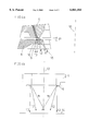
- FIG. 1 shows an annular illumination system and an optical element according to the invention
- FIG. 2a illustrates the light beams when emanating from the light fibers
- FIG. 2b represents the geometrical situation of the light beams without an optical element according to the present invention
- FIG. 3a shows the light beams emanating from the optical element when it engages the light emanating surfaces of the fibers
- FIG. 3b represents the geometrical situation of the light beams with an optical element according to the present invention which engages the light emanating surfaces of the fibers;
- FIG. 4a shows the light beams emanating from the optical element when it is in a distance to the light emanating surfaces of the fibers
- aFIG. 4b represents the geometrical situation of the light beams with an optical element according to the present invention which is in a distance to the light emanating surfaces of the fibers
- FIG. 5 is a graph of light flux versus working distance.
- annular illumination system is generally designated 1.
- This annular illumination system is arranged around the lens of a microscope not shown and serves for illuminating the object to be examined.
- the annular illumination system 1 is merely schematically illustrated in the figure wherein the left side shows the annular illumination system partly in cross-section while the right side depicts it in a lateral view.
- a fiber guide including fibers 5 into a cavity 2 of the annular illumination system 1.
- an annular gap 4 is provided into which the fibers 5 of the light guide run while being evenly distributed over the whole annular surface 3 of the gap.
- the light emanating surface of all fibers 5 is planely ground and polished in the plane of the annular surface 3.
- the gap 4 may have, for example, an average diameter of 56 mm and a constant width within a range of 0.5 to 0.75 mm.
- the numerical aperture of the fibers made of glass may be 0.57.
- An optical element 6 faces the gap 4 and the fibers 5 and is, preferably, formed as an ring-shaped or approximately toroidal, convex lens of plastic.
- This optical element 6 may be formed integrally with a holding ring 7 (or other adjustment device, such as a displaceable adjustment handle).
- the optical element 6 and the holding ring 7 form a structural unit rotatably supported on the peripheral wall of the annular illumination system, a guide pin 8 engaging a helical guiding groove 8'.
- three guide pins 8 are uniformly distributed over the periphery of the holding ring 7 in a manner not shown.
- rotating the optical element 6 will result in varying the distance between the optical element 6 and the light emanating surface of the fibers 5.
- the ring-shaped optical element 6 is co-axial to the dash-dotted axis of symmetry (designated 10 in FIG. 2a) of the microscope lens not shown.
- any other means for guiding the holding ring 7, particularly when moving in a direction parallel to the dash-dotted axis towards and from the light emanating surface 9, may be used, such as a groove parallel to this axis.
- FIG. 2a a detail is shown which illustrates that light emanating cone (aperture angle ⁇ ) is asymmetric with respect to the axis of symmetry 10 of the annular illumination system due to machining and providing a respective emanation surface 9 under an angle ⁇ .
- the emanation surface 9 itself is suitably orthogonal to the axis of symmetry 10.
- the light beams emanate under various angles ⁇ , the inner marginal beams, which are directed towards the axis of symmetry 10 being designated 11, the middle beams being designated 12 and the outer marginal beams, that extend almost parallel to the axis of symmetry 10, being designated 13.
- FIG. 2b shows the geometry of these light beams 11, 12 and 13 towards an object 14 to be illuminated. It may be seen that, with the distance shown between the object 14 and the annular illumination system 1, the inner marginal beams 11 do not illuminate the object 14 so that there is clearly a loss in light intensity.
- the optical element 6 of which only a portion is shown, is formed as a ring-shaped lens (consisting preferably of a single lens element, although there may be more) and has such a geometry that the light beams emanating under different angles ⁇ (as in FIG. 2a) pass through a course of zones 15 which are clearly optically effective to a different extent.
- the ring-shaped or toroidal lens is formed as a convex rotation symmetrical lens effective for those light beams 11 and 12 which are inclined to the axis of symmetry 10. The smaller the emanating angle ⁇ (see FIG. 2a) of the inclined light beams, the more these light beams 11, 12 are deviated towards a longer distance of the object to be illuminated, which results in a clearly increased light intensity at the object 14, as is shown in FIG. 3b.
- the optical element 6 has no or almost no diffractive power and is, preferably formed as a plane parallel plate.
- the optical element 6, described with reference to FIG. 1 is positioned in a distance 17 from the light emanating surface 9 as shown in FIG. 4a, the inclination to he axis of symmetry 10 of the light beams 11, 12 projected is changed in such a way that a deviation towards an even longer object distance is obtained, as is illustrated in FIG. 4b.
- the enlargement of the distance 17 has the effect that a larger diffractive power of the zone 15 becomes effective for beams which emanate under a small angle ⁇ (see FIG. 2a).
- the distance 17 is preferably variable between a zero-distance, as in FIG. 3a to a certain maximum distance which may be that of FIG. 4a depending on the pitch and length of the groove 8' (FIG. 1).
- the curvature of the lens element 6 and the pitch and length of the groove 8' may also be chosen in such a manner that the element 6 has a certain minimum distance from the light emanating surface 9 other than zero.
- the distance 17 By varying the distance 17, focusing conditions of the light beams, the size of the illuminated area and the homogeneity of light in the illuminated area can be adjusted. This is also possible with different working distances.
- the graph of FIG. 5 shows the gain in illumination intensity by the use of attaching the lens 6 according to the invention to the annular illumination system 1.
- the working distance d between the annular illumination system 1 and the object 14 is plotted on the abscissa in a range of 20 to 300 mm, and the light flux I is plotted on the ordinate at left.
- Curve Io illustrates the illumination intensity without using the attachment lens
- curve Ifok shows the illumination intensity achieved by the use of an attachment lens according to the invention focused to different working distances.
Landscapes
- Physics & Mathematics (AREA)
- Chemical & Material Sciences (AREA)
- Analytical Chemistry (AREA)
- General Physics & Mathematics (AREA)
- Optics & Photonics (AREA)
- Microscoopes, Condenser (AREA)
- Optical Couplings Of Light Guides (AREA)
- Lenses (AREA)
Applications Claiming Priority (2)
| Application Number | Priority Date | Filing Date | Title |
|---|---|---|---|
| AT1154/98 | 1998-07-02 | ||
| AT0115498A AT407305B (de) | 1998-07-02 | 1998-07-02 | Vorsatzoptik |
Publications (1)
| Publication Number | Publication Date |
|---|---|
| US6061184A true US6061184A (en) | 2000-05-09 |
Family
ID=3507788
Family Applications (1)
| Application Number | Title | Priority Date | Filing Date |
|---|---|---|---|
| US09/339,723 Expired - Lifetime US6061184A (en) | 1998-07-02 | 1999-06-24 | Attachment lens |
Country Status (5)
| Country | Link |
|---|---|
| US (1) | US6061184A (enExample) |
| EP (1) | EP0969304B1 (enExample) |
| JP (1) | JP2000081574A (enExample) |
| AT (1) | AT407305B (enExample) |
| DE (1) | DE59909293D1 (enExample) |
Cited By (2)
| Publication number | Priority date | Publication date | Assignee | Title |
|---|---|---|---|---|
| US20150043013A1 (en) * | 2012-05-07 | 2015-02-12 | Carl Zeiss Industrielle Messtechnik Gmbh | Illumination module for a coordinate measuring machine |
| US10371500B2 (en) | 2015-04-13 | 2019-08-06 | Carl Zeiss Industrielle Messtechnik Gmbh | Incident-light illumination for a variable working distance |
Families Citing this family (2)
| Publication number | Priority date | Publication date | Assignee | Title |
|---|---|---|---|---|
| DE102006018410A1 (de) | 2006-04-20 | 2007-10-25 | Carl Zeiss Microimaging Gmbh | Einrichtung zur Kontraststeigerung für Ringlichtbeleuchtungen |
| DE102013112186A1 (de) | 2013-11-06 | 2015-05-07 | Carl Zeiss Industrielle Messtechnik Gmbh | Verbessertes Beleuchtungsmodul für einen Metrologiesensor, insbesondere ein Koordinatenmessgerät |
Citations (4)
| Publication number | Priority date | Publication date | Assignee | Title |
|---|---|---|---|---|
| EP0019309A1 (en) * | 1979-04-11 | 1980-11-26 | Jean Louis Jeanne Chandesais | Ring lighting for the dark ground observation of a precious stone |
| DE8906859U1 (de) * | 1988-08-03 | 1989-07-13 | Jenoptik Jena Gmbh, Ddr 6900 Jena | Einrichtung zur Dunkelfeldauflichtbeleuchtung, insbesondere für Koordinatenmeßgeräte |
| DE4130698A1 (de) * | 1991-09-14 | 1993-03-18 | Vialog Visuelle Automations An | Beleuchtungsvorrichtung fuer mikroskopisch zu betrachtende objekte |
| US5329936A (en) * | 1991-02-04 | 1994-07-19 | Citation Medical Corporation | Portable arthroscope with periscope optics |
Family Cites Families (4)
| Publication number | Priority date | Publication date | Assignee | Title |
|---|---|---|---|---|
| DE1622989A1 (de) * | 1968-01-08 | 1971-01-07 | Reinert Guido Georg | Auflichtmikroskopobjektiv |
| US4729070A (en) * | 1986-05-12 | 1988-03-01 | David Chiu | Adjustable ring light |
| DE4016264A1 (de) * | 1990-05-19 | 1991-11-21 | Faseroptik Henning Gmbh & Co | Faseroptik-ringlicht |
| DE29621092U1 (de) * | 1996-12-05 | 1997-01-23 | Carl Zeiss Jena Gmbh, 07745 Jena | Anordnung zur Auflicht-Objektbeleuchtung |
-
1998
- 1998-07-02 AT AT0115498A patent/AT407305B/de not_active IP Right Cessation
-
1999
- 1999-06-12 EP EP99111477A patent/EP0969304B1/de not_active Expired - Lifetime
- 1999-06-12 DE DE59909293T patent/DE59909293D1/de not_active Expired - Lifetime
- 1999-06-24 US US09/339,723 patent/US6061184A/en not_active Expired - Lifetime
- 1999-06-29 JP JP11184190A patent/JP2000081574A/ja not_active Ceased
Patent Citations (4)
| Publication number | Priority date | Publication date | Assignee | Title |
|---|---|---|---|---|
| EP0019309A1 (en) * | 1979-04-11 | 1980-11-26 | Jean Louis Jeanne Chandesais | Ring lighting for the dark ground observation of a precious stone |
| DE8906859U1 (de) * | 1988-08-03 | 1989-07-13 | Jenoptik Jena Gmbh, Ddr 6900 Jena | Einrichtung zur Dunkelfeldauflichtbeleuchtung, insbesondere für Koordinatenmeßgeräte |
| US5329936A (en) * | 1991-02-04 | 1994-07-19 | Citation Medical Corporation | Portable arthroscope with periscope optics |
| DE4130698A1 (de) * | 1991-09-14 | 1993-03-18 | Vialog Visuelle Automations An | Beleuchtungsvorrichtung fuer mikroskopisch zu betrachtende objekte |
Non-Patent Citations (2)
| Title |
|---|
| Applied Optics, vol. 23, No. 16, Aug. 15, 1984, pp 2670/71, "Illuminator for dark field . . ." Douglas S. Goodman. |
| Applied Optics, vol. 23, No. 16, Aug. 15, 1984, pp 2670/71, Illuminator for dark field . . . Douglas S. Goodman. * |
Cited By (3)
| Publication number | Priority date | Publication date | Assignee | Title |
|---|---|---|---|---|
| US20150043013A1 (en) * | 2012-05-07 | 2015-02-12 | Carl Zeiss Industrielle Messtechnik Gmbh | Illumination module for a coordinate measuring machine |
| US9453718B2 (en) * | 2012-05-07 | 2016-09-27 | Carl Zeiss Industrielle Messtechnik Gmbh | Illumination module for a coordinate measuring machine |
| US10371500B2 (en) | 2015-04-13 | 2019-08-06 | Carl Zeiss Industrielle Messtechnik Gmbh | Incident-light illumination for a variable working distance |
Also Published As
| Publication number | Publication date |
|---|---|
| ATA115498A (de) | 2000-06-15 |
| EP0969304A3 (de) | 2000-02-23 |
| AT407305B (de) | 2001-02-26 |
| EP0969304A2 (de) | 2000-01-05 |
| EP0969304B1 (de) | 2004-04-28 |
| DE59909293D1 (de) | 2004-06-03 |
| JP2000081574A (ja) | 2000-03-21 |
Similar Documents
| Publication | Publication Date | Title |
|---|---|---|
| US4291938A (en) | Apparatus for dark field illumination | |
| US5642456A (en) | Light intensity attenuator for optical transmission systems | |
| US5775799A (en) | Lighting device incorporating a zoomable beamspreader | |
| JP3370612B2 (ja) | 光強度変換素子、コリメートレンズ、対物レンズ及び光学装置 | |
| US4961622A (en) | Optical coupler and refractive lamp | |
| US4626079A (en) | Dark field illumination apparatus for epi-illumination system | |
| US3278738A (en) | Light deflector | |
| US5820250A (en) | Dark field illuminator ringlight adaptor | |
| CA2139540A1 (en) | Compact surgical illumination system capable of dynamically adjusting the resulting field of illumination | |
| EP0385262A2 (de) | Beobachtungsgerät mit Auflicht-Beleuchtungseinrichtung | |
| JPS62502710A (ja) | 一定収束角及び可変サイズのスポツトビ−ムの照射装置 | |
| US4240738A (en) | Light mixing system for a photographic enlarger | |
| EP0472718B1 (en) | Optical system for lighting fixture | |
| CA1245487A (en) | Apparatus of projecting luminous lines on an object by a laser beam | |
| JP3722547B2 (ja) | 照明光学系 | |
| US4994945A (en) | Lamp system for operating theatres and the like | |
| JPS59211014A (ja) | 変倍観察装置 | |
| KR100500221B1 (ko) | 투사형 디스플레이용 분광 광선 균일화 장치 | |
| US20080088919A1 (en) | Illumination device for a microscope | |
| US6061184A (en) | Attachment lens | |
| CA2008529A1 (en) | Lamp system for operating theatres and the like | |
| US5485319A (en) | Medical device for lighting a treatment field | |
| US4160578A (en) | Annular reflector for microscope objective | |
| US20030156409A1 (en) | Variable incidence oblique illuminator device | |
| US5613768A (en) | Apparatus for generating parallel light using two arrayed mirrors |
Legal Events
| Date | Code | Title | Description |
|---|---|---|---|
| AS | Assignment |
Owner name: PHOTONIC OPTISCHE GERATE GES M.B.H. & CO. KG, AUST Free format text: ASSIGNMENT OF ASSIGNORS INTEREST;ASSIGNOR:ZEHETNER, HELMUT;REEL/FRAME:010488/0265 Effective date: 19991216 |
|
| STCF | Information on status: patent grant |
Free format text: PATENTED CASE |
|
| FPAY | Fee payment |
Year of fee payment: 4 |
|
| FPAY | Fee payment |
Year of fee payment: 8 |
|
| REMI | Maintenance fee reminder mailed | ||
| FPAY | Fee payment |
Year of fee payment: 12 |