US6052909A - Hand-held oval cutting device - Google Patents
Hand-held oval cutting device Download PDFInfo
- Publication number
- US6052909A US6052909A US09/140,264 US14026498A US6052909A US 6052909 A US6052909 A US 6052909A US 14026498 A US14026498 A US 14026498A US 6052909 A US6052909 A US 6052909A
- Authority
- US
- United States
- Prior art keywords
- plate
- fastener
- knob
- depression
- cutting
- Prior art date
- Legal status (The legal status is an assumption and is not a legal conclusion. Google has not performed a legal analysis and makes no representation as to the accuracy of the status listed.)
- Expired - Fee Related
Links
Images


Classifications
-
- B—PERFORMING OPERATIONS; TRANSPORTING
- B26—HAND CUTTING TOOLS; CUTTING; SEVERING
- B26B—HAND-HELD CUTTING TOOLS NOT OTHERWISE PROVIDED FOR
- B26B29/00—Guards or sheaths or guides for hand cutting tools; Arrangements for guiding hand cutting tools
- B26B29/06—Arrangements for guiding hand cutting tools
Definitions
- This invention relates to cutting devices, and more particularly to a device for cutting ovals of variable sizes in photographs, sheets, mats, and the like.
- Prior art hand-held elliptical cutting devices also typically include a large number of moving parts that require two-hand manipulation.
- one of the arms and/or hands of the user will invariably block another of the arms and/or hands since one hand is usually held stationary while the other hand moves in an elliptical pattern.
- This type of interference can produce results that are below expectations since the cutting operation must be stopped, the moving hand repositioned under the interfering arm, and the cutting operation restarted.
- Many variables are introduced into the cutting operation during hand repositioning, such as uneven or inconsistent pressure applied to the cutting device from one or both hands, leaning or inadvertent moving of the device, etc. Thus, these types of devices are difficult to manipulate and maintain accurate and consistent cuts.
- the hand-held device comprises a first member adapted for placement on the sheet material.
- the first member has a first pivot point that is movable along a first axis.
- a second member has a second pivot point that is movable along a second axis, preferably substantially perpendicular to the first axis.
- the first and said second members are operably connected to each other at the first and second pivot points.
- a knob is connected to one of the first and second pivot points, the knob being adapted for grasping by a user such that rotation of the knob about the one pivot point causes the second member to rotate and slide in an elliptical pattern with respect to the first member.
- a hand-held device for forming an elliptical shape in a sheet of material comprises a first plate member adapted for placement on the sheet material.
- the first plate member has a first pivot point that is movable along a first axis.
- a second plate member has a second pivot point that is preferably movable along a second axis substantially perpendicular to the first axis.
- the first and second plate members are operably connected to each other at the first and second pivot points.
- a forming member is operably connected to the second plate member for forming the elliptical shape in the sheet of material.
- the forming member may be a writing implement, scribing tool, cutting device, or the like.
- a knob may be connected to one of the first and second pivot points.
- the knob is adapted for grasping and rotation by a user. Rotation of the knob about the one pivot point causes the forming member to move in the elliptical path.
- a hand-held device for cutting an elliptical shape in a sheet of material comprises an elliptical base plate having major and minor axes.
- the base plate includes upper and lower surfaces with an elongate slot extending along one of the axes between the upper and lower surfaces.
- a channel is formed in the upper surface and extends along the other of the axes.
- a plurality of resilient feet are attached to the lower surface of the base plate for contacting the sheet of material.
- An adjusting plate has upper and lower surfaces with an elongate slot extending therebetween.
- the lower surface of the adjusting plate comprises at least one linear matrix of bores that extends generally parallel to the elongate slot of the adjusting plate.
- a spacer block is located between the base plate and the adjusting plate.
- the spacer block includes a registration pin that projects from an upper surface thereof for reception into one of the bores when the plates and block are connected together.
- An elongate fastener has a head portion and a shaft portion, with the shaft portion extending through the slot in the base plate, an aperture in the spacer block and the slot in the adjusting plate.
- the head portion of the fastener is adjacent the base plate lower surface.
- a knob is threaded onto a distal end of the shaft portion for holding the base plate, spacer block and adjusting plate together.
- the adjusting plate and spacer block are rotatable about a first movable pivot point defined by a longitudinal axis of the elongate fastener.
- the adjusting plate together with the spacer, elongate fastener and knob are also translatable along the slot in the base plate.
- a slider block is located in the channel of the base plate and is pivotally attached to the spacer block to define a second movable pivot point that is translatable along the channel.
- a blade holder is connected to an outer end portion of the adjusting plate for receiving a cutting blade.
- the blade holder has a lower end portion with a depression formed therein.
- the depression is shaped to receive a substantial portion of the cutting blade, with a depth of the depression being at least equal to a thickness of the cutting blade.
- First and second fasteners are mounted to the holder. Each of the fasteners has a head portion. The head portion of the first fastener is partially located in the depression such that a space for the cutting blade is formed between the head portion and a bottom surface of the depression. The head portion of the second fastener is entirely located in the depression such that the cutting blade can be securely held between the head portion of the second fastener and the bottom surface of the depression.
- the knob is of sufficient size to be grasped by the hand of a user and rotated about the elongate fastener. Rotation of the knob causes the adjusting plate to rotate about and translate with the first and second pivot points to thereby move the cutting blade along the elliptical path.
- the size of the elliptical path is adjustable by positioning at least one registration pin in a selected bore of the matrix of bores.
- FIG. 1 is a side elevational view of a hand-held oval cutting device according to the invention
- FIG. 2 is a rear elevational view of the hand-held oval cutting device
- FIG. 3 is an exploded side view of the hand-held oval cutting device
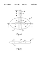
- FIG. 4 is a top plan view of a base plate and slider block according to the invention.
- FIG. 5 is a cross sectional view of the base plate taken along line 5--5 of FIG. 4;
- FIG. 6 is a top plan view of an adjusting plate according to the invention.
- FIG. 7 is a cross sectional view of the adjusting plate taken along line 7--7 of FIG. 6;
- FIG. 8 is a top plan view of a spacer block according to the invention.
- FIG. 9 is an enlarged rear elevational view of a blade holder according to the invention.
- FIG. 10 is a top plan view of the blade holder of FIG. 9;
- FIG. 11 is a top plan view of the hand-held oval cutting device at a first cutting position
- FIG. 12 is a top plan view of the hand-held oval cutting device at a second cutting position
- FIG. 13 is a top plan view of the hand-held oval cutting device at a third cutting position.
- FIG. 14 is a top plan view of the hand-held oval cutting device at a fourth cutting position.
- a hand-held oval cutting device 10 comprises a base plate 12 pivotally connected to a spacer block 14 and an adjusting plate 16, with a blade holder 18 fixedly connected to the adjusting plate 16.
- An elongate machine screw 20 or other suitable fastener has a head portion 54 and a threaded shaft portion 26.
- the shaft portion 26 extends through the base plate 12, the spacer block 14, and the adjusting plate 16.
- a knob 22 includes a lower stem portion 24 that receives an upper end portion of the threaded shaft 26 for holding the base plate, spacer block, and adjusting plate together.
- An upper handle portion 28 of the knob 22 is adapted to be grasped and manipulated by one hand of a user.
- the base plate 12 is preferably elliptical in shape.
- a slot 30 extends through the base plate 12 from an upper surface 32 to a lower surface 34 thereof.
- the slot 30 preferably lies along a major axis 36 of the ellipsoid.
- a channel 38 is formed in the upper surface 32 of the base plate 12 and preferably extends along a minor axis 40 of the ellipsoid, intersecting the slot 30.
- a slider block 42 is dimensioned to be slidably received in the channel 38 with a length "A" that is preferably longer than a width of the slot 30.
- An opening 44 extends through the slider block 42 and is adapted to pivotally receive a pivot pin 46 (FIG. 3) that projects downwardly from the spacer block 14.
- a plurality of resilient feet 48 are attached to the lower surface 34 of the base plate 12, preferably through an adhesive layer, but may alternatively be attached by suitable fasteners, ultrasonic welding, or other well-known means.
- the resilient feet are arranged so as to firmly grip the surface of a sheet material during cutting.
- the terms "forward,” “rearward,” “upper,” and “lower” and other directional terms are indicative of relative, not absolute orientations or positions.
- the cutting device is constructed of clear plastic material, with the exception of the knob 22 which may be constructed of nylon or the like.
- the spacer block 14 includes a threaded aperture 50 that receives the threads of the fastener 20 to mount the block 14 to the base plate 12.
- a bushing 52 is received in the slot 30 between the head 54 of the fastener 20 and a lower surface 56 of the block 14, and is dimensioned to slide freely in the slot 30.
- the shaft 26 of the fastener 20 extends through the bushing 52.
- the height of the bushing is slightly greater than the thickness of the base plate 12 such that the head 54 is slightly spaced from the lower surface 34 of the base plate to minimize friction during pivoting and sliding movements of the adjusting plate and spacer block with respect to the base plate.
- the pivot pin 46 is preferably installed in an aperture formed in the spacer block 14 through press fitting or other well-known means, and projects downwardly from the lower surface 56. As described previously, the pivot pin 46 extends through the slider block 42 and constrains movement of the slider block within the channel 38 when the spacer block is rotated with respect to the base plate.
- Two registration pins 58 project upwardly from an upper surface 60 of the spacer block 14 for a purpose to be described in greater detail below. As with the pivot pin 46, the registration pins 58 are preferably installed in apertures formed in the spacer block 14 through press fitting.
- a slot 62 extends through the adjusting plate 16 from an upper surface 64 to a lower surface 66 thereof.
- the slot 62 preferably lies along a longitudinal axis 68 of the plate 16.
- a pair of opposing channels 70 is formed in the lower surface 66 of the adjusting plate 16.
- the channels are preferably formed on either side of the slot 62 and extend parallel therewith.
- Each channel 70 comprises a linear array of intersecting bores 72, with each bore being sized to receive one of the registration pins 58.
- Apertures 74 extend through an end portion 76 of the adjusting plate 16 and are sized to receive threaded fasteners 78 (FIG. 3) for securing the blade holder 18 to the lower surface 66 of the adjusting plate 16.
- the blade holder 18 is preferably L-shaped with a first upright leg 80 and a second leg 82 that extends substantially perpendicular to the first leg. Bores 84 extend downwardly from an upper surface 86 of the second leg 82. When assembled, the bores 84 are in alignment with the apertures 74 of the aligning plate 16, and the fasteners 78 extend through the apertures 74 and thread into the bores 84.
- a depression 88 is formed in the rear surface 90 of the holder 18.
- the depression 88 has a lower side wall 89 and an upper side wall 91 that together define a depression area 93.
- the depression area 93 is shaped to receive a standard razor-type cutting blade 92 (shown in phantom line). Blades manufactured under the trade name X-ACTOTM, for example, would be suitable.
- the depth of the depression 88 is greater than or equal to the thickness of the blade 92 in order to shield as much of the blade as possible from a user.
- an upper aperture 94 and a pair of lower apertures 96 extend between the front surface 98 and rear surface 90 of the holder 18.
- a rivet 100 or other fastener with a head 102 is installed in each of the lower apertures 96 while a threaded fastener 104 with a head 106 is threaded in the upper aperture 94.
- a portion of each head 102 abuts the rear surface 90 while a remaining portion of each head extends into the depression area 93 to form a space between an inner depression surface 108 and the head 102. In this manner, a cutting end 110 of the blade 92 can be captured between the depression surface 108 and head 102 when installed.
- the fastener 104 is installed with the head located completely within the depression area 93. A mounting end 112 of the blade 92 can then be firmly held between the head 106 and the depression surface 108. When it is desirous to remove the blade 92 from the holder 18, it is a simple matter to loosen the threaded fastener 104 and slide the blade along the surface 108 until the cutting end 110 of the blade is clear of the heads 102. Installation of the blade can be accomplished in the reverse order. Once installed, a cutting tip 114 of the blade 92 extends a predetermined distance below a lower surface 116 of the holder 18 for cutting materials of a predetermined thickness. It will be understood of course, that the predetermined distance may be adjustable to accommodate different material thickness.
- the blade holder and blade extend substantially perpendicular from the adjusting member 16 to form a straight cut in a sheet of material, there may be some instances where it is desirous to cut a beveled surface.
- the blade holder and/or adjusting member may be modified to position the blade at an acute angle with respect to a surface of the sheet material to be cut.
- the oval cutting device 10 can be adjusted to cut different sizes of ovals by first loosening the knob 22, lifting the adjusting plate 16 until the registration pins 58 are clear of their respective bores 84, sliding the adjusting plate forward or rearward until the pins 58 are in alignment with a new set of bores, and then retightening the knob 22 with the adjusting plate in the new position. Since the fastener 20 is also threaded into the spacer block 14, the spacer block remains together with the base plate 12, although pivoting and sliding movement between the spacer block and base plate may occur.
- the cutting device is positioned in an initial cutting position on a sheet of material 118 with the resilient feet 48 in contact with an upper surface of the sheet.
- the base member 12 is preferably oval-shaped and includes an elliptically-shaped outer periphery 115 that is preferably substantially parallel to an oval 120 (shown in phantom line) to be cut.
- the shape of the base member 12 greatly facilitates initial placement and alignment of the cutting device 10 on the sheet of material to be cut.
- the adjusting block 16 can be adjusted to cut an oval 120 of a predetermined dimension, as previously described.
- the screw 20 is fixed with respect to the slot 62 midway between the ends of the slot 62 to define a medium size oval to be cut.
- the knob 22 is then grasped in one hand by a user and pressed downwardly to maintain the position of the device 10 on the sheet 118. Simultaneously, the knob is rotated in a clockwise direction as shown by arrow 122.
- the slider block 42 and pivot pin 46 move in a direction represented by arrow 124 from a central portion of the channel 38 of the base member 12 to a lower end of the channel.
- the screw 20 slides in the slot 32 of the base member 12 in a direction represented by arrow 126 from a first end of the slot 32 to a central portion of the slot 32, and simultaneously rotates in the direction 122.
- the mutual position of the screw 20 and slot 62 do not change during movement since they are fixed together by the knob 22, as is evident from FIGS. 12-14.
- the screw 22 functions as a first movable pivot point for the adjusting plate 16 (and attached blade holder 18 and blade 92). Sliding movement of the pivot pin 46 in the channel 38 and simultaneous rotation of the adjusting plate 16 about the pivot pin 46 defines a second movable pivot point about the pivot pin 46.
- the cutting tip 114 of the blade 92 is preferably located at the intersection 128 of the longitudinal axis 68 and the cutting path 120.
- the distance between the first and second pivot points is maintained during the elliptical movement.
- the distance between the pivot points and the cutting tip 114 can be adjusted when not cutting by loosening the knob 22 and locating the registration pins 58 in a different set of bores 72, as previously described.
- the blade 92 can be set for counter clockwise rotation if desired, which is preferable for left-handed use.
- the cutting device 10 is intended primarily for cutting ovals in photographs, cardboard sheets and the like, the blade holder can be adapted to receive other cutting implements for ceramic, glass, wood, etc., or can be modified to receive standard drawing implements.
Landscapes
- Life Sciences & Earth Sciences (AREA)
- Forests & Forestry (AREA)
- Engineering & Computer Science (AREA)
- Mechanical Engineering (AREA)
- Details Of Cutting Devices (AREA)
Abstract
Description
Claims (30)
Priority Applications (8)
| Application Number | Priority Date | Filing Date | Title |
|---|---|---|---|
| US09/140,264 US6052909A (en) | 1998-08-26 | 1998-08-26 | Hand-held oval cutting device |
| PCT/US1999/019389 WO2000012275A1 (en) | 1998-08-26 | 1999-08-24 | Hand-held oval cutting device |
| MXPA01002064A MXPA01002064A (en) | 1998-08-26 | 1999-08-24 | Hand-held oval cutting device. |
| CA002341702A CA2341702A1 (en) | 1998-08-26 | 1999-08-24 | Hand-held oval cutting device |
| AU59003/99A AU5900399A (en) | 1998-08-26 | 1999-08-24 | Hand-held oval cutting device |
| US09/536,920 US6484406B1 (en) | 1998-08-26 | 2000-03-28 | Hand-held cutting devices |
| US10/262,155 US6668461B2 (en) | 1998-08-26 | 2002-10-01 | Hand-held cutting device |
| US10/661,963 US7010860B2 (en) | 1998-08-26 | 2003-09-12 | Hand-held cutting device |
Applications Claiming Priority (1)
| Application Number | Priority Date | Filing Date | Title |
|---|---|---|---|
| US09/140,264 US6052909A (en) | 1998-08-26 | 1998-08-26 | Hand-held oval cutting device |
Related Child Applications (2)
| Application Number | Title | Priority Date | Filing Date |
|---|---|---|---|
| US09/536,920 Continuation-In-Part US6484406B1 (en) | 1998-08-26 | 2000-03-28 | Hand-held cutting devices |
| US09/536,920 Division US6484406B1 (en) | 1998-08-26 | 2000-03-28 | Hand-held cutting devices |
Publications (1)
| Publication Number | Publication Date |
|---|---|
| US6052909A true US6052909A (en) | 2000-04-25 |
Family
ID=22490473
Family Applications (4)
| Application Number | Title | Priority Date | Filing Date |
|---|---|---|---|
| US09/140,264 Expired - Fee Related US6052909A (en) | 1998-08-26 | 1998-08-26 | Hand-held oval cutting device |
| US09/536,920 Expired - Fee Related US6484406B1 (en) | 1998-08-26 | 2000-03-28 | Hand-held cutting devices |
| US10/262,155 Expired - Fee Related US6668461B2 (en) | 1998-08-26 | 2002-10-01 | Hand-held cutting device |
| US10/661,963 Expired - Fee Related US7010860B2 (en) | 1998-08-26 | 2003-09-12 | Hand-held cutting device |
Family Applications After (3)
| Application Number | Title | Priority Date | Filing Date |
|---|---|---|---|
| US09/536,920 Expired - Fee Related US6484406B1 (en) | 1998-08-26 | 2000-03-28 | Hand-held cutting devices |
| US10/262,155 Expired - Fee Related US6668461B2 (en) | 1998-08-26 | 2002-10-01 | Hand-held cutting device |
| US10/661,963 Expired - Fee Related US7010860B2 (en) | 1998-08-26 | 2003-09-12 | Hand-held cutting device |
Country Status (5)
| Country | Link |
|---|---|
| US (4) | US6052909A (en) |
| AU (1) | AU5900399A (en) |
| CA (1) | CA2341702A1 (en) |
| MX (1) | MXPA01002064A (en) |
| WO (1) | WO2000012275A1 (en) |
Cited By (41)
| Publication number | Priority date | Publication date | Assignee | Title |
|---|---|---|---|---|
| US6158133A (en) * | 1998-12-23 | 2000-12-12 | Fiskars Inc. | Oval cutter |
| US20010009123A1 (en) * | 1999-05-12 | 2001-07-26 | Carmen Lira-Nunez | Guided cutting system |
| US6484406B1 (en) | 1998-08-26 | 2002-11-26 | Alterra Holdings Corporation | Hand-held cutting devices |
| US6582445B1 (en) * | 1998-03-11 | 2003-06-24 | Visx, Incorporated | Trephine for lamellar keratectomy |
| US20030120276A1 (en) * | 2000-05-01 | 2003-06-26 | Tallarida Steven J. | System and method for joint resurface repair |
| US20040015170A1 (en) * | 2000-05-01 | 2004-01-22 | Tallarida Steven J. | System and method for joint resurface repair |
| US20060085006A1 (en) * | 2002-12-03 | 2006-04-20 | Ek Steven W | System and method for retrograde procedure |
| US20070005143A1 (en) * | 2004-11-22 | 2007-01-04 | Ek Steven W | Articular surface implant and delivery system |
| US20080195113A1 (en) * | 2007-02-14 | 2008-08-14 | Arthrosurface Incorporated | Bone Cement Delivery Device |
| US7618462B2 (en) | 2000-05-01 | 2009-11-17 | Arthrosurface Incorporated | System and method for joint resurface repair |
| US7678151B2 (en) | 2000-05-01 | 2010-03-16 | Ek Steven W | System and method for joint resurface repair |
| US7713305B2 (en) | 2000-05-01 | 2010-05-11 | Arthrosurface, Inc. | Articular surface implant |
| US20110011290A1 (en) * | 2009-07-20 | 2011-01-20 | Quickutz, Inc. | Systems and methods applying a design on a medium |
| US7896883B2 (en) | 2000-05-01 | 2011-03-01 | Arthrosurface, Inc. | Bone resurfacing system and method |
| US7896885B2 (en) | 2002-12-03 | 2011-03-01 | Arthrosurface Inc. | Retrograde delivery of resurfacing devices |
| US7914545B2 (en) | 2002-12-03 | 2011-03-29 | Arthrosurface, Inc | System and method for retrograde procedure |
| US7951163B2 (en) | 2003-11-20 | 2011-05-31 | Arthrosurface, Inc. | Retrograde excision system and apparatus |
| US8177841B2 (en) | 2000-05-01 | 2012-05-15 | Arthrosurface Inc. | System and method for joint resurface repair |
| US8361159B2 (en) | 2002-12-03 | 2013-01-29 | Arthrosurface, Inc. | System for articular surface replacement |
| US8388624B2 (en) | 2003-02-24 | 2013-03-05 | Arthrosurface Incorporated | Trochlear resurfacing system and method |
| US8523872B2 (en) | 2002-12-03 | 2013-09-03 | Arthrosurface Incorporated | Tibial resurfacing system |
| CN103802173A (en) * | 2012-11-13 | 2014-05-21 | 吉生机械股份有限公司 | Axial adjustment device |
| US9066716B2 (en) | 2011-03-30 | 2015-06-30 | Arthrosurface Incorporated | Suture coil and suture sheath for tissue repair |
| US9283076B2 (en) | 2009-04-17 | 2016-03-15 | Arthrosurface Incorporated | Glenoid resurfacing system and method |
| US9358029B2 (en) | 2006-12-11 | 2016-06-07 | Arthrosurface Incorporated | Retrograde resection apparatus and method |
| USD763055S1 (en) | 2015-05-29 | 2016-08-09 | Fiskars Brands, Inc. | Fabric cutter |
| US9468448B2 (en) | 2012-07-03 | 2016-10-18 | Arthrosurface Incorporated | System and method for joint resurfacing and repair |
| US9492200B2 (en) | 2013-04-16 | 2016-11-15 | Arthrosurface Incorporated | Suture system and method |
| US9662126B2 (en) | 2009-04-17 | 2017-05-30 | Arthrosurface Incorporated | Glenoid resurfacing system and method |
| US20170274550A1 (en) * | 2016-03-22 | 2017-09-28 | Jonathan Potter, JR. | Circle Cutting System |
| US9861492B2 (en) | 2014-03-07 | 2018-01-09 | Arthrosurface Incorporated | Anchor for an implant assembly |
| US10035277B2 (en) | 2015-05-18 | 2018-07-31 | Fiskars Brands, Inc. | Apparatus and system for cutting a pattern in a sheet material |
| USD871886S1 (en) | 2017-11-02 | 2020-01-07 | Fiskars Finland Oy Ab | Shape cutter tool |
| US10624748B2 (en) | 2014-03-07 | 2020-04-21 | Arthrosurface Incorporated | System and method for repairing articular surfaces |
| US10624752B2 (en) | 2006-07-17 | 2020-04-21 | Arthrosurface Incorporated | Tibial resurfacing system and method |
| US10945743B2 (en) | 2009-04-17 | 2021-03-16 | Arthrosurface Incorporated | Glenoid repair system and methods of use thereof |
| US11160663B2 (en) | 2017-08-04 | 2021-11-02 | Arthrosurface Incorporated | Multicomponent articular surface implant |
| US11478358B2 (en) | 2019-03-12 | 2022-10-25 | Arthrosurface Incorporated | Humeral and glenoid articular surface implant systems and methods |
| US11607319B2 (en) | 2014-03-07 | 2023-03-21 | Arthrosurface Incorporated | System and method for repairing articular surfaces |
| US11712276B2 (en) | 2011-12-22 | 2023-08-01 | Arthrosurface Incorporated | System and method for bone fixation |
| US20240416542A1 (en) * | 2023-06-18 | 2024-12-19 | Jacob LaRocca | Handheld Cutting Device and System for Cutting Sheet Goods |
Families Citing this family (6)
| Publication number | Priority date | Publication date | Assignee | Title |
|---|---|---|---|---|
| TW512093B (en) * | 2002-03-28 | 2002-12-01 | Primax Electronics Ltd | Cutting apparatus |
| DE102006009178A1 (en) * | 2005-02-26 | 2006-09-07 | Schulte, Günter | Jig for cutting holes in roof lining has a sloping support held onto the outside of the roof and with a guide edge for a cutting tool |
| US8030891B2 (en) * | 2008-04-10 | 2011-10-04 | Smiths Medical Asd, Inc. | Ambulatory medical device with electrical isolation from connected peripheral device |
| USD613573S1 (en) * | 2009-04-10 | 2010-04-13 | Stephen Latta | Straight line cutter |
| US8715252B2 (en) * | 2012-09-14 | 2014-05-06 | Richard Dale Wayne Connor | Apparatus for applying roll-on and rub-on medications |
| US9073163B2 (en) * | 2012-11-15 | 2015-07-07 | Gison Machinery Co., Ltd. | Elliptically moving mechanism |
Citations (15)
| Publication number | Priority date | Publication date | Assignee | Title |
|---|---|---|---|---|
| US658710A (en) * | 1900-03-06 | 1900-09-25 | Torbett Forker M | Apparatus for cutting ovals from cardboard. |
| US697997A (en) * | 1901-07-12 | 1902-04-22 | Phillipp Drinkaus | Machine for cutting picture-mats. |
| US1007910A (en) * | 1910-10-27 | 1911-11-07 | Frank J Baker | Ellipsograph-machine. |
| US3562915A (en) * | 1968-05-07 | 1971-02-16 | Ellipstruments Ltd | Device for drawing elliptical paths |
| US3621574A (en) * | 1970-06-30 | 1971-11-23 | Gerald F Yanke | Photographic print circle cutter |
| US3834028A (en) * | 1972-09-29 | 1974-09-10 | J Okada | Apparatus to draw an oval |
| USD243117S (en) | 1975-05-30 | 1977-01-18 | Gene Green Associates, Inc. | Device for cutting picture frame mat boards |
| US4112793A (en) * | 1977-04-06 | 1978-09-12 | Donald Cameron Pierce | Device for cutting ovals in mats or glass sheets |
| US4244106A (en) * | 1979-05-29 | 1981-01-13 | Pierce Donald C | Device for describing an ellipse |
| US4567927A (en) * | 1982-09-30 | 1986-02-04 | Plamann Kenneth O | Apparatus for automatically forming ovals |
| US5058282A (en) * | 1991-04-08 | 1991-10-22 | Coll Albert G | Ellipsograph |
| US5099727A (en) * | 1989-07-14 | 1992-03-31 | The Fletcher-Terry Company | Mechanism and method for circumscribing oval shapes |
| US5189800A (en) * | 1989-05-08 | 1993-03-02 | Shiro Morita | Device for drawing elliptical curves |
| US5233748A (en) * | 1991-01-30 | 1993-08-10 | Curtis Logan | Adjustable oval mat cutter |
| US5526573A (en) * | 1993-09-10 | 1996-06-18 | The Fletcher-Terry Company | Device for circumscribing circles and ellipses |
Family Cites Families (135)
| Publication number | Priority date | Publication date | Assignee | Title |
|---|---|---|---|---|
| US386619A (en) | 1888-07-24 | wilson | ||
| US494864A (en) | 1893-04-04 | Metal-cutting machine | ||
| US517522A (en) | 1894-04-03 | Ellipsograph | ||
| US179039A (en) * | 1876-06-20 | Improvement in machines for cutting ovals | ||
| US572320A (en) | 1896-12-01 | Cutter for bevel-cards | ||
| US922819A (en) * | 1909-05-25 | Teodor Sosnowski | Burial-casket. | |
| DE81840C (en) | ||||
| US1326260A (en) | 1919-12-30 | Pie-trimmer | ||
| US660211A (en) | 1900-02-02 | 1900-10-23 | Carl C Durkel | Mat-cutter. |
| US658711A (en) | 1900-03-06 | 1900-09-25 | Torbett Forker M | Apparatus for cutting ovals from cardboard. |
| US705576A (en) | 1901-10-16 | 1902-07-29 | William H Forker | Oval-cutting machine. |
| US701828A (en) | 1901-11-04 | 1902-06-10 | John E Macdonald | Mat-cutter. |
| US742047A (en) | 1902-12-26 | 1903-10-20 | Friedrich Moehle | Marking instrument. |
| US973047A (en) | 1909-02-06 | 1910-10-18 | Theodore Jeter | Ellipsograph. |
| US1010292A (en) | 1911-02-18 | 1911-11-28 | Arthur L Mckinstry | Drawing instrument. |
| US1031780A (en) | 1911-08-25 | 1912-07-09 | Charles C Fine | Ellipsograph. |
| US1391530A (en) | 1919-07-01 | 1921-09-20 | Ramon J Bustillo Y Diego | Drafting appliance or equipment |
| US1470168A (en) | 1921-10-03 | 1923-10-09 | Hans H Jepsen | Scribing instrument |
| US1614772A (en) | 1925-11-25 | 1927-01-18 | Bambini Aurelio | Knife guard |
| US1837912A (en) | 1929-07-11 | 1931-12-22 | Robert E Mann | Ellipsograph |
| US1806484A (en) | 1930-05-02 | 1931-05-19 | Michaud Oscar | Knife for cutting shoes |
| US2215216A (en) | 1936-12-14 | 1940-09-17 | Joseph A Gits | Cutting implement |
| US2494557A (en) | 1944-05-16 | 1950-01-17 | Haden R Irick | Adjustable ellipse compass |
| US2458208A (en) | 1944-12-02 | 1949-01-04 | Ruger John | Scribing instrument |
| US2512786A (en) | 1945-12-18 | 1950-06-27 | Borg Kenneth | Drafting device |
| US2790240A (en) * | 1954-02-12 | 1957-04-30 | Silverstein Bernard | Drafting instrument |
| US2908972A (en) | 1956-07-31 | 1959-10-20 | Nitenson Edward | Artist's knife |
| US2872732A (en) | 1957-10-04 | 1959-02-10 | John B Arrowood | Lawn edger |
| US2925655A (en) | 1958-11-18 | 1960-02-23 | Beek Gerd W De | Ellipsograph |
| US3060779A (en) | 1960-05-31 | 1962-10-30 | Patrick M Taft | Cutting apparatus |
| US3032893A (en) | 1961-02-07 | 1962-05-08 | Debeh Ali | Educational toy |
| US3165130A (en) | 1961-02-21 | 1965-01-12 | Vestal O Sanders | Machine for cutting elliptical shapes |
| DE1265398B (en) | 1963-04-27 | 1968-04-04 | Schickedanz & Co | Device for cutting molded parts from a foam block |
| JPS484123Y1 (en) | 1968-11-06 | 1973-02-01 | ||
| US3576148A (en) | 1969-06-24 | 1971-04-27 | Bendix Corp | Strip-map-preparation device including a cutter and work-holder combination |
| JPS4719474Y1 (en) | 1970-04-01 | 1972-07-03 | ||
| JPS518152Y1 (en) | 1970-05-07 | 1976-03-04 | ||
| JPS5023336Y1 (en) | 1970-06-03 | 1975-07-14 | ||
| JPS5520094B2 (en) | 1971-11-20 | 1980-05-30 | ||
| US3867636A (en) | 1972-05-29 | 1975-02-18 | Morita Mfg | Apparatus for taking a continuous x-ray picture of the dental arch |
| DE2237396C2 (en) | 1972-07-29 | 1974-07-18 | Gebrueder Haff Gmbh, 8962 Pfronten | Ellipse drawing device |
| US3787968A (en) | 1972-09-15 | 1974-01-29 | Minnesota Mining & Mfg | Segment cutter |
| US3845676A (en) | 1973-06-05 | 1974-11-05 | D Pierce | Device for cutting ovals in mats or glass sheets |
| US3820245A (en) | 1973-06-26 | 1974-06-28 | D Yozzo | Drawing projector for reproducing curves |
| JPS5023336A (en) | 1973-07-04 | 1975-03-13 | ||
| JPS518152A (en) | 1974-07-10 | 1976-01-22 | Koike Sanso Kogyo Kk | Daensetsudansochi |
| DE2511081C2 (en) | 1975-03-13 | 1985-03-21 | Max Mayer Maschinenbau GmbH, 7914 Pfuhl | Slotting or mortising machine |
| DE2522188C3 (en) | 1975-05-17 | 1978-11-30 | Carl Braun Camera-Werk, 8500 Nuernberg | Device for eroding conical bores |
| SU547362A1 (en) | 1975-07-11 | 1977-02-25 | Ленинградский институт текстильной и легкой промышленности им.С.М.Кирова | Machine for the manufacture of filters from tubular synthetic materials |
| JPS5438466Y2 (en) | 1975-09-29 | 1979-11-15 | ||
| US4048724A (en) | 1976-04-12 | 1977-09-20 | Keuver Paul H | Ellipsograph |
| DE2621687A1 (en) | 1976-05-15 | 1977-12-01 | Bayerische Metallwarenfabrik M | Circular shape cutting tool - has rotating blades mounted in cylindrical hood to give clean cut to photos etc. for mounting in circular frame |
| GB1540240A (en) | 1976-08-10 | 1979-02-07 | Lockwood R | Cutter for cutting out profiles from sheet material |
| US4057898A (en) | 1976-08-16 | 1977-11-15 | Piosky Dennis E | Repair template for carpets or the like |
| IT1101888B (en) | 1977-02-21 | 1985-10-07 | Hoeckenreiner August | Glass cutter for cutting ellipses - consists of a cutter tool attached to a rule guide in a cross slide with slide guides |
| AT368109B (en) | 1977-02-21 | 1982-09-10 | Hoeckenreiner August | GLASS CUTTING DEVICE FOR CUTTING OUT ELLIPTICAL GLASS PLATES |
| JPS53119132U (en) | 1977-02-28 | 1978-09-21 | ||
| JPS53124391U (en) | 1977-03-10 | 1978-10-03 | ||
| JPS53119132A (en) | 1977-03-23 | 1978-10-18 | Kouichi Yokojima | Elliptical compass utilizing long and short axes of ellipse in difference |
| SU742397A1 (en) | 1977-06-02 | 1980-06-25 | За витель 54) УСТРОЙСТВО ДЛЯ БЕСКОПИРНОГО НАНЕСЕНИЯ ЭЛЛИПСНЫХ ЛИНИЙ НА ПЛОСКИЕ ЗАГОТОВКИ Изобретение относитс к устройствам дл нанесени эллипсных линий на плоские заготовки и предназначено дл нанесени линий реза на листовое стекло. Известно устройство дл нанесени эллипсов на плоскость 1. Это устройс | Device for formerless drawing of ellipse lines on flat piecies |
| SU640788A1 (en) | 1977-07-11 | 1979-01-05 | Ленинградский Ордена Ленина Политехнический Институт Им. М.И.Калинина | Die for punching round holes in thin-sheet stock |
| JPS587859B2 (en) | 1977-08-30 | 1983-02-12 | 酒井 一義 | Elliptical motion mechanism |
| JPS5460028U (en) | 1977-09-30 | 1979-04-25 | ||
| JPS5460028A (en) | 1977-10-20 | 1979-05-15 | Kazuyoshi Sakai | Elliptical drawing instrument |
| US4176452A (en) | 1977-12-16 | 1979-12-04 | Frameworks, Inc. | Picture frame mat opening cutter |
| DE2815383A1 (en) | 1978-04-10 | 1979-10-18 | Martin Eberlein | Milk carton piercing tool - has point with blade forming opening for tight fitting drinking straw |
| US4148144A (en) | 1978-05-04 | 1979-04-10 | Ron L. Norman | Oval compass |
| FR2441468A1 (en) | 1978-11-16 | 1980-06-13 | Martin Rene | Office punch with U=shaped hand lever - cuts four holes in leaf edge with inner holes oval and has waste box in moulded plastics body |
| JPS55146800U (en) | 1979-04-10 | 1980-10-22 | ||
| JPS55146800A (en) | 1979-05-02 | 1980-11-15 | Yoshio Nemoto | Elliptic drafting machine |
| JPS5520094A (en) | 1979-07-09 | 1980-02-13 | Taiko Denki Seisakusho:Kk | Assembling method of dial main spring |
| US4233736A (en) | 1979-11-19 | 1980-11-18 | Framework, Inc. | Pressure sensitive picture frame mat opening cutter |
| JPS6132800Y2 (en) | 1980-05-01 | 1986-09-24 | ||
| GB2075405A (en) | 1980-05-08 | 1981-11-18 | Frameworks Inc | Picture frame mat opening cutter |
| US4306598A (en) | 1980-06-26 | 1981-12-22 | The Singer Company | Ellipse cutting machine |
| US4407074A (en) | 1980-06-27 | 1983-10-04 | Ledbetter Buford B | Apparatus for cutting and/or scribing circles and ovals |
| SU946815A1 (en) | 1980-08-15 | 1982-07-30 | Предприятие П/Я В-8808 | Cutter |
| SU992439A1 (en) | 1980-10-29 | 1983-01-30 | Одесский филиал Всесоюзного научно-исследовательского и проектно-конструкторского института стекольного машиностроения | Method for machining glass sheet blank |
| DE3235823A1 (en) | 1981-09-30 | 1983-05-05 | CIBA-GEIGY AG, 4002 Basel | Cutting device for cutting web material into pieces |
| JPS6053592B2 (en) | 1981-11-10 | 1985-11-26 | 東洋製罐株式会社 | Mushroom extract manufacturing method |
| JPS58172240U (en) | 1982-05-10 | 1983-11-17 | 三菱電機株式会社 | Vehicle-mounted medium wave receiver |
| US4426781A (en) | 1982-05-27 | 1984-01-24 | Badge A. Minit Ltd. | Cutter for making paper discs |
| US4445275A (en) | 1982-06-07 | 1984-05-01 | David Dubrow | Drawing assembly |
| US4527332A (en) | 1982-11-30 | 1985-07-09 | Takaaki Aoki | Handy scissors |
| JPS59208830A (en) | 1983-05-13 | 1984-11-27 | Hitachi Ltd | Ion beam processing method and device |
| CA1231104A (en) | 1983-08-08 | 1988-01-05 | Eduard P. Kieffer | Process for the preparation of an aromatic hydrocarbon mixture |
| JPS6132800A (en) | 1984-07-26 | 1986-02-15 | 中務 美知雄 | Ellipse drawing rule |
| JPS6183987A (en) | 1984-10-01 | 1986-04-28 | Hitachi Medical Corp | Image data measuring control circuit |
| JPS6183987U (en) | 1984-11-06 | 1986-06-03 | ||
| JPS61226297A (en) | 1985-03-28 | 1986-10-08 | 安田 寛明 | Method and device for cutting ellipse |
| SU1282987A2 (en) | 1985-07-29 | 1987-01-15 | Предприятие П/Я В-2969 | Blade |
| US4624057A (en) | 1985-08-06 | 1986-11-25 | Hursey William A | Method and template for circle layouts |
| JPS6260699A (en) | 1985-09-10 | 1987-03-17 | 安田 寛明 | Elliptic trammel |
| US4649647A (en) | 1985-10-21 | 1987-03-17 | Kaulfuss Herbert E | Hand cutting tool |
| BE903666A (en) | 1985-11-19 | 1986-03-14 | Benit Claude | Cutting tool with controllable cutting depth - has handle with round or elliptical blade which can rotate or be locked in any position by sliding catch in handle |
| US4691604A (en) | 1986-04-25 | 1987-09-08 | Peerless Machine & Tool Corporation | Anti-jamming die |
| US4782730A (en) | 1986-11-26 | 1988-11-08 | John Picone | Straddling gasket cutter |
| FR2612113B3 (en) | 1987-03-12 | 1989-06-16 | Portner Paul | DEVICE FOR CUTTING SHAPES: ELLIPTICAL, OVAL, ROUND, TRIANGULAR, SQUARE AND RECTANGULAR WITH ENGLISH BEVELS (45O) IN SOFT MATERIALS |
| US4773798A (en) | 1987-08-05 | 1988-09-27 | The General Industries Company | Portable washer cutters |
| JPH01106296A (en) | 1987-10-20 | 1989-04-24 | Masahide Umezawa | Preaid card and distribution managing system thereby |
| US4790222A (en) | 1987-10-29 | 1988-12-13 | Morgan Carey C | Apparatus for cutting various forms out of a picture frame mat or the like |
| DE3837449A1 (en) | 1987-11-11 | 1989-05-24 | Josef Koch | Device for kinematically cutting, bending and milling oval or circular shapes |
| US4858322A (en) | 1988-02-09 | 1989-08-22 | Benjamin Kluga | Circle cutter employing base, swivel handle, and pivot bar with adjustable knife |
| JPH0624836Y2 (en) | 1988-07-07 | 1994-06-29 | 邦男 諸角 | Engraving device for making cutout masks |
| JP2552913B2 (en) | 1989-05-08 | 1996-11-13 | 司郎 森田 | Oval drafter |
| US5014584A (en) | 1989-07-14 | 1991-05-14 | The Fletcher-Terry Company | Machine and method for cutting oval shapes |
| DE3923785A1 (en) | 1989-07-18 | 1991-01-31 | Wangner Gmbh Co Kg Hermann | Patching hole in thermoplastic fabric in paper-making machine - by cutting elliptical hole, spot-welding overlapping patch, and pressing while heating ultrasonically |
| JPH0688478B2 (en) | 1989-09-18 | 1994-11-09 | 正二 国頭 | Ellipse plotter |
| JPH0727991Y2 (en) | 1990-02-02 | 1995-06-28 | 株式会社関水金属 | Stretching and swinging mechanism of a densely coupled coupler for railway model |
| JP3047044B2 (en) | 1990-02-22 | 2000-05-29 | 孝信 辻本 | Elliptical compass |
| GB2242147B (en) | 1990-03-22 | 1993-07-28 | Skf Gmbh | A device for forming pockets in cages |
| JPH0780390B2 (en) | 1990-10-29 | 1995-08-30 | 善人 池田 | Oval drafter |
| US5123170A (en) | 1991-02-14 | 1992-06-23 | Enrique Castaneda Mori | Ellipsograph as a drafting tool |
| US5253421A (en) * | 1991-10-31 | 1993-10-19 | Ake Landmark | Circle drawing kit apparatus |
| RU2038926C1 (en) | 1992-06-30 | 1995-07-09 | Центральный научно-исследовательский институт технологии судостроения | Device for machining intricate surfaces of parts |
| JPH0688478A (en) | 1992-09-09 | 1994-03-29 | Fujita Corp | Automatic control device for digging speed of shield machine |
| JPH06262586A (en) | 1993-03-16 | 1994-09-20 | Karl Jimuki Kk | Paper cutting machine |
| RU2066599C1 (en) | 1993-03-31 | 1996-09-20 | Хованов Николай Николаевич | Device for machining oval hole of tubular item |
| US5322001A (en) | 1993-05-28 | 1994-06-21 | Fiskars Oy Ab | Paper cutter with circular blades |
| JPH0780390A (en) | 1993-09-10 | 1995-03-28 | Nippon Steel Corp | Light pressure coating method with roll coater |
| JPH0890988A (en) | 1994-09-27 | 1996-04-09 | Mai Works:Kk | Elliptic trammel |
| US5555631A (en) | 1995-01-17 | 1996-09-17 | Houston; Daniel J. | Ellipse Scribe |
| GB2297526A (en) | 1995-02-03 | 1996-08-07 | Christopher John Longridge | Pen holder for an oval mat cutter |
| JP3426395B2 (en) | 1995-03-23 | 2003-07-14 | 本田技研工業株式会社 | Oval generating tool |
| US5802942A (en) | 1995-10-10 | 1998-09-08 | Fiskars Inc. | Paper trimmer |
| DE19617688A1 (en) | 1996-05-03 | 1997-11-13 | Juergen Kara | Method and stripping tool for stripping punch waste in the production of blanks from a sheet |
| JPH09300274A (en) | 1996-05-17 | 1997-11-25 | Hideo Kodera | Sheet cutting device |
| RU2112630C1 (en) | 1996-05-21 | 1998-06-10 | Петр Артемьевич Антипов | Method for making parts with elliptic contours by cutting |
| JPH1035182A (en) | 1996-07-17 | 1998-02-10 | Takanobu Tsujimoto | Elliptical compass |
| CN1209394A (en) | 1997-08-26 | 1999-03-03 | 迟宗杰 | Ellipse drawing instrument |
| CA2250561A1 (en) | 1998-01-30 | 1999-07-30 | Randall J. Urness | Cutter and marker of shapes and circles |
| DE19819915A1 (en) | 1998-05-05 | 1999-11-11 | Reddig Gmbh | Laying knife |
| JP4268246B2 (en) | 1998-08-12 | 2009-05-27 | Towa株式会社 | Elliptical vibration cutting machine |
| US6052909A (en) * | 1998-08-26 | 2000-04-25 | Gardner; Mark T. | Hand-held oval cutting device |
| US6158133A (en) | 1998-12-23 | 2000-12-12 | Fiskars Inc. | Oval cutter |
-
1998
- 1998-08-26 US US09/140,264 patent/US6052909A/en not_active Expired - Fee Related
-
1999
- 1999-08-24 CA CA002341702A patent/CA2341702A1/en not_active Abandoned
- 1999-08-24 WO PCT/US1999/019389 patent/WO2000012275A1/en not_active Ceased
- 1999-08-24 AU AU59003/99A patent/AU5900399A/en not_active Abandoned
- 1999-08-24 MX MXPA01002064A patent/MXPA01002064A/en not_active Application Discontinuation
-
2000
- 2000-03-28 US US09/536,920 patent/US6484406B1/en not_active Expired - Fee Related
-
2002
- 2002-10-01 US US10/262,155 patent/US6668461B2/en not_active Expired - Fee Related
-
2003
- 2003-09-12 US US10/661,963 patent/US7010860B2/en not_active Expired - Fee Related
Patent Citations (15)
| Publication number | Priority date | Publication date | Assignee | Title |
|---|---|---|---|---|
| US658710A (en) * | 1900-03-06 | 1900-09-25 | Torbett Forker M | Apparatus for cutting ovals from cardboard. |
| US697997A (en) * | 1901-07-12 | 1902-04-22 | Phillipp Drinkaus | Machine for cutting picture-mats. |
| US1007910A (en) * | 1910-10-27 | 1911-11-07 | Frank J Baker | Ellipsograph-machine. |
| US3562915A (en) * | 1968-05-07 | 1971-02-16 | Ellipstruments Ltd | Device for drawing elliptical paths |
| US3621574A (en) * | 1970-06-30 | 1971-11-23 | Gerald F Yanke | Photographic print circle cutter |
| US3834028A (en) * | 1972-09-29 | 1974-09-10 | J Okada | Apparatus to draw an oval |
| USD243117S (en) | 1975-05-30 | 1977-01-18 | Gene Green Associates, Inc. | Device for cutting picture frame mat boards |
| US4112793A (en) * | 1977-04-06 | 1978-09-12 | Donald Cameron Pierce | Device for cutting ovals in mats or glass sheets |
| US4244106A (en) * | 1979-05-29 | 1981-01-13 | Pierce Donald C | Device for describing an ellipse |
| US4567927A (en) * | 1982-09-30 | 1986-02-04 | Plamann Kenneth O | Apparatus for automatically forming ovals |
| US5189800A (en) * | 1989-05-08 | 1993-03-02 | Shiro Morita | Device for drawing elliptical curves |
| US5099727A (en) * | 1989-07-14 | 1992-03-31 | The Fletcher-Terry Company | Mechanism and method for circumscribing oval shapes |
| US5233748A (en) * | 1991-01-30 | 1993-08-10 | Curtis Logan | Adjustable oval mat cutter |
| US5058282A (en) * | 1991-04-08 | 1991-10-22 | Coll Albert G | Ellipsograph |
| US5526573A (en) * | 1993-09-10 | 1996-06-18 | The Fletcher-Terry Company | Device for circumscribing circles and ellipses |
Cited By (85)
| Publication number | Priority date | Publication date | Assignee | Title |
|---|---|---|---|---|
| US6582445B1 (en) * | 1998-03-11 | 2003-06-24 | Visx, Incorporated | Trephine for lamellar keratectomy |
| US7010860B2 (en) | 1998-08-26 | 2006-03-14 | Alterra Holdings Corporation | Hand-held cutting device |
| US6484406B1 (en) | 1998-08-26 | 2002-11-26 | Alterra Holdings Corporation | Hand-held cutting devices |
| US6668461B2 (en) * | 1998-08-26 | 2003-12-30 | Alterra Holdings Corporation | Hand-held cutting device |
| US6374503B1 (en) * | 1998-12-23 | 2002-04-23 | Alterra Holdings Corporation | Oval cutter |
| US6158133A (en) * | 1998-12-23 | 2000-12-12 | Fiskars Inc. | Oval cutter |
| US20010009123A1 (en) * | 1999-05-12 | 2001-07-26 | Carmen Lira-Nunez | Guided cutting system |
| US6575068B2 (en) * | 1999-05-12 | 2003-06-10 | The Antioch Company | Guided cutting system |
| US7029479B2 (en) * | 2000-05-01 | 2006-04-18 | Arthrosurface, Inc. | System and method for joint resurface repair |
| US7678151B2 (en) | 2000-05-01 | 2010-03-16 | Ek Steven W | System and method for joint resurface repair |
| US9204873B2 (en) | 2000-05-01 | 2015-12-08 | Arthrosurface Incorporated | System and method for joint resurface repair |
| US9055955B2 (en) | 2000-05-01 | 2015-06-16 | Arthrosurface Inc. | Bone resurfacing system and method |
| US8864827B2 (en) | 2000-05-01 | 2014-10-21 | Arthrosurface Inc. | System and method for joint resurface repair |
| US9357989B2 (en) | 2000-05-01 | 2016-06-07 | Arthrosurface Incorporated | System and method for joint resurface repair |
| US7510558B2 (en) | 2000-05-01 | 2009-03-31 | Arthrosurface, Inc. | System and method for joint resurface repair |
| US7604641B2 (en) | 2000-05-01 | 2009-10-20 | Arthrosurface Incorporated | System and method for joint resurface repair |
| US7618462B2 (en) | 2000-05-01 | 2009-11-17 | Arthrosurface Incorporated | System and method for joint resurface repair |
| US8147559B2 (en) | 2000-05-01 | 2012-04-03 | Arthrosurface Incorporated | System and method for joint resurface repair |
| US20100070045A1 (en) * | 2000-05-01 | 2010-03-18 | Arthrosurface Incorparated | System and Method for Joint Resurface Repair |
| US7713305B2 (en) | 2000-05-01 | 2010-05-11 | Arthrosurface, Inc. | Articular surface implant |
| US20030120276A1 (en) * | 2000-05-01 | 2003-06-26 | Tallarida Steven J. | System and method for joint resurface repair |
| US7857817B2 (en) | 2000-05-01 | 2010-12-28 | Arthrosurface Inc. | System and method for joint resurface repair |
| US8540717B2 (en) | 2000-05-01 | 2013-09-24 | Arthrosurface Incorporated | System and method for joint resurface repair |
| US7896883B2 (en) | 2000-05-01 | 2011-03-01 | Arthrosurface, Inc. | Bone resurfacing system and method |
| US8177841B2 (en) | 2000-05-01 | 2012-05-15 | Arthrosurface Inc. | System and method for joint resurface repair |
| US20040015170A1 (en) * | 2000-05-01 | 2004-01-22 | Tallarida Steven J. | System and method for joint resurface repair |
| US7901408B2 (en) | 2002-12-03 | 2011-03-08 | Arthrosurface, Inc. | System and method for retrograde procedure |
| US8926615B2 (en) | 2002-12-03 | 2015-01-06 | Arthrosurface, Inc. | System and method for retrograde procedure |
| US7914545B2 (en) | 2002-12-03 | 2011-03-29 | Arthrosurface, Inc | System and method for retrograde procedure |
| US7896885B2 (en) | 2002-12-03 | 2011-03-01 | Arthrosurface Inc. | Retrograde delivery of resurfacing devices |
| US8361159B2 (en) | 2002-12-03 | 2013-01-29 | Arthrosurface, Inc. | System for articular surface replacement |
| US20060085006A1 (en) * | 2002-12-03 | 2006-04-20 | Ek Steven W | System and method for retrograde procedure |
| US9044343B2 (en) | 2002-12-03 | 2015-06-02 | Arthrosurface Incorporated | System for articular surface replacement |
| US8523872B2 (en) | 2002-12-03 | 2013-09-03 | Arthrosurface Incorporated | Tibial resurfacing system |
| US10076343B2 (en) | 2002-12-03 | 2018-09-18 | Arthrosurface Incorporated | System for articular surface replacement |
| US8556902B2 (en) | 2002-12-03 | 2013-10-15 | Arthrosurface Incorporated | System and method for retrograde procedure |
| US8663230B2 (en) | 2002-12-03 | 2014-03-04 | Arthrosurface Incorporated | Retrograde delivery of resurfacing devices |
| US10624749B2 (en) | 2003-02-24 | 2020-04-21 | Arthrosurface Incorporated | Trochlear resurfacing system and method |
| US11337819B2 (en) | 2003-02-24 | 2022-05-24 | Arthrosurface Incorporated | Trochlear resurfacing system and method |
| US9351745B2 (en) | 2003-02-24 | 2016-05-31 | Arthrosurface Incorporated | Trochlear resurfacing system and method |
| US9931211B2 (en) | 2003-02-24 | 2018-04-03 | Arthrosurface Incorporated | Trochlear resurfacing system and method |
| US8388624B2 (en) | 2003-02-24 | 2013-03-05 | Arthrosurface Incorporated | Trochlear resurfacing system and method |
| US7951163B2 (en) | 2003-11-20 | 2011-05-31 | Arthrosurface, Inc. | Retrograde excision system and apparatus |
| US7828853B2 (en) | 2004-11-22 | 2010-11-09 | Arthrosurface, Inc. | Articular surface implant and delivery system |
| US20070005143A1 (en) * | 2004-11-22 | 2007-01-04 | Ek Steven W | Articular surface implant and delivery system |
| US8961614B2 (en) | 2004-11-22 | 2015-02-24 | Arthrosurface, Inc. | Articular surface implant and delivery system |
| US11471289B2 (en) | 2006-07-17 | 2022-10-18 | Arthrosurface Incorporated | Tibial resurfacing system and method |
| US10624752B2 (en) | 2006-07-17 | 2020-04-21 | Arthrosurface Incorporated | Tibial resurfacing system and method |
| US10045788B2 (en) | 2006-12-11 | 2018-08-14 | Arthrosurface Incorporated | Retrograde resection apparatus and method |
| US10959740B2 (en) | 2006-12-11 | 2021-03-30 | Arthrosurface Incorporated | Retrograde resection apparatus and method |
| US9358029B2 (en) | 2006-12-11 | 2016-06-07 | Arthrosurface Incorporated | Retrograde resection apparatus and method |
| US20080195113A1 (en) * | 2007-02-14 | 2008-08-14 | Arthrosurface Incorporated | Bone Cement Delivery Device |
| US10945743B2 (en) | 2009-04-17 | 2021-03-16 | Arthrosurface Incorporated | Glenoid repair system and methods of use thereof |
| US11478259B2 (en) | 2009-04-17 | 2022-10-25 | Arthrosurface, Incorporated | Glenoid resurfacing system and method |
| US9283076B2 (en) | 2009-04-17 | 2016-03-15 | Arthrosurface Incorporated | Glenoid resurfacing system and method |
| US10478200B2 (en) | 2009-04-17 | 2019-11-19 | Arthrosurface Incorporated | Glenoid resurfacing system and method |
| US9662126B2 (en) | 2009-04-17 | 2017-05-30 | Arthrosurface Incorporated | Glenoid resurfacing system and method |
| US8393266B2 (en) | 2009-07-20 | 2013-03-12 | Lifestyle Crafts, Llc | Systems and methods applying a design on a medium |
| US20110011290A1 (en) * | 2009-07-20 | 2011-01-20 | Quickutz, Inc. | Systems and methods applying a design on a medium |
| US9066716B2 (en) | 2011-03-30 | 2015-06-30 | Arthrosurface Incorporated | Suture coil and suture sheath for tissue repair |
| US11712276B2 (en) | 2011-12-22 | 2023-08-01 | Arthrosurface Incorporated | System and method for bone fixation |
| US9468448B2 (en) | 2012-07-03 | 2016-10-18 | Arthrosurface Incorporated | System and method for joint resurfacing and repair |
| US11191552B2 (en) | 2012-07-03 | 2021-12-07 | Arthrosurface, Incorporated | System and method for joint resurfacing and repair |
| US10307172B2 (en) | 2012-07-03 | 2019-06-04 | Arthrosurface Incorporated | System and method for joint resurfacing and repair |
| CN103802173B (en) * | 2012-11-13 | 2015-09-09 | 吉生机械股份有限公司 | Axial adjustment device |
| CN103802173A (en) * | 2012-11-13 | 2014-05-21 | 吉生机械股份有限公司 | Axial adjustment device |
| US10695096B2 (en) | 2013-04-16 | 2020-06-30 | Arthrosurface Incorporated | Suture system and method |
| US11648036B2 (en) | 2013-04-16 | 2023-05-16 | Arthrosurface Incorporated | Suture system and method |
| US9492200B2 (en) | 2013-04-16 | 2016-11-15 | Arthrosurface Incorporated | Suture system and method |
| US9931219B2 (en) | 2014-03-07 | 2018-04-03 | Arthrosurface Incorporated | Implant and anchor assembly |
| US10624754B2 (en) | 2014-03-07 | 2020-04-21 | Arthrosurface Incorporated | System and method for repairing articular surfaces |
| US10624748B2 (en) | 2014-03-07 | 2020-04-21 | Arthrosurface Incorporated | System and method for repairing articular surfaces |
| US11083587B2 (en) | 2014-03-07 | 2021-08-10 | Arthrosurface Incorporated | Implant and anchor assembly |
| US11766334B2 (en) | 2014-03-07 | 2023-09-26 | Arthrosurface Incorporated | System and method for repairing articular surfaces |
| US9962265B2 (en) | 2014-03-07 | 2018-05-08 | Arthrosurface Incorporated | System and method for repairing articular surfaces |
| US10575957B2 (en) | 2014-03-07 | 2020-03-03 | Arthrosurface Incoporated | Anchor for an implant assembly |
| US9861492B2 (en) | 2014-03-07 | 2018-01-09 | Arthrosurface Incorporated | Anchor for an implant assembly |
| US11607319B2 (en) | 2014-03-07 | 2023-03-21 | Arthrosurface Incorporated | System and method for repairing articular surfaces |
| US10035277B2 (en) | 2015-05-18 | 2018-07-31 | Fiskars Brands, Inc. | Apparatus and system for cutting a pattern in a sheet material |
| USD763055S1 (en) | 2015-05-29 | 2016-08-09 | Fiskars Brands, Inc. | Fabric cutter |
| US20170274550A1 (en) * | 2016-03-22 | 2017-09-28 | Jonathan Potter, JR. | Circle Cutting System |
| US11160663B2 (en) | 2017-08-04 | 2021-11-02 | Arthrosurface Incorporated | Multicomponent articular surface implant |
| USD871886S1 (en) | 2017-11-02 | 2020-01-07 | Fiskars Finland Oy Ab | Shape cutter tool |
| US11478358B2 (en) | 2019-03-12 | 2022-10-25 | Arthrosurface Incorporated | Humeral and glenoid articular surface implant systems and methods |
| US20240416542A1 (en) * | 2023-06-18 | 2024-12-19 | Jacob LaRocca | Handheld Cutting Device and System for Cutting Sheet Goods |
Also Published As
| Publication number | Publication date |
|---|---|
| US7010860B2 (en) | 2006-03-14 |
| US6484406B1 (en) | 2002-11-26 |
| MXPA01002064A (en) | 2002-08-20 |
| US20040055166A1 (en) | 2004-03-25 |
| US6668461B2 (en) | 2003-12-30 |
| CA2341702A1 (en) | 2000-03-09 |
| US20030024125A1 (en) | 2003-02-06 |
| WO2000012275A1 (en) | 2000-03-09 |
| AU5900399A (en) | 2000-03-21 |
Similar Documents
| Publication | Publication Date | Title |
|---|---|---|
| US6052909A (en) | Hand-held oval cutting device | |
| US4120220A (en) | Glass cutter apparatus | |
| US7591072B2 (en) | Cutting devices | |
| US5943933A (en) | Cutting mechanism | |
| US4472879A (en) | Adjustable multi-purpose knife structure | |
| US5561907A (en) | Algning mechanism for hand-held power saw | |
| US5694696A (en) | Scraper plane insert | |
| US20030131483A1 (en) | Hand-held rotary cutter | |
| US6374503B1 (en) | Oval cutter | |
| US6557262B1 (en) | Cutting apparatus having a pivotable blade holder | |
| US3978584A (en) | Ambidextrous scissors | |
| US5009138A (en) | Rotary cutter device | |
| US5430946A (en) | Device for circumscribing circles and ellipses | |
| US5291928A (en) | Plate joiner | |
| US5904084A (en) | Cutting apparatus | |
| US4043038A (en) | Symmetrical wallpaper trimmer | |
| JPH02165B2 (en) | ||
| JPH0747506A (en) | Grooving plate joiner and adjustable fence used for it | |
| US5758557A (en) | Wood cutting device and method of using the same | |
| US20080282551A1 (en) | Cutting Devices | |
| US20180065189A1 (en) | Vibrating cutter tool circular cutting jig | |
| GB2283450A (en) | Mat cutter | |
| US6398469B1 (en) | Apparatus for varying router fences | |
| US20100018062A1 (en) | Fashioning Devices | |
| US20210402636A1 (en) | Guide systems for marking workpieces |
Legal Events
| Date | Code | Title | Description |
|---|---|---|---|
| AS | Assignment |
Owner name: ALTERRA HOLDINGS CORPORATION, ARIZONA Free format text: ASSIGNMENT OF ASSIGNORS INTEREST;ASSIGNOR:SHAPING MEMORIES L.L.C.;REEL/FRAME:011837/0915 Effective date: 20010405 Owner name: SHAPING MEMORIES, L.L.C., MISSOURI Free format text: LICENSE;ASSIGNOR:GARDNER, CEAN M.;REEL/FRAME:011837/0920 Effective date: 20010405 |
|
| FEPP | Fee payment procedure |
Free format text: PAYOR NUMBER ASSIGNED (ORIGINAL EVENT CODE: ASPN); ENTITY STATUS OF PATENT OWNER: LARGE ENTITY |
|
| FPAY | Fee payment |
Year of fee payment: 4 |
|
| FEPP | Fee payment procedure |
Free format text: PAT HOLDER NO LONGER CLAIMS SMALL ENTITY STATUS, ENTITY STATUS SET TO UNDISCOUNTED (ORIGINAL EVENT CODE: STOL); ENTITY STATUS OF PATENT OWNER: LARGE ENTITY |
|
| REFU | Refund |
Free format text: REFUND - SURCHARGE, PETITION TO ACCEPT PYMT AFTER EXP, UNINTENTIONAL (ORIGINAL EVENT CODE: R2551); ENTITY STATUS OF PATENT OWNER: LARGE ENTITY |
|
| FPAY | Fee payment |
Year of fee payment: 8 |
|
| REMI | Maintenance fee reminder mailed | ||
| LAPS | Lapse for failure to pay maintenance fees | ||
| STCH | Information on status: patent discontinuation |
Free format text: PATENT EXPIRED DUE TO NONPAYMENT OF MAINTENANCE FEES UNDER 37 CFR 1.362 |
|
| FP | Lapsed due to failure to pay maintenance fee |
Effective date: 20120425 |