US6047719A - Method and device for production of high-precision, continuous streams of mixed gas - Google Patents
Method and device for production of high-precision, continuous streams of mixed gas Download PDFInfo
- Publication number
- US6047719A US6047719A US09/218,031 US21803198A US6047719A US 6047719 A US6047719 A US 6047719A US 21803198 A US21803198 A US 21803198A US 6047719 A US6047719 A US 6047719A
- Authority
- US
- United States
- Prior art keywords
- gas
- valves
- individual
- timed
- precision
- Prior art date
- Legal status (The legal status is an assumption and is not a legal conclusion. Google has not performed a legal analysis and makes no representation as to the accuracy of the status listed.)
- Expired - Fee Related
Links
Images
Classifications
-
- G—PHYSICS
- G05—CONTROLLING; REGULATING
- G05D—SYSTEMS FOR CONTROLLING OR REGULATING NON-ELECTRIC VARIABLES
- G05D11/00—Control of flow ratio
- G05D11/02—Controlling ratio of two or more flows of fluid or fluent material
- G05D11/13—Controlling ratio of two or more flows of fluid or fluent material characterised by the use of electric means
- G05D11/131—Controlling ratio of two or more flows of fluid or fluent material characterised by the use of electric means by measuring the values related to the quantity of the individual components
- G05D11/132—Controlling ratio of two or more flows of fluid or fluent material characterised by the use of electric means by measuring the values related to the quantity of the individual components by controlling the flow of the individual components
-
- Y—GENERAL TAGGING OF NEW TECHNOLOGICAL DEVELOPMENTS; GENERAL TAGGING OF CROSS-SECTIONAL TECHNOLOGIES SPANNING OVER SEVERAL SECTIONS OF THE IPC; TECHNICAL SUBJECTS COVERED BY FORMER USPC CROSS-REFERENCE ART COLLECTIONS [XRACs] AND DIGESTS
- Y10—TECHNICAL SUBJECTS COVERED BY FORMER USPC
- Y10T—TECHNICAL SUBJECTS COVERED BY FORMER US CLASSIFICATION
- Y10T137/00—Fluid handling
- Y10T137/0318—Processes
- Y10T137/0324—With control of flow by a condition or characteristic of a fluid
- Y10T137/0329—Mixing of plural fluids of diverse characteristics or conditions
-
- Y—GENERAL TAGGING OF NEW TECHNOLOGICAL DEVELOPMENTS; GENERAL TAGGING OF CROSS-SECTIONAL TECHNOLOGIES SPANNING OVER SEVERAL SECTIONS OF THE IPC; TECHNICAL SUBJECTS COVERED BY FORMER USPC CROSS-REFERENCE ART COLLECTIONS [XRACs] AND DIGESTS
- Y10—TECHNICAL SUBJECTS COVERED BY FORMER USPC
- Y10T—TECHNICAL SUBJECTS COVERED BY FORMER US CLASSIFICATION
- Y10T137/00—Fluid handling
- Y10T137/8593—Systems
- Y10T137/86389—Programmer or timer
- Y10T137/86445—Plural, sequential, valve actuations
- Y10T137/86461—Variable cycle
-
- Y—GENERAL TAGGING OF NEW TECHNOLOGICAL DEVELOPMENTS; GENERAL TAGGING OF CROSS-SECTIONAL TECHNOLOGIES SPANNING OVER SEVERAL SECTIONS OF THE IPC; TECHNICAL SUBJECTS COVERED BY FORMER USPC CROSS-REFERENCE ART COLLECTIONS [XRACs] AND DIGESTS
- Y10—TECHNICAL SUBJECTS COVERED BY FORMER USPC
- Y10T—TECHNICAL SUBJECTS COVERED BY FORMER US CLASSIFICATION
- Y10T137/00—Fluid handling
- Y10T137/8593—Systems
- Y10T137/87571—Multiple inlet with single outlet
- Y10T137/87676—With flow control
- Y10T137/87684—Valve in each inlet
Definitions
- This invention relates to a method of producing precise and continuous mixed gas streams consisting of a plurality of individually metered gas components, and a gas mixing system for producing such streams, an individual gas line including a pressure reducing element and, if desired, a precision pressure regulator, being provided for each gas component.
- the common output line is connected to a throttle whose outlet opens into a buffer tank.
- the gas mixture is withdrawn from the tank via a discharge line.
- timed valves are connected via a mixed gas line to a mixed gas chamber downstream of said line.
- the individual gas components are seemingly short-circuited via a system of delivery lines.
- the system of delivery lines connecting the individual gas components is vented by a pressure regulator.
- the gas streams of the individual components are designed such that their flow volumes will always exceed the volume flowing through the timed valve open at the time. This implies that the pressure regulator will also vent a certain percentage of the gas component whose corresponding valve is open at the time in question.
- gas components whose timed valves are closed are vented through the pressure regulator. This will enhance pressure equalization upstream of the individual, timed valves.
- the proposal is put forward that a common outlet aperture be placed upstream of the mixing chamber, through which the mixed gas will flow at a velocity greater than sonic speed. This will make the system insensitive to variations in secondary pressure, such that deviations in the composition of the gas mixture from the target value may be further reduced.
- the newly assigned component B is first of all forced to assume the flow velocity of the previous gas A, which was held in the mixed gas line before and is now in the region of the aperture. The two components will then combine and a change in flow velocity will take place until A has been expelled completely.
- the cycle times of the individual, timed valves are calculated by allowing for the different gas parameters of the individual gas components.
- different, gas-specific flow factors may be taken into consideration both during the phase of continuous flow and at the time of switching over from one gas component to the other.
- the accuracy of the mixing ratio is further increased by measuring the mechanical switching delays of the timed valves and taking them into account in calculating cycle times.
- timed valves the current characteristics of the valves are advantageously utilized for determining mechanical switching delays, for example.
- the system as a whole, or at least the timed valves and apertures may be maintained at a uniform temperature level. It would also be possible in a cost-effective variant of the invention, to calculate the cycle times of the individual, timed valves by taking into account ambient temperature.
- the timed valves are advantageously operated at a multiple of their rated voltage, i.e., preferably at three times the rated voltage, at the time of switching.
- a gas mixing system for producing high-precision, continuous streams of mixed gases is thus provided with an individual gas line including a pressure reducing element and, if desired, a precision pressure regulator, for each gas component, each of these gas lines according to the invention leading to a valve which is timed by electronic control means, the valves being connected at the input side via a commonly vented system of lines for pressure equalization, and communicating at the output side, via a mixed gas line, with a mixing chamber downstream thereof. At the output side the timed valves are connected to a joint outlet aperture, which is positioned upstream of the mixing chamber.
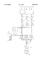
- the gas mixing system for producing high-precision, continuous streams of mixed gases which is shown in this drawing, is provided with a pressure reducing element 1 and a precision pressure regulator 2, such as a needle valve, downstream thereof in each gas line a, b, c for the individual gas components A, B, C.
- a pressure reducing element 1 and a precision pressure regulator 2, such as a needle valve, downstream thereof in each gas line a, b, c for the individual gas components A, B, C.
- Each of gas lines a, b, c leads to a timed valve 5, which valves 5 are connected at the input side via a jointly vented system of lines 3 for pressure equalization.
- the system of lines 3 is vented via a pressure regulator 4, such as a relief valve, as soon as the set pressure level is surpassed.
- the valves 5 are connected via a mixed gas line 8 of small dead volume with a joint outlet aperture 6 opening into a mixing chamber 7.
- the high-precision, continuous mixed gas stream may be withdrawn at the output 9
- all gases supplied must be prepared such that the primary pressure (2 bar, for example) is the same for all gas components A to C at all timed valves 5. This is advantageously achieved by using pressure reducing elements and seemingly "short-circuiting" the gases (lines 3).
- the individual gas components are released by valves 5 at a timed sequence. Switching each valve does not take more than 2 to 4 ms, i.e., a very short time compared to valve opening and closing times. Compensation of mechanical switching delays is essential for high mixing precision.
- the electronic control means 11 for the valves 5 may include a measuring device 12 determining the mechanical switching delays of the individual, timed valves 5, such as a device for measuring the current characteristics of solenoid-actuated, timed valves. Since mechanical switching delays will differ from valve to valve, continual interpretation of current characteristics is recommended in order to compensate switching delays, or, at least, the typical switching delay should be determined once, by means of a suitable measuring method.
- the opening time of the timed valve will be shorter for O 2 than for CO 2 on account of the different flow factors. Furthermore, all other facts referred to above, such as different flow velocities during switchover, compensation of mechanical switching processes, etc. will enter calculation of cycle times.
- the individual gas segments of gas components A to C will combine to form a homogeneous gas mixture.
- the dimensions of the mixing chamber, or rather, its volume should be as large as possible; the maximum size of the mixing chamber will be defined by the duration of the mixing process which is still acceptable.
- the ideal cycle time may be calculated once the size of the mixing chamber is chosen. Good results, with an absolute deviation of ⁇ 0.03% from the target value, were obtained with a dead volume of 12 ⁇ l in the mixed gas line and a cycle time of 2s.
Landscapes
- Physics & Mathematics (AREA)
- General Physics & Mathematics (AREA)
- Engineering & Computer Science (AREA)
- Automation & Control Theory (AREA)
- Accessories For Mixers (AREA)
- Feeding, Discharge, Calcimining, Fusing, And Gas-Generation Devices (AREA)
Applications Claiming Priority (2)
| Application Number | Priority Date | Filing Date | Title |
|---|---|---|---|
| AT0217097A AT406096B (de) | 1997-12-22 | 1997-12-22 | Verfahren und vorrichtung zur erzeugung präziser, kontinuierlicher mischgasströme |
| AT2170/97 | 1997-12-22 |
Publications (1)
| Publication Number | Publication Date |
|---|---|
| US6047719A true US6047719A (en) | 2000-04-11 |
Family
ID=3529229
Family Applications (1)
| Application Number | Title | Priority Date | Filing Date |
|---|---|---|---|
| US09/218,031 Expired - Fee Related US6047719A (en) | 1997-12-22 | 1998-12-22 | Method and device for production of high-precision, continuous streams of mixed gas |
Country Status (3)
| Country | Link |
|---|---|
| US (1) | US6047719A (de) |
| EP (1) | EP0926580A1 (de) |
| AT (1) | AT406096B (de) |
Cited By (7)
| Publication number | Priority date | Publication date | Assignee | Title |
|---|---|---|---|---|
| WO2004020081A3 (en) * | 2002-09-02 | 2004-09-16 | Secretary Trade Ind Brit | Production of variable concentration fluid mixtures |
| US20040240312A1 (en) * | 2002-02-01 | 2004-12-02 | Jean-Louis Gass | Method and device for mixing gases |
| US20080201053A1 (en) * | 2007-02-20 | 2008-08-21 | Esco Technologies (Asia) Pte Ltd | System and method for mixed gas chamber with automatic recovery |
| US20090059717A1 (en) * | 2007-08-31 | 2009-03-05 | Ckd Corporation | Fluid mixing system and fluid mixing apparatus |
| US20100000609A1 (en) * | 2007-02-06 | 2010-01-07 | Brian Arthur Goody | Fluid mixtures |
| WO2010148521A1 (de) * | 2009-06-24 | 2010-12-29 | Miteco Ag | Anlage und verfahren zur kontinuierlichen herstellung eines flüssigkeitsgemisches |
| WO2018096785A1 (ja) * | 2016-11-22 | 2018-05-31 | 株式会社堀場製作所 | 模擬ガス発生装置、評価装置及び模擬ガス発生方法 |
Families Citing this family (2)
| Publication number | Priority date | Publication date | Assignee | Title |
|---|---|---|---|---|
| CN102681559B (zh) * | 2012-05-23 | 2014-03-19 | 首钢京唐钢铁联合有限责任公司 | 一种基于加压机和阀组的燃气混合控制系统及其控制方法 |
| CN105955373B (zh) * | 2016-06-28 | 2018-04-10 | 中冶华天南京电气工程技术有限公司 | 高炉煤气、焦炉煤气和转炉煤气混合控制方法及系统 |
Citations (16)
| Publication number | Priority date | Publication date | Assignee | Title |
|---|---|---|---|---|
| DE2123961A1 (de) * | 1970-05-22 | 1971-12-02 | Avl Ag | Gasmischeinrichtung |
| US3841344A (en) * | 1973-06-06 | 1974-10-15 | Airco Inc | Gas mixing systems |
| US3946104A (en) * | 1973-01-13 | 1976-03-23 | Friedrich Uhde Gmbh | Method of producing an homogeneous gas mixture |
| US4062373A (en) * | 1975-02-07 | 1977-12-13 | Clark Justin S | Method and apparatus for mixing gases |
| US4162689A (en) * | 1977-07-14 | 1979-07-31 | Hoffmann-La Roche Inc. | Time division flow control |
| US4183897A (en) * | 1970-02-23 | 1980-01-15 | Costruzioni Meccaniche G. Mazzoni S.P.A. | Apparatus for admixing liquid and gaseous chemical reactants with uniform pressure in a plurality of reaction tubes |
| EP0056148A1 (de) * | 1980-12-29 | 1982-07-21 | Honeywell B.V. | Beatmungsgerät |
| US4345610A (en) * | 1979-04-20 | 1982-08-24 | Herter Martin | Process and device for the mixing of gases |
| US4345612A (en) * | 1979-06-12 | 1982-08-24 | Citizen Watch Company Limited | Anesthetic gas control apparatus |
| US4377278A (en) * | 1981-05-04 | 1983-03-22 | Mannesmann Aktiengesellschaft | Apparatus for equalizing pressure in shaft furnaces |
| DE3135455A1 (de) * | 1981-09-08 | 1983-04-21 | Drägerwerk AG, 2400 Lübeck | Gasmischvorrichtung |
| US4392514A (en) * | 1981-01-26 | 1983-07-12 | Queue Systems, Inc. | Apparatus and method for precision gas mixing |
| US4526188A (en) * | 1981-05-14 | 1985-07-02 | Siemens Aktiengesellschaft | Process and apparatus for mixing gases in a specific proportion and dosing the resultant gas mixture |
| EP0301824A2 (de) * | 1987-07-30 | 1989-02-01 | The BOC Group plc | Trennung von Gasgemischen |
| US4938256A (en) * | 1987-05-15 | 1990-07-03 | Leybold Aktiengesellschaft | Apparatus for the production of particular concentrations of gaseous materials as well as for mixing various gaseous materials in a specified ratio |
| US5002591A (en) * | 1988-10-14 | 1991-03-26 | Vbm Corporation | High efficiency PSA gas concentrator |
-
1997
- 1997-12-22 AT AT0217097A patent/AT406096B/de not_active IP Right Cessation
-
1998
- 1998-12-03 EP EP98890358A patent/EP0926580A1/de not_active Withdrawn
- 1998-12-22 US US09/218,031 patent/US6047719A/en not_active Expired - Fee Related
Patent Citations (16)
| Publication number | Priority date | Publication date | Assignee | Title |
|---|---|---|---|---|
| US4183897A (en) * | 1970-02-23 | 1980-01-15 | Costruzioni Meccaniche G. Mazzoni S.P.A. | Apparatus for admixing liquid and gaseous chemical reactants with uniform pressure in a plurality of reaction tubes |
| DE2123961A1 (de) * | 1970-05-22 | 1971-12-02 | Avl Ag | Gasmischeinrichtung |
| US3946104A (en) * | 1973-01-13 | 1976-03-23 | Friedrich Uhde Gmbh | Method of producing an homogeneous gas mixture |
| US3841344A (en) * | 1973-06-06 | 1974-10-15 | Airco Inc | Gas mixing systems |
| US4062373A (en) * | 1975-02-07 | 1977-12-13 | Clark Justin S | Method and apparatus for mixing gases |
| US4162689A (en) * | 1977-07-14 | 1979-07-31 | Hoffmann-La Roche Inc. | Time division flow control |
| US4345610A (en) * | 1979-04-20 | 1982-08-24 | Herter Martin | Process and device for the mixing of gases |
| US4345612A (en) * | 1979-06-12 | 1982-08-24 | Citizen Watch Company Limited | Anesthetic gas control apparatus |
| EP0056148A1 (de) * | 1980-12-29 | 1982-07-21 | Honeywell B.V. | Beatmungsgerät |
| US4392514A (en) * | 1981-01-26 | 1983-07-12 | Queue Systems, Inc. | Apparatus and method for precision gas mixing |
| US4377278A (en) * | 1981-05-04 | 1983-03-22 | Mannesmann Aktiengesellschaft | Apparatus for equalizing pressure in shaft furnaces |
| US4526188A (en) * | 1981-05-14 | 1985-07-02 | Siemens Aktiengesellschaft | Process and apparatus for mixing gases in a specific proportion and dosing the resultant gas mixture |
| DE3135455A1 (de) * | 1981-09-08 | 1983-04-21 | Drägerwerk AG, 2400 Lübeck | Gasmischvorrichtung |
| US4938256A (en) * | 1987-05-15 | 1990-07-03 | Leybold Aktiengesellschaft | Apparatus for the production of particular concentrations of gaseous materials as well as for mixing various gaseous materials in a specified ratio |
| EP0301824A2 (de) * | 1987-07-30 | 1989-02-01 | The BOC Group plc | Trennung von Gasgemischen |
| US5002591A (en) * | 1988-10-14 | 1991-03-26 | Vbm Corporation | High efficiency PSA gas concentrator |
Cited By (11)
| Publication number | Priority date | Publication date | Assignee | Title |
|---|---|---|---|---|
| US20040240312A1 (en) * | 2002-02-01 | 2004-12-02 | Jean-Louis Gass | Method and device for mixing gases |
| WO2004020081A3 (en) * | 2002-09-02 | 2004-09-16 | Secretary Trade Ind Brit | Production of variable concentration fluid mixtures |
| US20060144448A1 (en) * | 2002-09-02 | 2006-07-06 | Goody Brian A | Production of variable concentration fluid mixtures |
| US20100000609A1 (en) * | 2007-02-06 | 2010-01-07 | Brian Arthur Goody | Fluid mixtures |
| US20080201053A1 (en) * | 2007-02-20 | 2008-08-21 | Esco Technologies (Asia) Pte Ltd | System and method for mixed gas chamber with automatic recovery |
| US20090059717A1 (en) * | 2007-08-31 | 2009-03-05 | Ckd Corporation | Fluid mixing system and fluid mixing apparatus |
| US8201989B2 (en) * | 2007-08-31 | 2012-06-19 | Ckd Corporation | Fluid mixing system and fluid mixing apparatus |
| WO2010148521A1 (de) * | 2009-06-24 | 2010-12-29 | Miteco Ag | Anlage und verfahren zur kontinuierlichen herstellung eines flüssigkeitsgemisches |
| US8887751B2 (en) | 2009-06-24 | 2014-11-18 | Miteco Ag | System and method for continuously producing a liquid mixture |
| WO2018096785A1 (ja) * | 2016-11-22 | 2018-05-31 | 株式会社堀場製作所 | 模擬ガス発生装置、評価装置及び模擬ガス発生方法 |
| JPWO2018096785A1 (ja) * | 2016-11-22 | 2019-10-17 | 株式会社堀場製作所 | 模擬ガス発生装置、評価装置及び模擬ガス発生方法 |
Also Published As
| Publication number | Publication date |
|---|---|
| ATA217097A (de) | 1999-06-15 |
| AT406096B (de) | 2000-02-25 |
| EP0926580A1 (de) | 1999-06-30 |
Similar Documents
| Publication | Publication Date | Title |
|---|---|---|
| US4219038A (en) | Gas mixing device for breath-protecting, diving, medical and laboratory techniques | |
| US4345610A (en) | Process and device for the mixing of gases | |
| US5049317A (en) | Metering arrangement for a gas mixture | |
| US6047719A (en) | Method and device for production of high-precision, continuous streams of mixed gas | |
| US3762428A (en) | Volumetric gas mixing system | |
| US3878376A (en) | Computer operated solenoid valve pressure control system | |
| JPH10318496A (ja) | ガス容器の充填方法 | |
| US4542740A (en) | Gas dosing device for medical apparatus | |
| US4938256A (en) | Apparatus for the production of particular concentrations of gaseous materials as well as for mixing various gaseous materials in a specified ratio | |
| JP3192286B2 (ja) | 流体計量方法 | |
| US20120000559A1 (en) | Device for mixing at least two gaseous components | |
| US4798531A (en) | Process and apparatus for the control of the air and fuel supply to a plurality of burners | |
| CA2025450A1 (en) | Variable blending dispenser | |
| US3342199A (en) | Digital blend system | |
| US5614655A (en) | Gas mixing device | |
| US10838437B2 (en) | Apparatus for splitting flow of process gas and method of operating same | |
| JP2020525707A (ja) | 燃料消費量測定システム用の圧力制御装置及び燃料消費量測定システム | |
| US5804695A (en) | Gas dividing method and apparatus | |
| US4915123A (en) | Apparatus for preparing gas mixtures from constituents taken in a given proportion | |
| US5880352A (en) | Method and device for determining the concentration of a substance in a gaseous medium | |
| WO1999058835A1 (en) | Engine fuel control system and method | |
| US6178952B1 (en) | Gaseous fuel supply device for an internal combustion engine | |
| JPH11333280A (ja) | 二種ガスによる目的濃度混合ガスの流通式供給方法とその装置 | |
| CN110160609A (zh) | 一种双标准气体流量装置并联式结构及检测方法 | |
| US4651730A (en) | Gas metering device for medical apparatus |
Legal Events
| Date | Code | Title | Description |
|---|---|---|---|
| AS | Assignment |
Owner name: AVL MEDICAL INSTRUMENTS AG, SWITZERLAND Free format text: ASSIGNMENT OF ASSIGNORS INTEREST;ASSIGNORS:RUTHER, HORST;RAITH, ROLAND;REEL/FRAME:009757/0341 Effective date: 19990111 |
|
| REMI | Maintenance fee reminder mailed | ||
| LAPS | Lapse for failure to pay maintenance fees | ||
| FP | Lapsed due to failure to pay maintenance fee |
Effective date: 20040411 |
|
| STCH | Information on status: patent discontinuation |
Free format text: PATENT EXPIRED DUE TO NONPAYMENT OF MAINTENANCE FEES UNDER 37 CFR 1.362 |