US6033031A - Milling machine with vibrating mechanism and rotary drum - Google Patents
Milling machine with vibrating mechanism and rotary drum Download PDFInfo
- Publication number
- US6033031A US6033031A US09/040,203 US4020398A US6033031A US 6033031 A US6033031 A US 6033031A US 4020398 A US4020398 A US 4020398A US 6033031 A US6033031 A US 6033031A
- Authority
- US
- United States
- Prior art keywords
- milling
- machine
- drum
- shaft
- frame
- Prior art date
- Legal status (The legal status is an assumption and is not a legal conclusion. Google has not performed a legal analysis and makes no representation as to the accuracy of the status listed.)
- Expired - Lifetime
Links
Images
Classifications
-
- E—FIXED CONSTRUCTIONS
- E01—CONSTRUCTION OF ROADS, RAILWAYS, OR BRIDGES
- E01C—CONSTRUCTION OF, OR SURFACES FOR, ROADS, SPORTS GROUNDS, OR THE LIKE; MACHINES OR AUXILIARY TOOLS FOR CONSTRUCTION OR REPAIR
- E01C23/00—Auxiliary devices or arrangements for constructing, repairing, reconditioning, or taking-up road or like surfaces
- E01C23/06—Devices or arrangements for working the finished surface; Devices for repairing or reconditioning the surface of damaged paving; Recycling in place or on the road
- E01C23/08—Devices or arrangements for working the finished surface; Devices for repairing or reconditioning the surface of damaged paving; Recycling in place or on the road for roughening or patterning; for removing the surface down to a predetermined depth high spots or material bonded to the surface, e.g. markings; for maintaining earth roads, clay courts or like surfaces by means of surface working tools, e.g. scarifiers, levelling blades
- E01C23/085—Devices or arrangements for working the finished surface; Devices for repairing or reconditioning the surface of damaged paving; Recycling in place or on the road for roughening or patterning; for removing the surface down to a predetermined depth high spots or material bonded to the surface, e.g. markings; for maintaining earth roads, clay courts or like surfaces by means of surface working tools, e.g. scarifiers, levelling blades using power-driven tools, e.g. vibratory tools
Definitions
- the invention relates to milling or cold-planing machines for milling ready-mix concrete or asphalt concrete pavements. More specifically, the invention relates to the milling assembly for such machines.
- the durability and service performance of an asphalt roadway can be affected by a number of variables, including the asphalt mix composition that is used, the construction techniques employed in building the roadway, the overall weight and the axle weight of the vehicles using the roadway, the number and speed of the vehicles and the temperature and other environmental factors under which the roadway is used. Most of these various factors are beyond the control of the road designer. Furthermore, as traffic has increased on the nation's highways and as high-pressure radial tires have become more commonly used on heavy trucks, wear and even deterioration of the roadways has accelerated. Many of the nation's roads have suffered significant rutting damage, and are in need of repair.
- Rutting is a manifestation of differential surface deformation in the wheel paths of a roadway which results from selective densification and shear deformation.
- the amount of pavement rutting depends, at least in part, on the traffic count and loads placed on the roadway and the distribution of such loads across the roadway. It will also be affected by the stresses introduced into the pavement system, and by the permanent strains induced as a result of these stresses. Rutting reduces road serviceability and driving comfort and will reduce the service life of a roadway.
- rutting may also contribute to safety hazards that may arise from an accumulation of water in the rutting paths. Such accumulation may lead to hydroplaning, or in appropriate weather conditions, icing.
- One means of repairing a rutted roadway is to overlay the existing pavement with a new layer (often called a levelling course) of asphalt concrete.
- this method of repair generally results in the application of insufficient quantities of paving material in the rutted areas, because the overlayment will be applied at the same rate per unit of roadway width in the rutted areas (which have a higher surface area across the width) as in the undamaged areas.
- the resulting reduced density in the overlayment of the previously rutted areas will lead to renewed rutting in the new pavement in relatively short order.
- the ruts will be eliminated and the new pavement will have a uniform density across the entire width of the roadway.
- a repaving technique that includes milling a thickness of old pavement and replacing it with an equivalent thickness of new pavement will return the elevation of the roadway to its initial level, whereas the placement of a levelling course atop damaged pavement will tend to raise the surface of the roadway or some portion thereof above its original elevation. This can require the raising of road shoulders, guardrails and manhole covers and the adjustment of overpass clearances, all of which is unnecessary if a proper milling technique is employed.
- a use of milling prior to repaving can also permit ready establishment of the proper road grade and slope, and thereby avoid drainage and safety problems.
- milling typically provides a rough surface that readily accepts and bonds with the new asphalt overlayment.
- milling can provide raw material that can be reclaimed for use in asphalt concrete production. Milling can also be utilized to remove the damaged upper surface of a ready-mix concrete roadway, preparatory to its being repaired or repaved with a layer of asphalt concrete.
- Milling machines are typically wheeled or track-mounted vehicles that are provided with a rotating drum that includes a plurality of cutting teeth.
- the drum is mounted on the frame of the machine and adapted to be lowered into contact with the road surface and rotated about a fixed horizontal axis so as to cut into the surface to a desired depth as the machine is advanced along the roadway.
- Power for rotation of the drum is usually provided by the drive engine for the machine.
- the machine also includes a conveyor system that is designed to carry the milled material that has been cut from the roadway by the rotating drum to a location in front of the machine for deposit into a truck for removal from the site.
- Such machines are designed to cut into the pavement surface to a depth of eight inches (20.32 cm) or more, and for a width of up to 13 feet (3.96 m). Consequently, they are necessarily quite massive and powerful machines. It is not uncommon for a milling machine that is adapted to mill a full-lane width (13 feet) of a roadway to require an engine having up to 1200 hp (895 kW) of power. In addition, the conventional milling process puts considerable physical stress on the cutting teeth and their mounting means on the drum. Cutting tooth wear and breakage is a serious problem in the operation of conventional milling machines. Such machines are therefore somewhat expensive to operate and maintain, and consequently, various methods and devices have been developed to improve efficiencies of operation of the milling machine.
- an improved milling machine could be developed that would increase the efficiency of operation of the machine without substantially increasing its weight, capital cost or operating cost. It would also be desirable if such an improved machine could be developed that would employ the type of cutting teeth that are commonly in use in modern milling machines. It would also be desirable if such a machine could be developed that would permit mounting of such teeth or cutting tools in the manner commonly in use.
- a portable milling machine which machine includes a frame and means for advancing the machine across a surface to be milled.
- the machine also includes a milling assembly mounted on the frame for cutting a width of material from the surface in the path of the machine.
- the milling assembly includes a generally cylindrical milling drum which is mounted for rotation about its axis, which drum is provided with a plurality of cutting teeth.
- a vibratory assembly is also provided, which is mounted so as to impart vibration to the milling drum.
- the vibratory assembly includes an elongate shaft, means for rotating the shaft, and an eccentric weight that is mounted on the shaft, which weight has a non-symmetrical distribution of mass about the shaft so that vibration will be created upon rotation thereof. Also provided is means for isolating the vibratory assembly so as to limit the transmission of vibration created thereby to the frame of the machine.
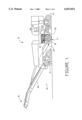
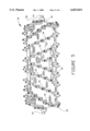
- FIG. 1 is a side elevation view, partly in section, of a milling machine which incorporates a preferred embodiment of the invention.
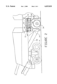
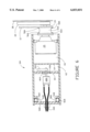
- FIG. 2 is an enlarged view of a portion of the milling machine of FIG. 1, with part of the drive system for the milling drum deleted.
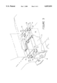
- FIG. 3 is a perspective view of a portion of the preferred embodiment of the invention that is illustrated in FIG. 2.
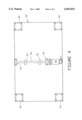
- FIG. 4 is a top view of a portion of the vibratory assembly of the preferred embodiment of the invention that is illustrated in FIGS. 1 through 3, taken along the lines 4--4 of FIG. 2, but excluding the isolator plate.
- FIG. 5 is a front view of the milling drum of the embodiment of the invention that is illustrated in FIGS. 1 through 4.
- FIG. 6 is a sectional view of a milling drum that is identical in external configuration to the drum of FIG. 5 with the cutting teeth and mounting means deleted for simplicity, and that illustrates an alternative embodiment of the invention.
- a milling machine embodying the features of a preferred embodiment of the present invention is indicated generally at 10.
- This machine comprises a portable or mobile vehicle having a frame, a portion of which is shown at 12, and three ground-engaging tracks 14 (two of which are shown in FIG. 1).
- the three or four tracks may all be steerable to provide precise directional control, and they are typically driven by hydraulic motors (not shown), which in turn are powered by engine 16, to advance the machine across the surface of a roadway, parking lot or other surface to be milled.
- the machine includes a milling assembly 17, which includes a generally cylindrical milling drum 18, and which is adapted for cutting a width of material from the surface in the path of the machine.
- the milling assembly is mounted to frame 12 in a conventional way at a medial location along its length.
- the drum of the assembly is mounted for rotation about its axis, a horizontal axis that is generally disposed transverse to the direction of travel "T" of the machine.
- Drum 18 is rotatably driven by engine 16 in a clockwise direction (as indicated by the directional arrow) by means of pulley drive system 20 or by other convenient means, although it may alternatively be driven in a counterclockwise direction.
- System 20 a portion of which is best illustrated in FIG. 6 in connection with an alternative embodiment of the invention, includes an on-off clutch (not shown), drive belt 22, belt coupling 24 and final drive gear box 25, which is mounted, as is conventional, inside the drum.
- Drive arm 26 covers a portion of the drum and some of the components of drive system 20, as shown in FIG. 1.
- Machine 10 is designed to convey the milled roadway material in the forward direction for deposit in a truck (not shown).
- the machine includes a two-part conveyor system.
- This conveyor system includes lower conveyor 28, which has an inlet end 29 located immediately in front of the drum, and upper conveyor 30, which has an elevated outlet end 31 located in front of the frame of the machine.
- This arrangement permits rotation of the drum in the indicated direction to lift the milled material into the inlet end of the conveyor system, which in turn conveys the material to the outlet end (as shown by the directional arrows), where it may be deposited into a truck.
- milling drum 18 includes a cylindrical outer surface 32 which is arranged coaxially with end mounting shafts 34.
- a plurality of tooth-mounting assemblies 36 are fixed to the surface of the drum, as by welding, and in this particular embodiment of the invention, the assemblies are arranged to define oppositely directed helices.
- the drum includes a plurality of cutter teeth 38 that are attached to the mounting assemblies in a conventional manner.
- conventional milling drums are equipped with 100-200 cutting teeth having tungsten carbide tips, and are designed to be rotated at average speeds of 75-120 rpm to optimize productivity and minimize tooth wear.
- gear box 25 is employed. This gear box is preferably a planetary gear box, which operates at a total efficiency of about 90%.
- a milling machine provides 300 hp (224 kW), for example, to drive the milling drum, approximately 30 hp (22 kW) will be lost in the gear box, primarily as heat. Consequently, the gear box is generally immersed in a coolant, which permits transfer of heat from the outer surface of the gear box to the wall of the milling drum, for transfer therethrough to the atmosphere.
- milling machine 10 includes cutter enclosure 40, in which drum 18 is mounted. As shown in FIG. 3, enclosure 40 is provided with opening 41 to accommodate inlet end 29 of lower conveyor 28.
- the milling machine also includes vibratory assembly 42, which is mounted so as to impart vibration to the milling drum.
- assembly 42 is mounted atop vibrator plate 44 by any convenient means, and plate 44 is rigidly mounted on top of enclosure 40, preferably by welding.
- the vibratory assembly includes an elongate shaft 46, and means for rotating the shaft, such as hydraulic motor 48.
- the shaft is supported by and journaled in at least one bearing assembly, such as assembly 49.
- Assembly 42 also includes an eccentric weight, such as weight 50, that is mounted on the shaft.
- weights 50 are mounted so as to have a non-symmetrical distribution of mass about shaft 46 so that vibration will be created upon rotation thereof.
- the milling assembly also includes means for isolating the vibratory assembly so as to limit the transmission of vibration created thereby to the frame of the machine.
- isolator plate 52 is rigidly mounted to frame 12 by any convenient means, and at least one elastomeric pad, such as pad 54, is positioned between the vibratory assembly and the isolator plate so as to limit the transmission of vibration created by the vibratory assembly to the frame.
- pad 54 is positioned between the vibratory assembly 42 and isolator plate 52 of the machine, although any convenient number of pads may be used.
- these pads are made of natural or synthetic rubber or other suitable elastomeric material, and are attached to vibrator plate 44 by means of bolts 56, and to isolator plate 52 by means of bolts 58.
- FIG. 6 shows a sectional view of milling drum 18A, which is identical in external configuration to drum 18, although such is not shown in the drawings.
- the vibratory assembly of this alternative embodiment of the invention is located within drum 18A.
- hydraulic motor 48A is mounted to bulkhead 60 by any convenient means (not shown).
- Motor 48A turns shaft 46A, which is supported by and journaled in bearing 49A.
- shaft 46A is aligned with the axis of the milling drum.
- Weight 50A is mounted, in an eccentric fashion, to shaft 46A so that the weight may rotate in an airspace 62 enclosed by bulkheads 60 and 64.
- This latter bulkhead isolates the vibration assembly from fluid chamber 66, in which is provided the coolant for gear box 25. Vibration from the vibratory assembly is isolated from the frame 12 of the milling machine by elastomeric isolator pads 54A and 54B. Pads 54A and 54B may be made of natural or synthetic rubber or other suitable elastomeric material, and are attached to the drum, preferably using bolts 56A and 56B respectively, and to the frame of the machine, preferably using bolts 58A and 58B respectively.
- the vibratory assembly of the invention operates to apply a series of forces to the milling drum that will enhance its cutting or milling performance.
- the arrangement of the components of the vibratory assembly and the isolation means in the preferred embodiments of the invention will serve to direct these vibratory forces towards the pavement surface and substantially perpendicular to the direction of travel. It has been found that when such vibratory forces are isolated to the milling assembly and so directed, the mass of the vibratory assembly and the forces created thereby may be utilized for application of greater cutting forces through the milling drum than had previously been thought possible.
Landscapes
- Engineering & Computer Science (AREA)
- Mechanical Engineering (AREA)
- Mining & Mineral Resources (AREA)
- Architecture (AREA)
- Civil Engineering (AREA)
- Structural Engineering (AREA)
- Road Repair (AREA)
Abstract
Description
Claims (15)
Priority Applications (1)
| Application Number | Priority Date | Filing Date | Title |
|---|---|---|---|
| US09/040,203 US6033031A (en) | 1998-03-13 | 1998-03-13 | Milling machine with vibrating mechanism and rotary drum |
Applications Claiming Priority (1)
| Application Number | Priority Date | Filing Date | Title |
|---|---|---|---|
| US09/040,203 US6033031A (en) | 1998-03-13 | 1998-03-13 | Milling machine with vibrating mechanism and rotary drum |
Publications (1)
| Publication Number | Publication Date |
|---|---|
| US6033031A true US6033031A (en) | 2000-03-07 |
Family
ID=21909704
Family Applications (1)
| Application Number | Title | Priority Date | Filing Date |
|---|---|---|---|
| US09/040,203 Expired - Lifetime US6033031A (en) | 1998-03-13 | 1998-03-13 | Milling machine with vibrating mechanism and rotary drum |
Country Status (1)
| Country | Link |
|---|---|
| US (1) | US6033031A (en) |
Cited By (17)
| Publication number | Priority date | Publication date | Assignee | Title |
|---|---|---|---|---|
| US20030127905A1 (en) * | 2002-01-09 | 2003-07-10 | Haroldsen J. Tron | Systems and methods for milling paving material with increased stability, support, and power |
| US20040035007A1 (en) * | 2000-03-13 | 2004-02-26 | Burgess John Elliott | Attachment for a percussive tool |
| US20060214041A1 (en) * | 2005-03-23 | 2006-09-28 | Yao Jing J | Vibratory milling machine having linear reciprocating motion |
| US20080253834A1 (en) * | 2007-04-05 | 2008-10-16 | Power Curbers, Inc. | 3d control system for construction machines |
| US20090020388A1 (en) * | 2007-07-20 | 2009-01-22 | Wirtgen Gmbh | Construction machine, as well as clutch for switching the power flow |
| US20090127918A1 (en) * | 2005-03-23 | 2009-05-21 | Longyear Tm, Inc. | Vibratory milling machine having linear reciprocating motion |
| CN101881034A (en) * | 2010-07-23 | 2010-11-10 | 北京华洋建设开发有限公司 | Milling and planing system |
| US8083434B1 (en) | 2009-07-13 | 2011-12-27 | Gorman Bros., Inc. | Pavement rehabilitation using cold in-place asphalt pavement recycling |
| US20130082507A1 (en) * | 2010-04-16 | 2013-04-04 | Bomag Gmbh | Method for operating a ground milling machine with height-adjustable milling roller |
| US20140308075A1 (en) * | 2011-12-22 | 2014-10-16 | Caterpillar Paving Products Inc. | Automatic Four Leg Leveling for Cold Planers |
| US20150227120A1 (en) * | 2014-02-12 | 2015-08-13 | Bomag Gmbh | Method For Optimizing An Operating Function Of A Ground Milling Machine And Ground Milling Machine |
| WO2016191900A1 (en) * | 2015-06-04 | 2016-12-08 | 唐忠盛 | Vibrating surface mining machine |
| WO2018098599A1 (en) | 2016-11-29 | 2018-06-07 | Ammann Schweiz Ag | Method and device for milling stone material or stone-like material |
| US10024005B2 (en) * | 2014-12-30 | 2018-07-17 | Wirtgen Gmbh | Self-propelled road milling machine for working road surfaces, as well as method for working road surfaces with a road milling machine |
| CN109610277A (en) * | 2018-10-26 | 2019-04-12 | 赵智慧 | A kind of construction site ground cement laying apparatus |
| US10323364B2 (en) | 2017-09-15 | 2019-06-18 | Coneqtec Corp. | Asphalt milling cutter arrangements |
| US20210010269A1 (en) * | 2019-07-11 | 2021-01-14 | Columbia Construction Services, Inc. | Roof removal device |
Citations (17)
| Publication number | Priority date | Publication date | Assignee | Title |
|---|---|---|---|---|
| US3072391A (en) * | 1960-06-21 | 1963-01-08 | James F Mcdarrah | Disintegrating machine having cutting and impact action |
| US3504598A (en) * | 1969-01-22 | 1970-04-07 | Rex Chainbelt Inc | Pulverizer-mixer with a vibratory tailboard |
| US3703128A (en) * | 1969-10-08 | 1972-11-21 | Vibro Verken Ab | Vibrating roller |
| US3706474A (en) * | 1970-06-11 | 1972-12-19 | Henry Neuenburg | Motor-driven chiseling device |
| US4172679A (en) * | 1975-09-23 | 1979-10-30 | Reinhard Wirtgen | Device for renewing road surfaces |
| US4434944A (en) * | 1981-10-28 | 1984-03-06 | Bodine Albert G | Mass (inductive) reactance vibratory mill or crusher employing mechanical drive force |
| US4463509A (en) * | 1983-03-11 | 1984-08-07 | J.I. Case Company | Vibratory plow assembly |
| US4586849A (en) * | 1983-12-01 | 1986-05-06 | Nuclear Protection Systems, Inc. | Nuclear disposal method and system |
| US4619552A (en) * | 1984-08-02 | 1986-10-28 | Sakai Heavy Industries Ltd. | Vibration proof suspension type vibrating roller |
| US4732507A (en) * | 1987-03-03 | 1988-03-22 | M-B-W, Inc. | Walk behind soil compactor having a double vibratory drum and an articulated frame |
| US4775262A (en) * | 1987-07-21 | 1988-10-04 | Cmi Corporation | Concrete finishing machine with vibrating compactor unit |
| US4993869A (en) * | 1989-04-07 | 1991-02-19 | Cmi Corporation | Concrete finishing machine with vibrating finishing rollers |
| US5046891A (en) * | 1989-03-01 | 1991-09-10 | Bomag Gmbh | Vibrator roller for soil compaction |
| US5062228A (en) * | 1990-07-02 | 1991-11-05 | M-B-W Inc. | Compactor and blade attachment for loader |
| US5078540A (en) * | 1990-08-24 | 1992-01-07 | Astec Industries, Inc. | Asphalt pavement milling machine and cutter drum therefor |
| US5244306A (en) * | 1992-03-31 | 1993-09-14 | M-B-W Inc. | Vibratory compactor attachment for mechanical equipment |
| US5505598A (en) * | 1994-07-29 | 1996-04-09 | Wirtgen America, Inc. | Milling machine with multi-width cutter |
-
1998
- 1998-03-13 US US09/040,203 patent/US6033031A/en not_active Expired - Lifetime
Patent Citations (17)
| Publication number | Priority date | Publication date | Assignee | Title |
|---|---|---|---|---|
| US3072391A (en) * | 1960-06-21 | 1963-01-08 | James F Mcdarrah | Disintegrating machine having cutting and impact action |
| US3504598A (en) * | 1969-01-22 | 1970-04-07 | Rex Chainbelt Inc | Pulverizer-mixer with a vibratory tailboard |
| US3703128A (en) * | 1969-10-08 | 1972-11-21 | Vibro Verken Ab | Vibrating roller |
| US3706474A (en) * | 1970-06-11 | 1972-12-19 | Henry Neuenburg | Motor-driven chiseling device |
| US4172679A (en) * | 1975-09-23 | 1979-10-30 | Reinhard Wirtgen | Device for renewing road surfaces |
| US4434944A (en) * | 1981-10-28 | 1984-03-06 | Bodine Albert G | Mass (inductive) reactance vibratory mill or crusher employing mechanical drive force |
| US4463509A (en) * | 1983-03-11 | 1984-08-07 | J.I. Case Company | Vibratory plow assembly |
| US4586849A (en) * | 1983-12-01 | 1986-05-06 | Nuclear Protection Systems, Inc. | Nuclear disposal method and system |
| US4619552A (en) * | 1984-08-02 | 1986-10-28 | Sakai Heavy Industries Ltd. | Vibration proof suspension type vibrating roller |
| US4732507A (en) * | 1987-03-03 | 1988-03-22 | M-B-W, Inc. | Walk behind soil compactor having a double vibratory drum and an articulated frame |
| US4775262A (en) * | 1987-07-21 | 1988-10-04 | Cmi Corporation | Concrete finishing machine with vibrating compactor unit |
| US5046891A (en) * | 1989-03-01 | 1991-09-10 | Bomag Gmbh | Vibrator roller for soil compaction |
| US4993869A (en) * | 1989-04-07 | 1991-02-19 | Cmi Corporation | Concrete finishing machine with vibrating finishing rollers |
| US5062228A (en) * | 1990-07-02 | 1991-11-05 | M-B-W Inc. | Compactor and blade attachment for loader |
| US5078540A (en) * | 1990-08-24 | 1992-01-07 | Astec Industries, Inc. | Asphalt pavement milling machine and cutter drum therefor |
| US5244306A (en) * | 1992-03-31 | 1993-09-14 | M-B-W Inc. | Vibratory compactor attachment for mechanical equipment |
| US5505598A (en) * | 1994-07-29 | 1996-04-09 | Wirtgen America, Inc. | Milling machine with multi-width cutter |
Cited By (35)
| Publication number | Priority date | Publication date | Assignee | Title |
|---|---|---|---|---|
| US20040035007A1 (en) * | 2000-03-13 | 2004-02-26 | Burgess John Elliott | Attachment for a percussive tool |
| US20030127905A1 (en) * | 2002-01-09 | 2003-07-10 | Haroldsen J. Tron | Systems and methods for milling paving material with increased stability, support, and power |
| US20070116519A1 (en) * | 2002-01-09 | 2007-05-24 | Haroldsen J T | Systems and Methods for Milling Paving Material with Increased Stability, Support, and Power |
| US7144087B2 (en) * | 2002-01-09 | 2006-12-05 | Asph{dot over (a)}lt Zipper, Inc. | Systems and methods for milling paving material with increased stability, support, and power |
| US20090072061A1 (en) * | 2005-03-23 | 2009-03-19 | Longyear Tm, Inc. | Continuous vibratory milling machine |
| US7434890B2 (en) * | 2005-03-23 | 2008-10-14 | Boart Longyear Inc. | Vibratory milling machine having linear reciprocating motion |
| US20060214041A1 (en) * | 2005-03-23 | 2006-09-28 | Yao Jing J | Vibratory milling machine having linear reciprocating motion |
| US8056985B2 (en) | 2005-03-23 | 2011-11-15 | Longyear Tm, Inc. | Vibratory machine |
| US20090127918A1 (en) * | 2005-03-23 | 2009-05-21 | Longyear Tm, Inc. | Vibratory milling machine having linear reciprocating motion |
| US7828393B2 (en) | 2005-03-23 | 2010-11-09 | Boart Longyear Inc. | Continuous vibratory milling machine |
| US8079647B2 (en) | 2005-03-23 | 2011-12-20 | Longyear Tm, Inc. | Vibratory milling machine having linear reciprocating motion |
| US20110036630A1 (en) * | 2005-03-23 | 2011-02-17 | Boart Longyear Inc. | Vibratory drilling machine |
| US20080253834A1 (en) * | 2007-04-05 | 2008-10-16 | Power Curbers, Inc. | 3d control system for construction machines |
| US20080253835A1 (en) * | 2007-04-05 | 2008-10-16 | Power Curbers, Inc. | Automated stringline installation system |
| US8073566B2 (en) | 2007-04-05 | 2011-12-06 | Power Curbers, Inc. | Automated stringline installation system |
| US8068962B2 (en) | 2007-04-05 | 2011-11-29 | Power Curbers, Inc. | 3D control system for construction machines |
| US20090020388A1 (en) * | 2007-07-20 | 2009-01-22 | Wirtgen Gmbh | Construction machine, as well as clutch for switching the power flow |
| US7992696B2 (en) * | 2007-07-20 | 2011-08-09 | Wirtgen Gmbh | Construction machine, as well as clutch for switching the power flow |
| US8261898B2 (en) | 2007-07-20 | 2012-09-11 | Wirtgen Gmbh | Construction machine, as well as clutch for switching the power flow |
| US8202021B2 (en) | 2009-07-13 | 2012-06-19 | Gorman Bros., Inc. | Pavement rehabilitation using cold in-place asphalt pavement recycling |
| US8083434B1 (en) | 2009-07-13 | 2011-12-27 | Gorman Bros., Inc. | Pavement rehabilitation using cold in-place asphalt pavement recycling |
| US8960806B2 (en) * | 2010-04-16 | 2015-02-24 | Bomag Gmbh | Method for operating a ground milling machine with height-adjustable milling roller |
| US20130082507A1 (en) * | 2010-04-16 | 2013-04-04 | Bomag Gmbh | Method for operating a ground milling machine with height-adjustable milling roller |
| CN101881034B (en) * | 2010-07-23 | 2011-08-31 | 北京华洋建设开发有限公司 | Milling and planing system |
| CN101881034A (en) * | 2010-07-23 | 2010-11-10 | 北京华洋建设开发有限公司 | Milling and planing system |
| US20140308075A1 (en) * | 2011-12-22 | 2014-10-16 | Caterpillar Paving Products Inc. | Automatic Four Leg Leveling for Cold Planers |
| US9206566B2 (en) * | 2011-12-22 | 2015-12-08 | Caterpillar Paving Products Inc. | Automatic four leg leveling for cold planers |
| US9864347B2 (en) * | 2014-02-12 | 2018-01-09 | Bomag Gmbh | Method for optimizing an operating function of a ground milling machine and ground milling machine |
| US20150227120A1 (en) * | 2014-02-12 | 2015-08-13 | Bomag Gmbh | Method For Optimizing An Operating Function Of A Ground Milling Machine And Ground Milling Machine |
| US10024005B2 (en) * | 2014-12-30 | 2018-07-17 | Wirtgen Gmbh | Self-propelled road milling machine for working road surfaces, as well as method for working road surfaces with a road milling machine |
| WO2016191900A1 (en) * | 2015-06-04 | 2016-12-08 | 唐忠盛 | Vibrating surface mining machine |
| WO2018098599A1 (en) | 2016-11-29 | 2018-06-07 | Ammann Schweiz Ag | Method and device for milling stone material or stone-like material |
| US10323364B2 (en) | 2017-09-15 | 2019-06-18 | Coneqtec Corp. | Asphalt milling cutter arrangements |
| CN109610277A (en) * | 2018-10-26 | 2019-04-12 | 赵智慧 | A kind of construction site ground cement laying apparatus |
| US20210010269A1 (en) * | 2019-07-11 | 2021-01-14 | Columbia Construction Services, Inc. | Roof removal device |
Similar Documents
| Publication | Publication Date | Title |
|---|---|---|
| US6033031A (en) | Milling machine with vibrating mechanism and rotary drum | |
| US7396085B2 (en) | Pavement degradation tools in a ganged configuration | |
| US7387464B2 (en) | Pavement trimming tool | |
| US5722789A (en) | Multi-width cutter | |
| US4193636A (en) | Asphalt paving planer with conveyor forwardly of cutting drum | |
| CN104508206A (en) | Milling drum having integral tool mounting blocks | |
| US20120068524A1 (en) | Multiple Milling Drums Secured to the Underside of a Single Milling Machine | |
| US4560207A (en) | Method and apparatus for fragmenting asphalt | |
| US20150330037A1 (en) | Method of grinding a two-lane roadway in two passes | |
| US5664907A (en) | Apparatus and method for removing and pulverizing steel reinforced pavement | |
| EP0096585A1 (en) | An earth working machine | |
| US3606469A (en) | Apparatus for cutting concrete and similar roadway surfaces | |
| WO2007145576A2 (en) | Method for providing an improved road surface, use of a grinding assembly for renovating a roadway, and a tool and method fur such renovation | |
| US11613855B1 (en) | System and method of material evacuation in mill chamber | |
| US10865528B2 (en) | Side cutter for milling machine | |
| EP0735193B1 (en) | A perfected road scarifying machine for the removal of road surfacings | |
| US2314934A (en) | Highway maintaining device | |
| CN111910497B (en) | Town road damages bituminous paving cutting clean-up equipment | |
| CN110241772B (en) | Large-scale snow removing ice operating mechanism with firmer combination of shovel blades | |
| KR100618622B1 (en) | Rumble strip milling machine | |
| EP0735192B1 (en) | A road scarifying machine with a perfected milling drum for the removal of road surfacings | |
| EP3717702B1 (en) | Device and method for processing a surface | |
| CN112647394A (en) | Torque limiting device for a road milling machine | |
| CN111593637A (en) | Road pavement broken stone flattening equipment | |
| US11591162B2 (en) | Conveyor system for material transport on cold planer |
Legal Events
| Date | Code | Title | Description |
|---|---|---|---|
| AS | Assignment |
Owner name: ASTEC INDUSTRIES, INC., TENNESSEE Free format text: ASSIGNMENT OF ASSIGNORS INTEREST;ASSIGNOR:CAMPBELL, THOMAS R.;REEL/FRAME:009049/0301 Effective date: 19980302 |
|
| STCF | Information on status: patent grant |
Free format text: PATENTED CASE |
|
| AS | Assignment |
Owner name: ROADTEC, INC., TENNESSEE Free format text: ASSIGNMENT OF ASSIGNORS INTEREST;ASSIGNOR:ASTEC INDUSTRIES, INC.;REEL/FRAME:012729/0070 Effective date: 20010601 Owner name: RI PROPERTIES, INC., MINNESOTA Free format text: ASSIGNMENT OF ASSIGNORS INTEREST;ASSIGNOR:ROADTEC, INC.;REEL/FRAME:012729/0103 Effective date: 20010601 |
|
| AS | Assignment |
Owner name: BANK ONE, NA, AS AGENT, ILLINOIS Free format text: SECURITY AGREEMENT;ASSIGNOR:RI PROPERTIES, INC.;REEL/FRAME:014027/0260 Effective date: 20030411 |
|
| FPAY | Fee payment |
Year of fee payment: 4 |
|
| AS | Assignment |
Owner name: GENERAL ELECTRIC CAPITAL CORPORATION, TEXAS Free format text: SECURITY AGREEMENT;ASSIGNORS:ASTEC INDUSTRIES, INC.;ASTEC, INC.;HEATEC, INC.;AND OTHERS;REEL/FRAME:014186/0319 Effective date: 20030514 |
|
| AS | Assignment |
Owner name: GENERAL ELECTRIC CAPITAL CANADA, INC., GEORGIA Free format text: SECURITY INTEREST;ASSIGNORS:ASTEC INDUSTRIES, INC;ASTEC, INC;HEATEC, INC.;AND OTHERS;REEL/FRAME:015201/0777 Effective date: 20030514 |
|
| AS | Assignment |
Owner name: AI DEVELOPMENT GROUP, INC., A MINNESOTA CORPORATIO Free format text: RELEASE BY SECURED PARTY;ASSIGNOR:GENERAL ELECTRIC CAPITAL CORPORATION;REEL/FRAME:017105/0823 Effective date: 20051031 Owner name: AI ENTERPRISES, INC., A MINNESOTA CORPORATION, TEN Free format text: RELEASE BY SECURED PARTY;ASSIGNOR:GENERAL ELECTRIC CAPITAL CORPORATION;REEL/FRAME:017105/0823 Effective date: 20051031 Owner name: ASTEC TRANSPORTATION, INC., A TENNESSEE CORPORATIO Free format text: RELEASE BY SECURED PARTY;ASSIGNOR:GENERAL ELECTRIC CAPITAL CORPORATION;REEL/FRAME:017105/0823 Effective date: 20051031 Owner name: AMERICAN AUGERS, INC., A DELAWARE CORPORATION, TEN Free format text: RELEASE BY SECURED PARTY;ASSIGNOR:GENERAL ELECTRIC CAPITAL CORPORATION;REEL/FRAME:017105/0823 Effective date: 20051031 Owner name: ASTEC HOLDINGS, INC., A TENNESSEE CORPORATION, TEN Free format text: RELEASE BY SECURED PARTY;ASSIGNOR:GENERAL ELECTRIC CAPITAL CORPORATION;REEL/FRAME:017105/0823 Effective date: 20051031 Owner name: SUPERIOR INDUSTRIES OF MORRIS, INC., A MINNESOTA C Free format text: RELEASE BY SECURED PARTY;ASSIGNOR:GENERAL ELECTRIC CAPITAL CORPORATION;REEL/FRAME:017105/0823 Effective date: 20051031 Owner name: RI PROPERTIES, INC., A MINNESOTA CORPORATION, TENN Free format text: RELEASE BY SECURED PARTY;ASSIGNOR:GENERAL ELECTRIC CAPITAL CORPORATION;REEL/FRAME:017105/0823 Effective date: 20051031 Owner name: ASTEC INVESTMENTS, INC., A TENNESSEE CORPORATION, Free format text: RELEASE BY SECURED PARTY;ASSIGNOR:GENERAL ELECTRIC CAPITAL CORPORATION;REEL/FRAME:017105/0823 Effective date: 20051031 Owner name: TI SERVICES, INC., A MINNESOTA CORPORATION, TENNES Free format text: RELEASE BY SECURED PARTY;ASSIGNOR:GENERAL ELECTRIC CAPITAL CORPORATION;REEL/FRAME:017105/0823 Effective date: 20051031 Owner name: JOHNSON CRUSHERS INTERNATIONAL, INC., A TENNESSEE Free format text: RELEASE BY SECURED PARTY;ASSIGNOR:GENERAL ELECTRIC CAPITAL CORPORATION;REEL/FRAME:017105/0823 Effective date: 20051031 Owner name: HEATEC, INC., A TENNESSEE CORPORATION, TENNESSEE Free format text: RELEASE BY SECURED PARTY;ASSIGNOR:GENERAL ELECTRIC CAPITAL CORPORATION;REEL/FRAME:017105/0823 Effective date: 20051031 Owner name: ASTEC INDUSTRIES, INC., A TENNESSEE CORPORATION, T Free format text: RELEASE BY SECURED PARTY;ASSIGNOR:GENERAL ELECTRIC CAPITAL CORPORATION;REEL/FRAME:017105/0823 Effective date: 20051031 Owner name: TELSMITH, INC., A DELAWARE CORPORATION, TENNESSEE Free format text: RELEASE BY SECURED PARTY;ASSIGNOR:GENERAL ELECTRIC CAPITAL CORPORATION;REEL/FRAME:017105/0823 Effective date: 20051031 Owner name: CEI ENTERPRISES, INC., A TENNESSEE CORPORATION, TE Free format text: RELEASE BY SECURED PARTY;ASSIGNOR:GENERAL ELECTRIC CAPITAL CORPORATION;REEL/FRAME:017105/0823 Effective date: 20051031 Owner name: ASTEC SYSTEMS, INC., A TENNESSEE CORPORATION, TENN Free format text: RELEASE BY SECURED PARTY;ASSIGNOR:GENERAL ELECTRIC CAPITAL CORPORATION;REEL/FRAME:017105/0823 Effective date: 20051031 Owner name: ASTEC, INC., A TENNESSEE CORPORATION, TENNESSEE Free format text: RELEASE BY SECURED PARTY;ASSIGNOR:GENERAL ELECTRIC CAPITAL CORPORATION;REEL/FRAME:017105/0823 Effective date: 20051031 Owner name: PRODUCTION ENGINEERED PRODUCTS, INC., A NEVADA COR Free format text: RELEASE BY SECURED PARTY;ASSIGNOR:GENERAL ELECTRIC CAPITAL CORPORATION;REEL/FRAME:017105/0823 Effective date: 20051031 Owner name: CARLSON PAVING PRODUCTS, INC., A WASHINGTON CORPOR Free format text: RELEASE BY SECURED PARTY;ASSIGNOR:GENERAL ELECTRIC CAPITAL CORPORATION;REEL/FRAME:017105/0823 Effective date: 20051031 Owner name: BREAKER TECHNOLOGY, INC., A TENNESSEE CORPORATION, Free format text: RELEASE BY SECURED PARTY;ASSIGNOR:GENERAL ELECTRIC CAPITAL CORPORATION;REEL/FRAME:017105/0823 Effective date: 20051031 Owner name: KOLBERG-PIONEER, INC., A TENNESSEE CORPORATION, TE Free format text: RELEASE BY SECURED PARTY;ASSIGNOR:GENERAL ELECTRIC CAPITAL CORPORATION;REEL/FRAME:017105/0823 Effective date: 20051031 Owner name: ROADTEC, INC., A TENNESSEE CORPORATION, TENNESSEE Free format text: RELEASE BY SECURED PARTY;ASSIGNOR:GENERAL ELECTRIC CAPITAL CORPORATION;REEL/FRAME:017105/0823 Effective date: 20051031 Owner name: TRENCOR, INC., A TEXAS CORPORATION, TENNESSEE Free format text: RELEASE BY SECURED PARTY;ASSIGNOR:GENERAL ELECTRIC CAPITAL CORPORATION;REEL/FRAME:017105/0823 Effective date: 20051031 |
|
| AS | Assignment |
Owner name: KOLBERG-PIONEER, INC., A TENNESSEE CORPORATION, TE Free format text: RELEASE BY SECURED PARTY;ASSIGNOR:GENERAL ELECTRIC CAPITAL CANADA, INC., A CANADA CORPORATION;REEL/FRAME:017115/0340 Effective date: 20051031 Owner name: ASTEC HOLDINGS, INC., A TENNESSEE CORPORATION, TEN Free format text: RELEASE BY SECURED PARTY;ASSIGNOR:GENERAL ELECTRIC CAPITAL CANADA, INC., A CANADA CORPORATION;REEL/FRAME:017115/0340 Effective date: 20051031 Owner name: PRODUCTION ENGINEERED PRODUCTS, INC., A NEVADA COR Free format text: RELEASE BY SECURED PARTY;ASSIGNOR:GENERAL ELECTRIC CAPITAL CANADA, INC., A CANADA CORPORATION;REEL/FRAME:017115/0340 Effective date: 20051031 Owner name: AMERICAN AUGERS, INC., A DELAWARE CORPORATION, TEN Free format text: RELEASE BY SECURED PARTY;ASSIGNOR:GENERAL ELECTRIC CAPITAL CANADA, INC., A CANADA CORPORATION;REEL/FRAME:017115/0340 Effective date: 20051031 Owner name: BREAKER TECHNOLOGY, INC., A TENNESSEE CORPORATION, Free format text: RELEASE BY SECURED PARTY;ASSIGNOR:GENERAL ELECTRIC CAPITAL CANADA, INC., A CANADA CORPORATION;REEL/FRAME:017115/0340 Effective date: 20051031 Owner name: CARLSON PAVING PRODUCTS, INC., A WASHINGTON CORPOR Free format text: RELEASE BY SECURED PARTY;ASSIGNOR:GENERAL ELECTRIC CAPITAL CANADA, INC., A CANADA CORPORATION;REEL/FRAME:017115/0340 Effective date: 20051031 Owner name: ASTEC SYSTEMS, INC., A TENNESSEE CORPORATION, TENN Free format text: RELEASE BY SECURED PARTY;ASSIGNOR:GENERAL ELECTRIC CAPITAL CANADA, INC., A CANADA CORPORATION;REEL/FRAME:017115/0340 Effective date: 20051031 Owner name: TRENCOR, INC., A TEXAS CORPORATION, TENNESSEE Free format text: RELEASE BY SECURED PARTY;ASSIGNOR:GENERAL ELECTRIC CAPITAL CANADA, INC., A CANADA CORPORATION;REEL/FRAME:017115/0340 Effective date: 20051031 Owner name: ASTEC, INC., A TENNESSEE CORPORATION, TENNESSEE Free format text: RELEASE BY SECURED PARTY;ASSIGNOR:GENERAL ELECTRIC CAPITAL CANADA, INC., A CANADA CORPORATION;REEL/FRAME:017115/0340 Effective date: 20051031 Owner name: JOHNSON CRUSHERS INTERNATIONAL, INC., A TENNESSEE Free format text: RELEASE BY SECURED PARTY;ASSIGNOR:GENERAL ELECTRIC CAPITAL CANADA, INC., A CANADA CORPORATION;REEL/FRAME:017115/0340 Effective date: 20051031 Owner name: HEATEC, INC., A TENNESSEE CORPORATION, TENNESSEE Free format text: RELEASE BY SECURED PARTY;ASSIGNOR:GENERAL ELECTRIC CAPITAL CANADA, INC., A CANADA CORPORATION;REEL/FRAME:017115/0340 Effective date: 20051031 Owner name: AI ENTERPRISES, INC., A MINNESOTA CORPORATION, TEN Free format text: RELEASE BY SECURED PARTY;ASSIGNOR:GENERAL ELECTRIC CAPITAL CANADA, INC., A CANADA CORPORATION;REEL/FRAME:017115/0340 Effective date: 20051031 Owner name: ASTEC TRANSPORTATION, INC., A TENNESSEE CORPORATIO Free format text: RELEASE BY SECURED PARTY;ASSIGNOR:GENERAL ELECTRIC CAPITAL CANADA, INC., A CANADA CORPORATION;REEL/FRAME:017115/0340 Effective date: 20051031 Owner name: AI DEVELOPMENT GROUP, INC., A MINNESOTA CORPORATIO Free format text: RELEASE BY SECURED PARTY;ASSIGNOR:GENERAL ELECTRIC CAPITAL CANADA, INC., A CANADA CORPORATION;REEL/FRAME:017115/0340 Effective date: 20051031 Owner name: SUPERIOR INDUSTRIES OF MORRIS, INC., A MINNESOTA C Free format text: RELEASE BY SECURED PARTY;ASSIGNOR:GENERAL ELECTRIC CAPITAL CANADA, INC., A CANADA CORPORATION;REEL/FRAME:017115/0340 Effective date: 20051031 Owner name: CEI ENTERPRISES, INC., A TENNESSEE CORPORATION, TE Free format text: RELEASE BY SECURED PARTY;ASSIGNOR:GENERAL ELECTRIC CAPITAL CANADA, INC., A CANADA CORPORATION;REEL/FRAME:017115/0340 Effective date: 20051031 Owner name: TI SERVICES, INC., A MINNESOTA CORPORATION, TENNES Free format text: RELEASE BY SECURED PARTY;ASSIGNOR:GENERAL ELECTRIC CAPITAL CANADA, INC., A CANADA CORPORATION;REEL/FRAME:017115/0340 Effective date: 20051031 Owner name: TELSMITH, INC., A DELAWARE CORPORATION, TENNESSEE Free format text: RELEASE BY SECURED PARTY;ASSIGNOR:GENERAL ELECTRIC CAPITAL CANADA, INC., A CANADA CORPORATION;REEL/FRAME:017115/0340 Effective date: 20051031 Owner name: ASTEC INVESTMENTS, INC., A TENNESSEE CORPORATION, Free format text: RELEASE BY SECURED PARTY;ASSIGNOR:GENERAL ELECTRIC CAPITAL CANADA, INC., A CANADA CORPORATION;REEL/FRAME:017115/0340 Effective date: 20051031 Owner name: ASTEC INDUSTRIES, INC., A TENNESSEE CORPORATION, T Free format text: RELEASE BY SECURED PARTY;ASSIGNOR:GENERAL ELECTRIC CAPITAL CANADA, INC., A CANADA CORPORATION;REEL/FRAME:017115/0340 Effective date: 20051031 Owner name: ROADTEC, INC., A TENNESSEE CORPORATION, TENNESSEE Free format text: RELEASE BY SECURED PARTY;ASSIGNOR:GENERAL ELECTRIC CAPITAL CANADA, INC., A CANADA CORPORATION;REEL/FRAME:017115/0340 Effective date: 20051031 Owner name: RI PROPERTIES, INC., A MINNESOTA CORPORATION, TENN Free format text: RELEASE BY SECURED PARTY;ASSIGNOR:GENERAL ELECTRIC CAPITAL CANADA, INC., A CANADA CORPORATION;REEL/FRAME:017115/0340 Effective date: 20051031 |
|
| AS | Assignment |
Owner name: RI PROPERTIES, INC., SOUTH DAKOTA Free format text: MERGER;ASSIGNOR:RI PROPERTIES, INC.;REEL/FRAME:017136/0442 Effective date: 20051027 |
|
| FPAY | Fee payment |
Year of fee payment: 8 |
|
| FPAY | Fee payment |
Year of fee payment: 12 |
|
| AS | Assignment |
Owner name: ROADTEC, INC., TENNESSEE Free format text: MERGER;ASSIGNOR:RI PROPERTIES, INC.;REEL/FRAME:029292/0723 Effective date: 20121015 |