US6032832A - Glue head - Google Patents
Glue head Download PDFInfo
- Publication number
- US6032832A US6032832A US09/075,776 US7577698A US6032832A US 6032832 A US6032832 A US 6032832A US 7577698 A US7577698 A US 7577698A US 6032832 A US6032832 A US 6032832A
- Authority
- US
- United States
- Prior art keywords
- glue
- valve
- housing
- head
- diaphragm
- Prior art date
- Legal status (The legal status is an assumption and is not a legal conclusion. Google has not performed a legal analysis and makes no representation as to the accuracy of the status listed.)
- Expired - Fee Related
Links
- 239000003292 glue Substances 0.000 title claims abstract description 284
- 239000000758 substrate Substances 0.000 claims abstract description 14
- 238000011144 upstream manufacturing Methods 0.000 claims abstract 5
- 238000010926 purge Methods 0.000 claims description 18
- 239000012530 fluid Substances 0.000 claims description 8
- 239000007788 liquid Substances 0.000 claims description 7
- 230000006835 compression Effects 0.000 claims description 6
- 238000007906 compression Methods 0.000 claims description 6
- 229910052751 metal Inorganic materials 0.000 claims description 5
- 239000002184 metal Substances 0.000 claims description 5
- 239000010979 ruby Substances 0.000 claims description 3
- 229910001750 ruby Inorganic materials 0.000 claims description 3
- 238000007789 sealing Methods 0.000 claims description 3
- 230000001351 cycling effect Effects 0.000 claims description 2
- 238000001035 drying Methods 0.000 claims description 2
- 238000006073 displacement reaction Methods 0.000 claims 1
- 239000012858 resilient material Substances 0.000 claims 1
- 230000009471 action Effects 0.000 abstract description 8
- 239000013536 elastomeric material Substances 0.000 abstract description 3
- 239000005022 packaging material Substances 0.000 abstract 1
- 230000008901 benefit Effects 0.000 description 10
- 230000000694 effects Effects 0.000 description 7
- 239000000463 material Substances 0.000 description 6
- 239000000123 paper Substances 0.000 description 5
- 239000004677 Nylon Substances 0.000 description 2
- 238000005299 abrasion Methods 0.000 description 2
- 238000000151 deposition Methods 0.000 description 2
- 238000010586 diagram Methods 0.000 description 2
- 239000010437 gem Substances 0.000 description 2
- 229910001751 gemstone Inorganic materials 0.000 description 2
- 238000000034 method Methods 0.000 description 2
- 229920001778 nylon Polymers 0.000 description 2
- 229920002635 polyurethane Polymers 0.000 description 2
- 239000004814 polyurethane Substances 0.000 description 2
- 230000008569 process Effects 0.000 description 2
- 230000000717 retained effect Effects 0.000 description 2
- 230000003068 static effect Effects 0.000 description 2
- 229910001369 Brass Inorganic materials 0.000 description 1
- CWYNVVGOOAEACU-UHFFFAOYSA-N Fe2+ Chemical compound [Fe+2] CWYNVVGOOAEACU-UHFFFAOYSA-N 0.000 description 1
- 101100386054 Saccharomyces cerevisiae (strain ATCC 204508 / S288c) CYS3 gene Proteins 0.000 description 1
- 230000002411 adverse Effects 0.000 description 1
- 229910052782 aluminium Inorganic materials 0.000 description 1
- XAGFODPZIPBFFR-UHFFFAOYSA-N aluminium Chemical compound [Al] XAGFODPZIPBFFR-UHFFFAOYSA-N 0.000 description 1
- 230000009286 beneficial effect Effects 0.000 description 1
- 239000010951 brass Substances 0.000 description 1
- 230000008859 change Effects 0.000 description 1
- 238000010276 construction Methods 0.000 description 1
- 239000012611 container material Substances 0.000 description 1
- 230000007423 decrease Effects 0.000 description 1
- 230000008021 deposition Effects 0.000 description 1
- 229920001971 elastomer Polymers 0.000 description 1
- 239000012634 fragment Substances 0.000 description 1
- 230000005661 hydrophobic surface Effects 0.000 description 1
- 238000009434 installation Methods 0.000 description 1
- 238000004519 manufacturing process Methods 0.000 description 1
- 230000003287 optical effect Effects 0.000 description 1
- 239000004033 plastic Substances 0.000 description 1
- 229920003023 plastic Polymers 0.000 description 1
- 238000005086 pumping Methods 0.000 description 1
- 230000002829 reductive effect Effects 0.000 description 1
- 230000004044 response Effects 0.000 description 1
- 230000002441 reversible effect Effects 0.000 description 1
- 101150035983 str1 gene Proteins 0.000 description 1
- 238000013024 troubleshooting Methods 0.000 description 1
Images


Classifications
-
- B—PERFORMING OPERATIONS; TRANSPORTING
- B05—SPRAYING OR ATOMISING IN GENERAL; APPLYING FLUENT MATERIALS TO SURFACES, IN GENERAL
- B05C—APPARATUS FOR APPLYING FLUENT MATERIALS TO SURFACES, IN GENERAL
- B05C5/00—Apparatus in which liquid or other fluent material is projected, poured or allowed to flow on to the surface of the work
- B05C5/02—Apparatus in which liquid or other fluent material is projected, poured or allowed to flow on to the surface of the work the liquid or other fluent material being discharged through an outlet orifice by pressure, e.g. from an outlet device in contact or almost in contact, with the work
- B05C5/0225—Apparatus in which liquid or other fluent material is projected, poured or allowed to flow on to the surface of the work the liquid or other fluent material being discharged through an outlet orifice by pressure, e.g. from an outlet device in contact or almost in contact, with the work characterised by flow controlling means, e.g. valves, located proximate the outlet
-
- Y—GENERAL TAGGING OF NEW TECHNOLOGICAL DEVELOPMENTS; GENERAL TAGGING OF CROSS-SECTIONAL TECHNOLOGIES SPANNING OVER SEVERAL SECTIONS OF THE IPC; TECHNICAL SUBJECTS COVERED BY FORMER USPC CROSS-REFERENCE ART COLLECTIONS [XRACs] AND DIGESTS
- Y10—TECHNICAL SUBJECTS COVERED BY FORMER USPC
- Y10S—TECHNICAL SUBJECTS COVERED BY FORMER USPC CROSS-REFERENCE ART COLLECTIONS [XRACs] AND DIGESTS
- Y10S239/00—Fluid sprinkling, spraying, and diffusing
- Y10S239/01—Pattern sprinkler
Definitions
- This invention is concerned with glue dispensing apparatus, and more specifically the invention relates to a glue head for delivering glue under pressure to a substrate such as advancing paper or other container material carried on a conveyor.
- Liquid glue is fed to the glue heads under pressure, each glue head having a valve that is typically closed by a spring and opened by a solenoid or other electromagnetic device on receipt of an electrical pulse.
- the pulses or signals are sent by some form of controller, such as the computer controlled device and process disclosed in U.S. Pat. No. 5,479,352, assigned to the assignee of the present invention.
- prior glue heads have been bulky and sometimes too large for certain applications, such as needed in folding machines.
- the height of the glue head has tended to be a problem, primarily because the pressurized glue is normally fed vertically down into the glue head, the nozzle being at the bottom of the glue head, thus defining a tall assembly.
- This invention addresses all of the above concerns by providing a glue head which is compact and efficient in design and which exhibits predictability over a range of conditions, reliability, symmetry of glue pattern and very low power consumption.
- the glue head of the invention has several important features.
- a jeweled orifice delivers an accurate and collimated stream of glue through polished hydrophobic surfaces and through a sharp-edged, precision-formed exit hole, without radius or chamfer, minimizing glue sticking at the orifice and actually causing any adhered fragments of glue to be pulled away from the nozzle when another stream of glue is delivered.
- the jeweled orifice delivers a clean, collimated stream, at high exit velocity, and helps achieve a symmetrical glue pattern and resists abrasion which is a problem with many glues.
- the glue nozzle is preferably composed of a lathe-machined, screw-threaded, nickel-plated brass body which contains the ruby orifice swaged in place.
- the glue nozzle is easily replaced or cleaned in the field. This is done simply by unscrewing the nozzle body from the valve body.
- An additional benefit is that the valve seat, comprising the opposite end of the glue exit tube, is an integral part of the nozzle body; thus, it is replaced when the nozzle is replaced.
- Another important feature is the compactness of the entire glue head, and particularly the very short exit tube between a valve seat at one end and the nozzle at the other.
- the short exit tube minimizes mass of static glue to be moved against inertia through the nozzle when the valve is opened, assuring quicker response and shorter "ON" compensation time.
- the limited glue within this exit tube minimizes entrained air effect, which makes the glue more compressible and which causes the glue in the exit tube to expand when the valve is closed and pressure is removed, tending to cause drips.
- a central feature of the glue head of the invention is the essential balancing of forces on an actuator for the glue valve, so that when the valve is open, the actuator essentially "floats" immune from forces caused by the flow or pressure of the glue, so that a very light spring is used to bias the actuator toward closure, and a small electromagnet is used to oppose the spring in opening the valve.
- the glue valve seat preferably comprises the inward end of the glue exit tube, against which a resilient, rubbery diaphragm is pressed to close the valve.
- the rubbery diaphragm resides over a surface hole in a glue housing or valve block which has an internal glue plenum receiving pressurized glue from a glue source.
- At one end of the glue housing are the orifice, exit tube and valve seat, positioned in a chamber defined by the hole extending upwardly to the surface of the block.
- the diaphragm covers this hole and is permanently sealed over the hole, preferably by attachment of an actuator housing to the glue housing.
- the valve actuator pushes on the diaphragm over the chamber, displacing the diaphragm into the chamber to contact the valve seat.
- the actuator may include a small sphere such as a ball bearing for applying the pressure of the actuator against the diaphragm.
- the pressurized glue flows through the glue plenum in a direction perpendicular to the exit tube and nozzle, preferably horizontally whereas the exit tube and nozzle are essentially vertical. This goes a long way toward eliminating pressure forces which strongly would urge the valve to the closed position, requiring a strong solenoid to overcome this closure bias.
- valve actuator is balanced hydraulically using the pressure of the glue in the plenum.
- the actuator preferably comprises a pivoted arm having two ends, one of which is over the valve and one of which is over a second bore into the plenum, defining a second chamber sealed by a diaphragm.
- the two diaphragms can be one single strip of resilient rubbery material, such as polyurethane. Both chambers are continuously sealed by the diaphragms, and the actuator arm is positioned to displace the diaphragm inwardly at the valve chamber to close the valve while allowing the diaphragm at the second chamber to move outwardly; and conversely, to push in and displace glue in the second chamber when the valve is opened.
- the two chambers can be sized to create unequal forces on the valve actuator if desired, but in a preferred embodiment they are balanced so that when the valve is open, essentially the only forces acting to move the actuator one way or the other are the light closure spring and the solenoid or electromagnet.
- valve closing action increases local pressure in the glue plenum, and this is offset by a negative pressure created on the compensation side, at the second chamber.
- valve opening decreases local pressure at the first chamber, and this is offset by a positive pressure created on the compensation side, at the second chamber. The result is smooth operation even at high cycling frequency.
- bias spring is sized only strong enough to bias the valve toward closure, and is not required to resist fluid pressure forces; nor does the solenoid have to overcome a strong fluid pressure-induced valve closure bias as noted above.
- the spring can be very light because fluid pressure assists in valve sealing once the valve is closed, due to a hydraulic force imbalance that occurs only when the valve is closed. The spring need only bring the valve to closure, essentially without resistance, but at an adequate closure speed.
- valve speed In addition, pressure changes in the glue entering the head do not influence valve speed. Pressure can be increased to compensate for higher machine speed or higher glue viscosity without affecting valve timing parameters, i.e. without changing compensation times.
- the valve upon closure becomes somewhat biased toward the closed position, because the valve seat area is removed from the pressure area in the first chamber with closure. This is beneficial in preventing leakage, and allows use of a lighter closure spring.
- valve actuator allows highly accurate and inexpensive surfaces to contact the diaphragms, for enhanced valve and glue head life. This also reduces the cost of associated components by reducing their complexity. Additionally, the balls constantly refresh their contact surfaces and self-clean because they are unrestricted rotationally.
- the glue head has purge features directly at the head.
- both manual and electrical purges are included on the head, with higher flow rates enabled by the manual purging.
- the manual purge button also allows sensing of solenoid activity by the user's finger for trouble shooting, since both the electrical and manual purge can be simultaneously activated with a single finger.
- the electrical purge is a pulsed purge, with 50% duty cycle at 100 Hz, which creates a pumping action, as well as establishes a 50/50 glue application baseline for assessing head performance.
- the glue head of the invention has special size and profile advantages which are optimized for use of the head in folding machines.
- the nozzle is as close as possible to the front surface of the glue head, for maximum depth of glue-stream placement in the folding machine.
- the width of the glue head is minimized, for minimum glue stream center-to-center distance when multiple heads are used.
- an electrical cable exit is at an opposite end from the nozzle and extending away horizontally, allowing the glue head to fit deeply into height-limited areas, as on folders. Mounting holes for the head are located near the rear, also allowing a deep fit.
- a glue hose fitting connected to deliver glue to the glue housing is angled upwardly to the rear so that the glue hose can curve onto the same axis as the electrical cable, avoiding any need for cross bars typically found on folding machines.
- Both the electrical and glue hose connections are quick-release type connectors, allowing simple installation and removal of heads.
- the glue head in a preferred embodiment includes a nozzle shutter to contact and close the nozzle when the glue head is inactive.
- a sliding metal shutter actuated by pneumatic pressure pulls away from a condition of covering the nozzle to a retracted position when the glue head is going on line.
- the shutter prevents glue from drying in the nozzle when the nozzle will be static for a period of time.
- the shutter can be driven by the hydraulic pressure of the glue, so that it covers the nozzle when there is no pressure, but is retracted when the glue is pressured up for operation.
- the glue head includes the form and placement of the diaphragm in the preferred embodiment.
- the single strip of rubbery material provides diaphragms for both chambers and is field replaceable and simple in design.
- the diaphragm is positively sealed against the valve block preferably by bosses on the upper surface of the valve block, surrounding the chambers.
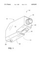
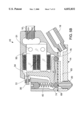
- FIG. 1 shows in perspective a glue head according to a preferred embodiment of the invention.
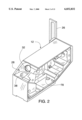
- FIG. 2 shows an actuator housing of the glue head, as an empty case without cover or components.
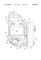
- FIG. 3 is a side elevation view showing the glue head with the actuator housing cover removed.
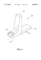
- FIG. 4 is a perspective view showing a valve actuator which resides in the actuator housing or case.
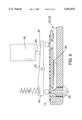
- FIG. 5 is a schematic elevation view, partially in section, illustrating the valve controlling glue flow in the glue head and demonstrating a principle of balanced forces on the valve actuator.
- FIG. 5A is a schematic diagram indicating forces acting on a glue valve actuator forming a part of the glue head.
- FIG. 5B is a schematic section view in elevation, again showing valve action.
- FIG. 6 is a view similar to FIG. 5, but showing a modified embodiment.
- FIG. 7 is a perspective view showing a glue housing or valve block from which glue is valved and dispensed and which is secured to the bottom side of the actuator housing.
- FIG. 8 is a side elevation view of the glue housing.
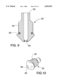
- FIG. 9 is an elevation view in section showing a nozzle component which is secured into the glue housing assembly.
- FIG. 10 is a perspective view of the nozzle component.
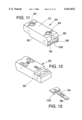
- FIG. 11 is a perspective view showing a modified valve block or glue casing to which a nozzle shutter is to be secured providing for a nozzle shutter to cover the nozzle when the glue head is not in use.
- FIG. 12 is another perspective view of the modified glue housing, showing its bottom side.
- FIG. 13 is a perspective view showing a shutter for assembly to the housing shown in FIGS. 11 and 12.
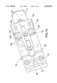
- FIG. 14 is a bottom perspective view of the glue head, showing the modified glue housing and the assembled nozzle shutter.
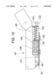
- FIG. 15 is a schematic elevation view, partially in section, showing the shutter assembly.
- FIG. 1 shows a glue head 10 according to the invention, comprised principally of an actuator housing 12 and a glue housing or valve block 14.
- the actuator housing has a side cover 13.
- On the actuator housing preferably oriented horizontally as shown, is a fitting 16 for electrical connection.
- a fitting 18 on the glue housing provides a connector for input of pressurized glue.
- Both the fittings 16 and 18 preferably are quick-disconnect type fittings; they preferably are oriented as shown, with the glue connector 18 angled upwardly about 25 to 30°, for reasons of space economy and so that the glue delivery hose (not shown) can angle up to the position of the electrical cable (not shown), and they can be secured together to extend to other parts of the machine on which the glue head 10 is mounted, specifically to a pressurized glue supply and to a controller for the glue heads on the machine.
- the glue housing or valve block 14 has a glue nozzle 20 extending from a side 22 which faces the paper, cardboard or other substrate on which glue is to be applied. Normally this is the bottom side of the glue head as mounted in a machine, but the terms “bottom”, “top”, “above”, “below”, “horizontal”, etc. are intended only for convenient reference in describing the preferred embodiment herein, and it is noted that because of the high velocity and clean stream of glue achieved by the glue head 10 of the invention, the head may be mounted in other orientations, so as to dispense glue horizontally or upwardly, if desired.
- the overall vertical height and "reach" of the nozzle 20 as compared to the back end 24 of the glue head, are often critical concerns in folding machines.
- the overall height of the glue head 10, including the nozzle 20, is only about 11/2" (38 mm). Its length, i.e. the length of the actuator housing 12, is about 2" (51 mm).
- the reach of the nozzle 20, forward from the back of the housing 12, where a mounting bracket 26 (FIG. 2) may be connected by securing into the reverse side of the housing 12 (not seen in FIGS. 1 and 2) preferably is about 13/4" (45 mm).
- FIG. 2 also shows the compactly formed actuator housing 12, which may be milled from an aluminum block.
- the actuator housing 12 is shown in FIG. 2 without the connected glue housing.
- the case or housing 12 is shown without its cover 13, and without internal components and external connectors and components.
- FIG. 2 shows a recessed area 28 at the upper front of the actuator casing.
- a manual purge button 30 has a shaft 31 which extends through an opening 32 in the casing, so that the inward end of the shaft 31 engages against a stem 34 of a valve actuator 36.
- the manual purge button 30, as explained further below, is used to push the actuator stem 34 to the right in FIG.
- FIG. 2 also reveals an opening 38 extending downward from the recess area 28, for assembly of and access to a compression spring 40, schematically indicated in dashed lines in FIG. 3.
- the spring 40 biases the actuator 36 toward valve closure, i.e. counterclockwise rotation as viewed in FIG. 3.
- FIG. 4 shows the actuator 36, according to one preferred embodiment of the invention.
- the actuator essentially comprises a pivot arm 42 with two ends 44 and 46.
- the end 44 has a spring seat recess 48.
- the actuator 36, or at least the stem portion 34, is formed of ferrous metal so as to be capable of attraction by a magnet.
- FIG. 3 shows an electromagnet 50 or solenoid as used to pull the actuator stem 34 to the right in FIG. 3, to open the valve. It is retained in the case 12 by fasteners 51.
- the device 50 can be a small electromagnet with power consumption as low as about 0.4 amp or 0.43 watt, due to the balancing of forces on the actuator 36 as discussed below.
- the electromagnet 50 actually remains cool to the touch during extended operation of the glue head.
- FIG. 3 also shows a manually operated electric purge switch 52.
- the switch 52 extending from a casing 53 comprises a spring loaded lever which makes momentary contact when pushed to effect pulsing of the actuator 36 and valve, for example at 50% duty cycle at 100 Hz.
- the electrical leads to the glue head include three leads, a ground, a control signal (activated by a remotely located controller to open and close the valve), and a line which continually supplies a pulsed signal, e.g., 100 Hz. Pushing the momentary switch 52 feeds the 100 Hz signal to the electromagnet 50 and disconnects the control line, which is normally connected.
- FIG. 5 shows the valve block or glue housing 14 in cross section and somewhat schematically indicates the action of the valve actuator 36 to open and close the valve and to balance forces on the actuator, with the assembly shown slightly exploded.
- FIGS. 7 and 8 also show the valve block.
- the spring 40 is a light compression spring, which may be only about 0.7 lb. force or less, acting on the actuator 36 in a direction to close the valve.
- the electromagnet or solenoid 50 when energized acts in opposition to the spring 40, and in accordance with the invention, is required to overcome essentially only the force of the spring 40 once the valve is opened, and a somewhat greater force when the valve is closed.
- the valve block 14 has screwed into it the nozzle component 20, as shown.
- This component includes a glue exit tube 56, the upper end 58 of which acts as a valve seat.
- the lower end has a small orifice 60, which is discussed below.
- the nozzle component is fitted into a bore 62, the lower portion of which is threaded, and the upper end of which extends out of the upper side of the block or housing 14.
- a glue plenum 63 communicates with the bore 62, around the outside and above the exit tube 56, the plenum receiving pressurized glue from an inlet end 66 to which the fitting 18 shown in FIG. 1 is connected. Glue thus surrounds the exit tube and valve seat 58 and when the valve is opened, flows down into the exit tube 56.
- the two bores 62 and 64 form first and second chambers, and a diaphragm 68 covers the two chambers.
- the diaphragm formed of a flexible, rubbery elastomeric material such as polyurethane, essentially comprises two separate diaphragms, one over each chamber, but assembly is simpler using a single strip of the rubbery material.
- the diaphragm strip 68 is permanently sealed against the two bores or chambers 62 and 64 when the glue housing or block 14 is secured to the upper, actuator housing 12.
- FIG. 7 shows the valve block with the fastener holes 73, the chamber bores 62, 64 and the plenum bore 63, all in dashed lines.
- FIG. 5 illustrates schematically, the ends 44 and 46 of the actuator's arm 42 press against the diaphragms 68.
- This is preferably via spherical balls 74 and 76 rather than by direct contact, having the advantage of an accurate round surface and one whose contact area is constantly renewed because of the ball's freedom of movement rotationally.
- Each ball is captured within a hole in the bottom of the actuator housing, the rear hole of which, for the ball 76, is visible in FIG. 2.
- the balls can be formed of a smooth, shape-stable and abrasion resistant material, such as carbide or nylon, with nylon being preferred because of its lower weight and cost.
- the balls 74 and 76 are also partially visible in FIG. 3, and the housing holes 78 are seen in FIG. 3 in dotted lines.
- the ball bearing spheres 74 and 76 are actuated by the arm 42 in opposition to one another.
- the light spring 40 pushes the end 44 of the arm with enough force that the ball 74 is pushed down against the diaphragm 68, which is displaced enough to be pushed and firmly seated against the valve seat 58 at the upper end of the exit tube 56.
- the other end 46 of the arm has pivoted upwardly and released at least some pressure of the ball 76 against the diaphragm, allowing the diaphragm to move toward its undeflected, natural position, approximately as shown in FIG. 5B.
- a 1 Diaphragm Area
- volume compensation Another benefit of the force compensation arrangement shown, as described earlier, is volume compensation. As one ball is pushed down, the other ball is allowed to rise, so that as glue is displaced into the first chamber, glue can expand outwardly in the second chamber. This balances the movement of glue in the plenum, and helps close the valve. On valve opening, volume compensation helps initially "crack" open the valve, helping overcome closure forces by displacing liquid toward the direction where more fluid is needed, i.e. by shifting glue toward the valve. The volume compensation acts to smooth the operation of the valve and the dispensing of glue so that hydraulic hammering is avoided and higher repetition rates can be achieved with smooth operation.
- FIG. 6 is similar to FIG. 5 but shows an alternative arrangement in which the actuator stem 34 of FIG. 5 is eliminated.
- a solenoid 80 has a plunger 82 which is pushed outwardly when the solenoid is energized.
- the plunger bears against the end 46 of the arm 42, having the same effect as the electromagnet 50 in FIG. 5.
- the advantage is that the valve actuation apparatus can have less mass and can occupy less space within the actuator housing 12. This affords space for onboard electronics, to allow distributed processing among the glue heads in the system. If the glue head is fitted with an optical sensor as to glue flow, the head can be intelligent in the sense of reporting when glue fails to flow as desired (as by an alarm). Moreover, the same stream of data from a controller could be fed to all glue heads serially, with each intelligent glue head taking only the instructions coded for that glue head.
- FIGS. 9 and 10 show the nozzle component 20.
- FIG. 9 indicates the jeweled orifice 83, preferably a ruby orifice, which is assembled into the tip of the nozzle component by swaging.
- the diameter of the orifice may be about 0.008 to 0.010 inch. Advantages of this highly polished and square-edged orifice structure are discussed above.
- the nozzle component's threads 84, for assembly into the valve block 14, are also shown in FIGS. 9 and 10, and an O-ring seal 85 is shown in FIG. 9.
- FIGS. 11-15 show a nozzle shutter which is preferably included on the valve head of the invention.
- FIG. 11 shows a modified valve block 90 which has additional volume via a lower extension 92, as compared to the valve block or glue housing 14 described above.
- the housing or block 90 shown of FIG. 11 is shown without any connected components, and is adapted to be secured to the same actuator housing shown and described above, via its upper surface 70. Its glue connection opening is shown at 66, and first and second hydraulic pressure chambers 62 and 64 are also shown, the same as those described for the valve block 14 above.
- the additional space in the block afforded by the extension 92 accommodates a nozzle shutter device 94 shown in FIG. 13, along with actuating pistons (seen in FIGS. 14-15), which are positioned in longitudinal bores 96 shown in FIG. 11.
- FIG. 14 shows the shutter device 94 as secured to the bottom or glue delivery side of the glue housing 90.
- the shutter device 94 has a nozzle closure tip 97, and when the shutter slides to the left as seen in FIG. 14, retained in place for sliding movement by a pair of fasteners 98, the closure tip moves over, contacts and covers the nozzle 20, particularly its orifice 60.
- the shutter device 94 is biased toward the closed direction (to the left in FIG. 14) by a pair of springs fitted in the ends of the bores 96 shown in FIG. 11, these compression springs 100 being schematically indicated in dashed lines in FIG. 14 and also shown in FIG. 15.
- the springs bear against legs or tabs 102 of the shutter device 94, and at their opposite ends they bear against plugs or retainers 103 (shown only in FIG. 15) fitted into the ends of the bores 96 (FIG. 11) after the shutter system is assembled.
- the shutter assembly illustrated is pneumatically actuated, although other forms of shutter can be used, such as glue-pressure hydraulically activated shutters.
- pneumatic pressure to retract the shutter and open the nozzle is received through a pneumatic fitting 104 at the back of the valve block.
- the air pressure is activated whenever the machine is to be active and dispensing glue, and is deactivated when there will be relatively long periods of inactivity for the glue heads, such as 15 minutes or one half hour.
- the air pressure is fed through an air inlet 106 of the block seen in FIG. 11, and through a connected longitudinal bore which passes beneath the glue plenum or conduit (seen at 63 in FIG. 5).
- the air pressure is then channeled from the air conduit 106 outwardly through a crossbore 107 which feeds the forward ends 107 of the bores 96, seen in FIG. 15.
- Small pistons 108 (FIG. 15) reside in the forward ends of those bores, and the pistons and connected rods 109 are pushed toward the back of the valve block (to the right in the drawings) when air pressure is fed into the block.
- the two pistons 108 one of which is also indicated in dashed lines in FIG. 14, push against the tabs 102 of the shutter device and overcome the compression springs 100 to retract the shutter.
- the pistons are not connected together laterally, so they "float” individually, avoiding binding in their cylinders.
- the pistons 108 can be very similar to a syringe piston, comprising a rubber seal or piston portion 108 to which is secured by snap-in connection a plastic piston rod 109, as shown in FIG. 15.
- the bore 96 is a cylinder for the piston.
- FIG. 14 shows that bores 73 through the block, similar to the bores 73 described above in reference to FIG. 7 for the valve block 14, are in the same positions in the valve block 90.
- the valve block 90 is secured to the actuator housing 12 via fasteners through these bores 73.
- the fastener openings 73 and the recessed fasteners in those openings do not interfere with the action of the pistons 108 or the shutter tabs 102.
Landscapes
- Coating Apparatus (AREA)
Priority Applications (2)
| Application Number | Priority Date | Filing Date | Title |
|---|---|---|---|
| US09/075,776 US6032832A (en) | 1998-05-11 | 1998-05-11 | Glue head |
| PCT/US1999/010364 WO1999058426A1 (en) | 1998-05-11 | 1999-05-11 | Glue head |
Applications Claiming Priority (1)
| Application Number | Priority Date | Filing Date | Title |
|---|---|---|---|
| US09/075,776 US6032832A (en) | 1998-05-11 | 1998-05-11 | Glue head |
Publications (1)
| Publication Number | Publication Date |
|---|---|
| US6032832A true US6032832A (en) | 2000-03-07 |
Family
ID=22127912
Family Applications (1)
| Application Number | Title | Priority Date | Filing Date |
|---|---|---|---|
| US09/075,776 Expired - Fee Related US6032832A (en) | 1998-05-11 | 1998-05-11 | Glue head |
Country Status (2)
| Country | Link |
|---|---|
| US (1) | US6032832A (und) |
| WO (1) | WO1999058426A1 (und) |
Cited By (16)
| Publication number | Priority date | Publication date | Assignee | Title |
|---|---|---|---|---|
| US6253972B1 (en) | 2000-01-14 | 2001-07-03 | Golden Gate Microsystems, Inc. | Liquid dispensing valve |
| US20060243758A1 (en) * | 2005-05-02 | 2006-11-02 | Parks Randolph S | Solenoid-operated fluid valve and assembly incorporating same |
| USD543564S1 (en) | 2005-06-29 | 2007-05-29 | Nordson Corporation | Hydraulic seal with a pivoting arm |
| US20090078787A1 (en) * | 2007-09-20 | 2009-03-26 | Wenbin Xu | Jet dispenser comprising magnetostrictive actuator |
| US20090294014A1 (en) * | 2008-06-03 | 2009-12-03 | Robatech Ag | Hot glue application device |
| US7694855B2 (en) | 2004-04-23 | 2010-04-13 | Nordson Corporation | Dispenser having a pivoting actuator assembly |
| US20120104053A1 (en) * | 2004-10-28 | 2012-05-03 | Nordson Corporation | Device for dispensing a heated liquid |
| US20140124600A1 (en) * | 2012-01-19 | 2014-05-08 | AdvanJet | Control method and apparatus for dispensing high-quality drops of high- viscosity material |
| US20140332569A1 (en) * | 2010-01-27 | 2014-11-13 | Robatech Ag | Electric application head for dispensing a free-flowing medium, and device comprising such an electric application head |
| US9346075B2 (en) | 2011-08-26 | 2016-05-24 | Nordson Corporation | Modular jetting devices |
| EP3708140A1 (en) | 2019-03-11 | 2020-09-16 | S & C Polymer Silicon- und Composite-Spezialitäten GmbH | Polymerizable bioactive compositions |
| US10913088B2 (en) * | 2017-08-08 | 2021-02-09 | Panasonic Intellectual Property Management Co., Ltd. | Coating nozzle head, and liquid-applying apparatus including the same |
| CN113117967A (zh) * | 2019-12-31 | 2021-07-16 | 泰州市龙洋木业有限公司 | 一种背板折叠涂胶机双通道涂胶头 |
| WO2022181736A1 (ja) * | 2021-02-24 | 2022-09-01 | 国立大学法人山形大学 | インクジェットヘッド、その製造方法、それを用いた半導体デバイスの製造方法、および印刷装置 |
| US11725377B1 (en) | 2022-01-21 | 2023-08-15 | Bradford A. Miley | Apparatus and method for a cycle siphon using a float operated magnetically controlling pivoting float valve for minimizing the build-up of gases |
| US12110886B2 (en) | 2020-02-28 | 2024-10-08 | Illinois Tool Works Inc. | Piston monitoring assembly |
Families Citing this family (1)
| Publication number | Priority date | Publication date | Assignee | Title |
|---|---|---|---|---|
| EP2667977B1 (de) * | 2011-01-25 | 2016-02-10 | Robatech AG | Hebelarmaufhängung für einen austragskopf |
Citations (7)
| Publication number | Priority date | Publication date | Assignee | Title |
|---|---|---|---|---|
| US4852800A (en) * | 1985-06-17 | 1989-08-01 | Flow Systems, Inc. | Method and apparatus for stablizing flow to sharp edges orifices |
| US4962871A (en) * | 1989-07-24 | 1990-10-16 | Valco Cincinnati, Inc. | Applicator utilizing high speed non-contact extrusion valve |
| US5405050A (en) * | 1993-10-27 | 1995-04-11 | Nordson Corporation | Electric dispenser |
| US5433351A (en) * | 1992-05-01 | 1995-07-18 | Misuzuerie Co., Ltd. | Controlled liquid dispensing apparatus |
| US5479352A (en) * | 1994-10-27 | 1995-12-26 | Golden Gate Microsystems, Inc. | System for accurately positioning operations on conveyed products |
| US5620142A (en) * | 1992-07-23 | 1997-04-15 | Elkas; Michael V. | Jeweled orifice fog nozzle |
| US5875922A (en) * | 1997-10-10 | 1999-03-02 | Nordson Corporation | Apparatus for dispensing an adhesive |
-
1998
- 1998-05-11 US US09/075,776 patent/US6032832A/en not_active Expired - Fee Related
-
1999
- 1999-05-11 WO PCT/US1999/010364 patent/WO1999058426A1/en active Application Filing
Patent Citations (7)
| Publication number | Priority date | Publication date | Assignee | Title |
|---|---|---|---|---|
| US4852800A (en) * | 1985-06-17 | 1989-08-01 | Flow Systems, Inc. | Method and apparatus for stablizing flow to sharp edges orifices |
| US4962871A (en) * | 1989-07-24 | 1990-10-16 | Valco Cincinnati, Inc. | Applicator utilizing high speed non-contact extrusion valve |
| US5433351A (en) * | 1992-05-01 | 1995-07-18 | Misuzuerie Co., Ltd. | Controlled liquid dispensing apparatus |
| US5620142A (en) * | 1992-07-23 | 1997-04-15 | Elkas; Michael V. | Jeweled orifice fog nozzle |
| US5405050A (en) * | 1993-10-27 | 1995-04-11 | Nordson Corporation | Electric dispenser |
| US5479352A (en) * | 1994-10-27 | 1995-12-26 | Golden Gate Microsystems, Inc. | System for accurately positioning operations on conveyed products |
| US5875922A (en) * | 1997-10-10 | 1999-03-02 | Nordson Corporation | Apparatus for dispensing an adhesive |
Non-Patent Citations (13)
| Title |
|---|
| hhs Leimauftrags Systeme brochure, Glue Application systems, 2 pp. * |
| hhs Leimauftrags-Systeme brochure, Glue Application systems, 2 pp. |
| hhs Vario Jet system, Vario valves, 1 pg. * |
| hhs Vario-Jet system, Vario valves, 1 pg. |
| MPC 16 Business Form Gluing System, 1 pg. * |
| Pafra Limited brochure, Direct Injection 24 Glue Gun, 2 pp. * |
| Pafra Limited brochure, Direct Injection Glue Gun, 2 pp. * |
| Pafra Limited brochure, Series 22MB glue gun, 2 pp. * |
| Pafra Limited brochure, Series 86 gluing stations, 2 pp. * |
| Pafra Limited brochure, Series 87 gluing stations, 2 pp. * |
| Pafra Limited brochure, Series 88 glue gun, 2 pp. * |
| Valco Cinn., 712/724 Glue Valve, 2 pg. brochure. * |
| Valco Cinn., Ltd., Pneumatically operated Glue vol. . . . , 1 pg. brochure. * |
Cited By (24)
| Publication number | Priority date | Publication date | Assignee | Title |
|---|---|---|---|---|
| US6253972B1 (en) | 2000-01-14 | 2001-07-03 | Golden Gate Microsystems, Inc. | Liquid dispensing valve |
| US7694855B2 (en) | 2004-04-23 | 2010-04-13 | Nordson Corporation | Dispenser having a pivoting actuator assembly |
| US20120104053A1 (en) * | 2004-10-28 | 2012-05-03 | Nordson Corporation | Device for dispensing a heated liquid |
| US8322575B2 (en) * | 2004-10-28 | 2012-12-04 | Nordson Corporation | Device for dispensing a heated liquid |
| USD546851S1 (en) | 2005-04-04 | 2007-07-17 | Nordson Corporation | Hydraulic seal with a pivoting arm |
| US20060243758A1 (en) * | 2005-05-02 | 2006-11-02 | Parks Randolph S | Solenoid-operated fluid valve and assembly incorporating same |
| USD543564S1 (en) | 2005-06-29 | 2007-05-29 | Nordson Corporation | Hydraulic seal with a pivoting arm |
| US20090078787A1 (en) * | 2007-09-20 | 2009-03-26 | Wenbin Xu | Jet dispenser comprising magnetostrictive actuator |
| US8056827B2 (en) * | 2007-09-20 | 2011-11-15 | Asm Assembly Automation Ltd | Jet dispenser comprising magnetostrictive actuator |
| US20090294014A1 (en) * | 2008-06-03 | 2009-12-03 | Robatech Ag | Hot glue application device |
| USD643054S1 (en) | 2008-06-03 | 2011-08-09 | Robatech, AG | Hot glue application device |
| US20140332569A1 (en) * | 2010-01-27 | 2014-11-13 | Robatech Ag | Electric application head for dispensing a free-flowing medium, and device comprising such an electric application head |
| US9346075B2 (en) | 2011-08-26 | 2016-05-24 | Nordson Corporation | Modular jetting devices |
| US9808825B2 (en) | 2011-08-26 | 2017-11-07 | Nordson Corporation | Modular jetting devices |
| US9808826B2 (en) | 2011-08-26 | 2017-11-07 | Nordson Corporation | Modular jetting devices |
| US10300505B2 (en) | 2011-08-26 | 2019-05-28 | Nordson Corporation | Modular jetting devices |
| US20140124600A1 (en) * | 2012-01-19 | 2014-05-08 | AdvanJet | Control method and apparatus for dispensing high-quality drops of high- viscosity material |
| US9254642B2 (en) * | 2012-01-19 | 2016-02-09 | AdvanJet | Control method and apparatus for dispensing high-quality drops of high-viscosity material |
| US10913088B2 (en) * | 2017-08-08 | 2021-02-09 | Panasonic Intellectual Property Management Co., Ltd. | Coating nozzle head, and liquid-applying apparatus including the same |
| EP3708140A1 (en) | 2019-03-11 | 2020-09-16 | S & C Polymer Silicon- und Composite-Spezialitäten GmbH | Polymerizable bioactive compositions |
| CN113117967A (zh) * | 2019-12-31 | 2021-07-16 | 泰州市龙洋木业有限公司 | 一种背板折叠涂胶机双通道涂胶头 |
| US12110886B2 (en) | 2020-02-28 | 2024-10-08 | Illinois Tool Works Inc. | Piston monitoring assembly |
| WO2022181736A1 (ja) * | 2021-02-24 | 2022-09-01 | 国立大学法人山形大学 | インクジェットヘッド、その製造方法、それを用いた半導体デバイスの製造方法、および印刷装置 |
| US11725377B1 (en) | 2022-01-21 | 2023-08-15 | Bradford A. Miley | Apparatus and method for a cycle siphon using a float operated magnetically controlling pivoting float valve for minimizing the build-up of gases |
Also Published As
| Publication number | Publication date |
|---|---|
| WO1999058426A1 (en) | 1999-11-18 |
Similar Documents
| Publication | Publication Date | Title |
|---|---|---|
| US6032832A (en) | Glue head | |
| US6161722A (en) | Liquid dispensing device and methods utilizing a magnetically coupled valve stem | |
| US10099238B2 (en) | Control method and apparatus for dispensing high-quality drops of high-viscosity materials | |
| US10300505B2 (en) | Modular jetting devices | |
| AU654215B2 (en) | Micro delivery valve | |
| EP2301677B1 (en) | A dispenser having a pivoting actuator assembly | |
| US8757511B2 (en) | Viscous non-contact jetting method and apparatus | |
| US4911405A (en) | Valve unit | |
| JP2598124B2 (ja) | 基板に液体接着剤を間欠塗布するためのバルブ | |
| US6915928B2 (en) | Fluid dispenser | |
| US4951917A (en) | Dynamic response time for electromagnetic valving | |
| US6655570B2 (en) | Constant volume valve for a combustion powered tool | |
| US5638920A (en) | Air tool lubricator | |
| JP2000193100A (ja) | 液体定量吐出バルブ | |
| US3476152A (en) | Multiple outlet valve | |
| CN111632796A (zh) | 一种无撞击式压电喷射点胶阀 | |
| JPH06505324A (ja) | 計量バルブ用シール構成 | |
| JPH1182785A (ja) | 計量 分配弁 | |
| JP6583895B2 (ja) | 液状物の吐出装置 | |
| JP2003080133A (ja) | マーキング装置 | |
| JP2581340Y2 (ja) | 高速印字用ガン | |
| EP0311267A1 (en) | Pneumatic actuator | |
| SU1655594A1 (ru) | Устройство дл маркировани изделий | |
| JP2556290Y2 (ja) | マーキング用ガン | |
| JPH02131164A (ja) | 高速印字用ガン |
Legal Events
| Date | Code | Title | Description |
|---|---|---|---|
| AS | Assignment |
Owner name: GOLDEN GATE MICROSYSTEMS, INC., CALIFORNIA Free format text: ASSIGNMENT OF ASSIGNORS INTEREST;ASSIGNORS:DORITY, DOUGLAS B.;DEVITO, THOMAS P.;REEL/FRAME:009172/0122 Effective date: 19980508 |
|
| REMI | Maintenance fee reminder mailed | ||
| LAPS | Lapse for failure to pay maintenance fees | ||
| FP | Lapsed due to failure to pay maintenance fee |
Effective date: 20040307 |
|
| AS | Assignment |
Owner name: GLUE SYSTEMS & MACHINERY INC., OHIO Free format text: ASSIGNMENT OF ASSIGNORS INTEREST;ASSIGNOR:GLUING MACHINERY & SYSTEMS, INC.;REEL/FRAME:034174/0123 Effective date: 20140916 Owner name: VALCO CINCINNATI, INC., OHIO Free format text: ASSIGNMENT OF ASSIGNORS INTEREST;ASSIGNOR:GLUE SYSTEMS & MACHINERY INC.;REEL/FRAME:034174/0645 Effective date: 20141114 |
|
| STCH | Information on status: patent discontinuation |
Free format text: PATENT EXPIRED DUE TO NONPAYMENT OF MAINTENANCE FEES UNDER 37 CFR 1.362 |