US6032751A - Electromechanical cross-drive steering transmission for tracklaying vehicles - Google Patents
Electromechanical cross-drive steering transmission for tracklaying vehicles Download PDFInfo
- Publication number
- US6032751A US6032751A US08/952,759 US95275997A US6032751A US 6032751 A US6032751 A US 6032751A US 95275997 A US95275997 A US 95275997A US 6032751 A US6032751 A US 6032751A
- Authority
- US
- United States
- Prior art keywords
- steering
- transmission
- radius
- radii
- steering transmission
- Prior art date
- Legal status (The legal status is an assumption and is not a legal conclusion. Google has not performed a legal analysis and makes no representation as to the accuracy of the status listed.)
- Expired - Fee Related
Links
Images


Classifications
-
- B—PERFORMING OPERATIONS; TRANSPORTING
- B62—LAND VEHICLES FOR TRAVELLING OTHERWISE THAN ON RAILS
- B62D—MOTOR VEHICLES; TRAILERS
- B62D11/00—Steering non-deflectable wheels; Steering endless tracks or the like
- B62D11/02—Steering non-deflectable wheels; Steering endless tracks or the like by differentially driving ground-engaging elements on opposite vehicle sides
- B62D11/06—Steering non-deflectable wheels; Steering endless tracks or the like by differentially driving ground-engaging elements on opposite vehicle sides by means of a single main power source
- B62D11/10—Steering non-deflectable wheels; Steering endless tracks or the like by differentially driving ground-engaging elements on opposite vehicle sides by means of a single main power source using gearings with differential power outputs on opposite sides, e.g. twin-differential or epicyclic gears
Definitions
- the invention concerns a cross-drive steering transmission for a tracklaying vehicle, in particular a cross-drive steering transmission having several fixed reduction gears.
- a difference of speed of the two driving chains is produced, whereby a turning radius appears in which the ratio of the inner radius to the outer radius corresponds to the speed ratio of the inner to the outer chain.
- cross-drive steering transmissions are used which superimpose the designed speed difference, between right and left chains, to the actual propulsion.
- cross-drive steering transmissions for presently known tracklaying vehicles, can be divided in two categories:
- hydrostatic or hydrodynamic steering transmission structures which work infinitely variably over the entire, or at least a large, range.
- the mechanical steering transmission advantageously stands out by its low cost, high efficiency, simple design and short reaction time, but has the disadvantage of possessing no infinitely variable range, or only a very small one, which results in stiff demands on the driver and relatively expensive safety devices against torque overloads.
- hydrostatic or hydrodynamic steering transmissions as result of their large, infinitely variable steering range, impose only slight demands on the driver and can be easily secured against torque overloads, but due to the complex design, the costs are elevated, the efficiency is low and the reaction time long.
- DE-A 36 19 055 has disclosed a mechanical cross-drive steering transmission with three radius ranges.
- Said transmission is comprised of a partial hydrostatic and a partial mechanical transmission.
- a zero shaft of the steering transmission cooperates with summarizing gears of the main transmission.
- the partial hydrostatic transmission is exclusively active
- the partial mechanical transmission is additionally active
- in a third fixed radius the partial mechanical transmission is exclusively active.
- the problem to be solved by the invention is to develop a mechanical cross-drive transmission so that, on one hand, the above described advantages are retained and, on the other, a large infinitely variable steering range results.
- a conventionally designed mechanical steering transmission which has an automatic steering radius switching means and a control wherein, according to the driver's steering radius input, switching is automatically produced by the control between the existing fixed steering radii in such a manner that the desired arc (with a corresponding radius) is approximated by a plurality of arc segments (with fixed radii).
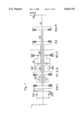
- FIG. 1 is a gear diagram of a steering transmission
- FIG. 2 is a diagram of the tracklaying vehicle transmission
- FIG. 3 is a hydraulic diagram
- FIG. 4 is an operation diagram
- FIG. 6 is a digital/analog change-over range
- FIG. 7 is a break down of steering angle
- FIGS. 8 and 9 show steering strategy
- FIG. 10 shows cornering
- FIG. 11 shows steering strategy
- FIG. 12 shows the steering transmission disconnection conditions
- FIG. 13 shows the steering transmission protection "reset” condition.
- FIG. 1 shows a gear diagram of the steering transmission as an example.
- the steering transmission is comprised essentially of a conventional, primarily driven three-radii steering transmission with three fixed radius reduction gears and an infinitely variable radius range for large steering radii.
- the infinitely variable radius is obtained by driven slippage in the clutch KR1/2/3 and controlled by a mechanically actuated, hydraulic steering control piston.
- FIG. 2 shows the diagram of the tracklaying transmission.
- Said steering transmission has been enlarged and has one speed sensor, respectively, on the steering transmission input, on the input shaft for the stabilizing clutches to the left and right, and on the steering transmission output for measuring the corresponding speeds.
- FIG. 3 shows a hydraulic diagram based on the system.
- the control of the steering transmission clutches KR1/2/3 and K3 and of the brake BRa/3 has been expanded by the solenoid valves M0, M1, M2 and M3 and by the control valves No. 11, 21, 31, 12, 22, 32.
- a rotation angle transmitter is installed, fastened to the transmission, upon the actuating shaft for the steering position transmitter for measuring the steering gear angle (driver's wish).
- FIG. 4 shows an operation diagram of the electronic transmission control. Relative to the system this has been expanded, according to hardware and software, by the operation periphery "steering transmission logic.” The appertaining hardware and the software has the function of processing the electric input signals issuing from the steering transmission or from the periphery and from the "driving transmission logic.”
- FIG. 5 shows the functional connection between the rotation angle on the steering wheel and the steering radius.
- the nominal turning radius of the driver is continuously communicated to the electronic control via the rotation angle transmitter on the actuating shaft of the steering control piston. From said information the position of the nominal turning radius, relative to the fixed radii made available by the steering transmission, is calculated and the control strategy is thus determined.
- the stabilizing clutches stab 13 li and stab -- re are controlled by the hydraulic steering control piston. Thereby a straight ahead driving is forced even under differing driving resistances.
- the clutch KR1/2/3 is likewise pulse-width modulated by the solenoid valve M1 and the valve 11 with a corresponding pulse width so that a pressure of about 0.8 to 1.0 bar appears.
- the clutch KR1/2/3 is thermally designed so that it can generate, with slippage, an infinitely variable range within certain limits. If the desired turning radius is within this range, the pressure of the clutch KR1/2/3, depending on the clutch differential speed, is raised by pulse-width modulation within the admissible pressure limits until the nominal turning radius corresponds to the actual turning radius--measured by the output speed of the steering transmission and of the output speed of the driving transmission. This is shown in FIGS. 6 and 7.
- the electronic control calculates with which partial turning radii from the adjacent fixed radii can be obtained the desired turning radius with the smallest admissible preset turning radius divergence.
- the tracklaying vehicle must here travel a turning radius which is between the fixed radii R1 and R2 made available by the steering transmission beginning at point 1 with the radius R -- nominal around the central point M -- nominal wherein the maximum divergence from desired radius, delta -- R -- max, may not be exceeded.
- the electronic control now calculates for the maximum admissible turning radius divergence, delta -- R -- max, the road portions for the fixed radii of the steering transmission and controls the corresponding steering transmission clutches or brakes.
- This strategy is also applied in cases where the nominal turning radius is smaller than the turning radius attainable, via the analog process, and larger than the largest fixed turning radius, as shown in FIG. 11.
- the maximum turning radius divergence is a function of the switching frequency of the steering transmission clutches.
- the minimum attainable turning radius divergence, delta -- R -- max, is limited by the thermal clutch stress of the steering transmission. This means, in turn, that the switching frequency of the clutches must be limited so that they lie within the limits of the switching frequency, as is at presently customary in manual control.
- the steering transmission control requests, with the signal "request n -- An -- steer" in the driving transmission control, a closure of the lock-clutch or a down-shift in the driving transmission (see FIG. 4).
- the digital range is disconnected, since there is no cross-driving speed from the driving transmission. That is, the steering clutches are controlled conventionally by the steering control piston. An infinitely variable rotating speed of the vehicle, via the steering wheel input, is thus available only in the analog range.
- the control system is designed so that parallel to the electronic control of the steering transmission clutches, the hydraulic steering control piston is mechanically controlled along and by the valves 12, 22 and 32, which are switched by the solenoid valve M0, is separated from the steering transmission clutches. It is thus ensured that, in case of electric interruption due to disconnection of solenoid valve M0, control of the steering transmission is automatically assumed by the hydraulic steering control piston.
- the electronic control in turn, is designed so that it checks itself continuously by plausibility criteria (FIG. 3).
- the signal "switch emergency steering" with the electronic driving transmission control requests a brief opening of the lock-up clutch in order to minimize an eventual turning radius jump during the switching to the emergency steering operation (FIG. 4).
- An overload of the steering transmission is prevented by designing the clutches of the steering transmission so that when a torque overload of the steering transmission occurs, the corresponding stabilizing clutch slips. At low speeds--at which the rotation point theoretically can lie between the chains and overloads can occur on account of very high turning resistances--said stabilizing clutches are continuously checked for slippage. If slippage is detected, the electronic control of the steering transmission first switches to a non-slip range so that, in the fixed driven vehicle, the torque first remains on the chains. After a strictly adjusted time has elapsed, the steering transmission is disconnected by the steering transmission control, by control of solenoid valve M0, and a stress-free engagement of the solenoid valves M1, M2 and M3.
- the steering wheel angle "alpha -- 1" refers to a steering wheel angle which ensures that the working range of the steering transmission is in the permanent non-slip range.
- the disconnection conditions, shown in FIG. 12, are steering transmission security devices to be interpreted as AND linkage of the different input parameters. By the "speed" input parameter, it is ensured that the security devices are switched to "stand-by" only at low speeds at which the steering transmission can be fundamentally exposed to a danger of overload. For considerations of general security, the steering transmission likewise is disconnected, in the neutral position of the selector switch, for the driving transmission after about 2.5 seconds has elapsed.
- the steering transmission is also disconnected when crossing the steering wheel angle "alpha -- 1." Since steering transmissions are primarily driven directly by the engine, the engine can be stalled with actuated steering during which the chains block in the case of panic braking. This can be prevented by disconnecting the steering transmission when driving below a specific engine speed "n -- 1.”
- FIG. 13 shows the reset conditions of the steering transmission protection which takes place depending on the position of the gear selector lever, of the steering wheel position and of the driving speed.
- a cross-drive steering transmission for steering a tracklaying vehicle thus contains at least two fixed mechanical reduction gears which act in accordance with at least two turning radii; an automatic steering radius switching means between the fixed reduction gears (fixed steering radii); a device for the driver inputting a desired steering radius; a control unit which, according to the driver's steering radius input, is switched among a plurality of the fixed steering radii and approximates the desired steering radius.
- the cross-drive steering transmission has, in addition, a directly infinitely variable steering range for large radii and, depending on preset turning radius, is switched by the control between directly infinitely variable steering range and graduated steering range.
- An advantageous embodiment of the cross-drive steering transmission can have, for example, three fixed reduction gears.
- a microprocessor is provided in the control which, with the aid of a corresponding program, calculates the desired turning radius from a plurality of adjacent, fixed turning radii while adhering to a preset maximum divergence and controls the steering transmission. It is also possible here to effect an optimation relative to a minimum number of switching operations.
- the clutches and/or brakes, in the steering transmission are designed so that the stabilizing clutches can only slip in case of overload.
- a cross-drive steering transmission which, for actuating the clutches, uses a speed-dependent basic frequency for the pulse-width modulation in the range of the digital steering.
- a constant switching frequency of the clutches results based on the covered path, that is, the maximum divergence from the theoretical turning course is thus independent of the driving speed.
- a cross-drive steering transmission which provides a slip control of the stabilizing clutches with a disconnection of the steering transmission via the solenoid valves of the radius clutches or with switching to the infinitely variable range of the first radius.
- the cross-drive steering transmission provides a mechanically actuated hydraulic steering control piston which is always passed along and, in case of interruptions in the electronic control, automatically passes over the control, via the steering transmission, to said hydraulic steering control piston.
- the cross-drive steering transmission according to the invention is adequate both for a primary (engine side) drive and for a secondary (output side) drive.
Landscapes
- Engineering & Computer Science (AREA)
- Chemical & Material Sciences (AREA)
- Combustion & Propulsion (AREA)
- Transportation (AREA)
- Mechanical Engineering (AREA)
- Control Of Transmission Device (AREA)
- Non-Deflectable Wheels, Steering Of Trailers, Or Other Steering (AREA)
Applications Claiming Priority (3)
| Application Number | Priority Date | Filing Date | Title |
|---|---|---|---|
| DE19521795A DE19521795A1 (de) | 1995-06-16 | 1995-06-16 | Elektro-mechanisches Überlagerungslenkgetriebe für ein Kettenfahrzeug |
| DE19521795 | 1995-06-16 | ||
| PCT/EP1996/002524 WO1997000190A1 (de) | 1995-06-16 | 1996-06-11 | Elektro-mechanisches überlagerungslenkgetriebe für ein kettenfahrzeug |
Publications (1)
| Publication Number | Publication Date |
|---|---|
| US6032751A true US6032751A (en) | 2000-03-07 |
Family
ID=7764446
Family Applications (1)
| Application Number | Title | Priority Date | Filing Date |
|---|---|---|---|
| US08/952,759 Expired - Fee Related US6032751A (en) | 1995-06-16 | 1996-06-11 | Electromechanical cross-drive steering transmission for tracklaying vehicles |
Country Status (6)
| Country | Link |
|---|---|
| US (1) | US6032751A (zh) |
| EP (1) | EP0832025B1 (zh) |
| KR (1) | KR100430490B1 (zh) |
| CN (1) | CN1060443C (zh) |
| DE (2) | DE19521795A1 (zh) |
| WO (1) | WO1997000190A1 (zh) |
Cited By (5)
| Publication number | Priority date | Publication date | Assignee | Title |
|---|---|---|---|---|
| US6389343B1 (en) | 2000-09-29 | 2002-05-14 | Caterpillar Inc. | Steering resistance device |
| US6755264B2 (en) * | 2000-11-21 | 2004-06-29 | Tuff Torq Corporation | Riding lawn mower |
| US20060283641A1 (en) * | 2003-09-26 | 2006-12-21 | Zf Friedrichshafen Ag | Electrical drive system for a vehicle with skid steering |
| US20080040006A1 (en) * | 2002-04-22 | 2008-02-14 | Volvo Construction Equipment Holding Sweden Ab | Device and method for controlling a machine |
| US20190337517A1 (en) * | 2018-05-01 | 2019-11-07 | Caterpillar Inc. | Transmission control or steering control based on one or more operating inputs associated with a vehicle |
Families Citing this family (3)
| Publication number | Priority date | Publication date | Assignee | Title |
|---|---|---|---|---|
| DE102006048737B3 (de) | 2006-10-12 | 2008-04-30 | Rheinmetall Landsysteme Gmbh | Antrieb für ein Kettenfahrzeug |
| CN108473158B (zh) * | 2015-11-16 | 2021-07-06 | 科特雷恩控股有限公司 | 履带式车辆再生转向差速器 |
| US10618506B2 (en) * | 2016-11-28 | 2020-04-14 | Allison Transmission, Inc. | Utilization of brakes and transmission system to affect steering of a vehicle and method thereof |
Citations (4)
| Publication number | Priority date | Publication date | Assignee | Title |
|---|---|---|---|---|
| DE1176002B (de) * | 1962-03-27 | 1964-08-13 | Renk Ag Zahnraeder | Einrichtung zum Lenken von Vollketten-fahrzeugen mit UEberlagerungslenkgetrieben |
| DE4341202A1 (de) * | 1993-12-03 | 1995-06-08 | Zahnradfabrik Friedrichshafen | Absicherung für ein Lenkgetriebe eines Kettenfahrzeugs |
| DE3619055C2 (de) * | 1985-06-15 | 1995-10-12 | Zahnradfabrik Friedrichshafen | Überlagerungslenkgetriebe für Gleiskettenfahrzeuge |
| US5569109A (en) * | 1993-01-28 | 1996-10-29 | Kabushiki Kaisha Komatsu Seisakusho | Geared steering device for crawler vehicle and control system therefor |
-
1995
- 1995-06-16 DE DE19521795A patent/DE19521795A1/de not_active Withdrawn
-
1996
- 1996-06-11 DE DE59603088T patent/DE59603088D1/de not_active Expired - Lifetime
- 1996-06-11 US US08/952,759 patent/US6032751A/en not_active Expired - Fee Related
- 1996-06-11 CN CN96194801A patent/CN1060443C/zh not_active Expired - Fee Related
- 1996-06-11 WO PCT/EP1996/002524 patent/WO1997000190A1/de active IP Right Grant
- 1996-06-11 EP EP96918683A patent/EP0832025B1/de not_active Expired - Lifetime
- 1996-06-11 KR KR1019970709232A patent/KR100430490B1/ko not_active IP Right Cessation
Patent Citations (4)
| Publication number | Priority date | Publication date | Assignee | Title |
|---|---|---|---|---|
| DE1176002B (de) * | 1962-03-27 | 1964-08-13 | Renk Ag Zahnraeder | Einrichtung zum Lenken von Vollketten-fahrzeugen mit UEberlagerungslenkgetrieben |
| DE3619055C2 (de) * | 1985-06-15 | 1995-10-12 | Zahnradfabrik Friedrichshafen | Überlagerungslenkgetriebe für Gleiskettenfahrzeuge |
| US5569109A (en) * | 1993-01-28 | 1996-10-29 | Kabushiki Kaisha Komatsu Seisakusho | Geared steering device for crawler vehicle and control system therefor |
| DE4341202A1 (de) * | 1993-12-03 | 1995-06-08 | Zahnradfabrik Friedrichshafen | Absicherung für ein Lenkgetriebe eines Kettenfahrzeugs |
Cited By (12)
| Publication number | Priority date | Publication date | Assignee | Title |
|---|---|---|---|---|
| US20050003919A1 (en) * | 1998-09-25 | 2005-01-06 | Toshiyuki Hasegawa | Riding lawn mower |
| US7059433B2 (en) * | 1998-09-25 | 2006-06-13 | Toshiyuki Hasegawa | Riding lawn mower |
| US20060196719A1 (en) * | 1998-09-25 | 2006-09-07 | Toshiyuki Hasegawa | Transmission for speed changing and steering of a vehicle |
| US6389343B1 (en) | 2000-09-29 | 2002-05-14 | Caterpillar Inc. | Steering resistance device |
| US6755264B2 (en) * | 2000-11-21 | 2004-06-29 | Tuff Torq Corporation | Riding lawn mower |
| US20080040006A1 (en) * | 2002-04-22 | 2008-02-14 | Volvo Construction Equipment Holding Sweden Ab | Device and method for controlling a machine |
| US7856301B2 (en) * | 2002-04-22 | 2010-12-21 | Volvo Construction Equipment Ab | Device and method for controlling a machine |
| US20060283641A1 (en) * | 2003-09-26 | 2006-12-21 | Zf Friedrichshafen Ag | Electrical drive system for a vehicle with skid steering |
| US7441618B2 (en) * | 2003-09-26 | 2008-10-28 | Zf Friedrichshafen Ag | Electrical drive system for a vehicle with skid steering |
| US20190337517A1 (en) * | 2018-05-01 | 2019-11-07 | Caterpillar Inc. | Transmission control or steering control based on one or more operating inputs associated with a vehicle |
| CN110422164A (zh) * | 2018-05-01 | 2019-11-08 | 卡特彼勒公司 | 基于与车辆相关联的一个或多个操作输入的变速器控制或转向控制 |
| US10850736B2 (en) * | 2018-05-01 | 2020-12-01 | Caterpillar Inc. | Transmission control or steering control based on one or more operating inputs associated with a vehicle |
Also Published As
| Publication number | Publication date |
|---|---|
| KR19990022766A (ko) | 1999-03-25 |
| EP0832025B1 (de) | 1999-09-15 |
| DE59603088D1 (de) | 1999-10-21 |
| CN1060443C (zh) | 2001-01-10 |
| WO1997000190A1 (de) | 1997-01-03 |
| DE19521795A1 (de) | 1996-12-19 |
| CN1187791A (zh) | 1998-07-15 |
| EP0832025A1 (de) | 1998-04-01 |
| KR100430490B1 (ko) | 2005-05-17 |
Similar Documents
| Publication | Publication Date | Title |
|---|---|---|
| EP0638455B1 (en) | Control system/method for engine brake assisted shifting | |
| JPS59109431A (ja) | 4輪駆動車の切換制御装置 | |
| AU742024B2 (en) | Steering control system for tracked vehicle | |
| CA2072079A1 (en) | Electrohydraulic control device for a drive train of a vehicle | |
| US5341893A (en) | Four wheel drive working vehicle having transmission clutches separately operable for driving right and left rear wheels | |
| US6032751A (en) | Electromechanical cross-drive steering transmission for tracklaying vehicles | |
| US6345674B1 (en) | Tracked vehicle steering control system with steering pump feedback | |
| EP0616918B1 (en) | Electrohydraulic control device for a drive train of a vehicle | |
| US20060122032A1 (en) | Driving system for off-road utility vehicle | |
| US6260642B1 (en) | Steering control system for tracklaying vehicle | |
| CA1217955A (en) | Overdrive system for a four-wheel drive vehicle | |
| GB2247290A (en) | An automatic-shift gear-change transmission with an automatically controlled overrunning clutch providing a hill brake. | |
| US5730677A (en) | Protection device for a steering transmission of a tracked vehicle | |
| JP2877252B2 (ja) | 変速機の急発進防止装置 | |
| JPH0411423B2 (zh) | ||
| JPH07149160A (ja) | 油圧駆動式装軌車両の発進時直進補正制御装置 | |
| JPS61184135A (ja) | パワ−トランスミツシヨンの操作部 | |
| JPS61184136A (ja) | 自動車用自動減速装置 | |
| WO2019224642A1 (en) | Self-propelled vehicle with four-wheel drive | |
| JPH0648223A (ja) | 自動車動力伝達装置 | |
| KR19980023551U (ko) | 센서에 의한 차량의 수동변속기 자동화 구조 | |
| JPH02299937A (ja) | 走行車両に於ける車速牽制制御装置 | |
| JPH02107862A (ja) | 走行車両の変速装置 | |
| JPH085351B2 (ja) | 油圧機械式変速・操向機を備えた車両の停止制御方法 | |
| KR19980026537A (ko) | 변속기 조작기구 제어 시스템 |
Legal Events
| Date | Code | Title | Description |
|---|---|---|---|
| AS | Assignment |
Owner name: ZF FRIEDRICHSHAFEN AG, GERMANY Free format text: ASSIGNMENT OF ASSIGNORS INTEREST;ASSIGNORS:LOICHINGER, WALTER;SORG, JOHANNES;REEL/FRAME:008982/0027;SIGNING DATES FROM 19970822 TO 19970825 |
|
| REMI | Maintenance fee reminder mailed | ||
| LAPS | Lapse for failure to pay maintenance fees | ||
| FP | Lapsed due to failure to pay maintenance fee |
Effective date: 20040307 |
|
| STCH | Information on status: patent discontinuation |
Free format text: PATENT EXPIRED DUE TO NONPAYMENT OF MAINTENANCE FEES UNDER 37 CFR 1.362 |