US6032722A - Strip casting - Google Patents

Strip casting Download PDF

Info

Publication number
US6032722A
US6032722A US09/292,882 US29288299A US6032722A US 6032722 A US6032722 A US 6032722A US 29288299 A US29288299 A US 29288299A US 6032722 A US6032722 A US 6032722A
Authority
US
United States
Prior art keywords
plates
rolls
pair
casting
side plates
Prior art date
Legal status (The legal status is an assumption and is not a legal conclusion. Google has not performed a legal analysis and makes no representation as to the accuracy of the status listed.)
Expired - Lifetime
Application number
US09/292,882
Inventor
Wayne Russell
Heiji Kato
Current Assignee (The listed assignees may be inaccurate. Google has not performed a legal analysis and makes no representation or warranty as to the accuracy of the list.)
Castrip LLC
Original Assignee
BHP Steel JLA Pty Ltd
IHI Corp
Priority date (The priority date is an assumption and is not a legal conclusion. Google has not performed a legal analysis and makes no representation as to the accuracy of the date listed.)
Filing date
Publication date
Application filed by BHP Steel JLA Pty Ltd, IHI Corp filed Critical BHP Steel JLA Pty Ltd
Assigned to BHP STEEL (JLA) PTY LTD., ISHIKAWAJIMA-HARIMA HEAVY INDUSTRIES COMPANY LIMITED reassignment BHP STEEL (JLA) PTY LTD. ASSIGNMENT OF ASSIGNORS INTEREST (SEE DOCUMENT FOR DETAILS). Assignors: RUSSELL, WAYNE, KATO, HEIJI
Application granted granted Critical
Publication of US6032722A publication Critical patent/US6032722A/en
Assigned to CASTRIP, LLC reassignment CASTRIP, LLC ASSIGNMENT OF ASSIGNORS INTEREST (SEE DOCUMENT FOR DETAILS). Assignors: BHP STEEL (JLA) PTY LTD, BROKEN HILL PROPRIETARY COMPANY LIMITED, THE, ISHIKAWAJIMA-HARIMA HEAVY INDUSTRIES LIMITED
Anticipated expiration legal-status Critical
Expired - Lifetime legal-status Critical Current

Links

Images

Classifications

    • BPERFORMING OPERATIONS; TRANSPORTING
    • B22CASTING; POWDER METALLURGY
    • B22DCASTING OF METALS; CASTING OF OTHER SUBSTANCES BY THE SAME PROCESSES OR DEVICES
    • B22D11/00Continuous casting of metals, i.e. casting in indefinite lengths
    • B22D11/06Continuous casting of metals, i.e. casting in indefinite lengths into moulds with travelling walls, e.g. with rolls, plates, belts, caterpillars
    • B22D11/0637Accessories therefor
    • B22D11/0648Casting surfaces
    • B22D11/066Side dams

Definitions

  • This invention relates to continuous casting of metal strip in a twin roll caster. It has particular, but not exclusive, application to the casting of steel strip.
  • molten metal is introduced between a pair of contra-rotated horizontal casting rolls which are cooled so that metal shells solidify on the moving roll surfaces and are brought together at the nip between them to produce a solidified strip product delivered downwardly from the nip between the rolls.
  • nip is used herein to refer to the general region at which the rolls are closest together.
  • the molten metal may be poured from a ladle into a smaller vessel or series of vessels from which it flows through a metal delivery nozzle located above the nip so as to direct it into the nip between the rolls, so forming a casting pool of molten metal supported on the casting surfaces of the rolls immediately above the nip and extending along the length of the nip.
  • This casting pool is confined between side plates or dams held in sliding engagement with end surfaces of the rolls so as to dam the two ends of the casting pool against outflow.
  • each pivot connection should preferably be disposed below the centre of effort of the outward forces applied to the respective side plate closure structure by the molten metal of the pool so as to cause the side closure structure to be rotationally biased by the outward pressure applied by the molten metal of the pool in such a direction that its lower part is biased inwardly of the rolls.
  • the present invention provides an improved arrangement in which the self-aligning rocking movements of the plates are permitted but the plates are constrained against the unwanted bodily rotation.
  • a twin roll strip caster for casting metal strip comprising a pair of generally horizontal casting rolls forming a nip between them;
  • metal delivery means to deliver molten metal into the nip between the casting rolls to form a casting pool of molten metal supported on the rolls;
  • the apparatus comprises side closure applicator means comprising a pair of side plate holders to hold the side plates, a pair of generally horizontally acting thrusters connected one to each of the side plate holders by pivot connections allowing tilting movements of the side plates, the thrusters are disposed to apply opposing inward closure forces to the side plates, and the pivot connections between the thrusters and the side plate holders are such as to permit the side plates to self-align with the roll ends by rocking movements both longitudinally and laterally of the rolls but to constrain the plates against rotation in the general planes of the plates.
  • the thrusters may comprise a pair of pressure fluid piston and cylinder units.
  • the thrusters may further comprise a pair of thruster bodies acted on by the piston and cylinder units and pivotally connected to the plate holders by said pivot connections.
  • each pivot connection defines a vertical pivot axis and a horizontal pivot axis which is perpendicular to the vertical pivot axis and extends transversely of the roll ends and is such that movement of the respective plate holder relative to the thruster body is confined to pivoting movements about said vertical and horizontal pivot axes.
  • FIG. 1 is a vertical cross-section through a twin roll caster
  • FIG. 2 is a plan view of the twin roll caster illustrated in FIG. 1;
  • FIG. 3 illustrates one of a pair of side plate applicators incorporated in the apparatus
  • FIG. 4 is a cross-section on the line 4-4 in FIG. 3.
  • the illustrated strip caster comprises a pair of twin casting rolls 1 forming a nip 2 between them.
  • Molten metal is supplied during a casting operation from a ladle (not shown) via a tundish 3, distributor 4 and a delivery nozzle 5 into the nip between the rolls 1 so as to produce a casting pool 6 of molten metal supported on the casting surfaces 12 of the rolls above the nip.
  • the ends of the casting pool are confined by a pair of refractory side closure plates 18 which are applied to stepped ends of the rolls by a pair of thrusters 21 comprising hydraulic cylinder units 22.
  • Tundish 3 is fitted with a stopper rod 7 actuable to allow the molten metal to flow from the tundish through an outlet nozzle 8 and a refractory shroud 9 into distributor 4.
  • Casting rolls 1 are water cooled so that shells solidify on the moving roller surfaces and are brought together at the nip 2 between them to produce a solidified strip product 19 at the roll outlet.
  • This product may be fed to a standard coiler (not shown).
  • each side plate 18 is mounted in holders 25 which are pivotally connected to the thrusters 21 so that the side plates can tilt about the pivot connections and the thrusters apply opposing forces through the pivots.
  • the pivot connections are provided in such a way that each side plate can rock longitudinally of the rolls by pivoting movement about a horizontal pivot axis transverse to the rolls and can rock laterally of the rolls by pivoting movement about a vertical pivot axis perpendicular to the horizontal pivot axis, the pivoting movement of the plates being confined to movements about those two specific axes so that planar rotation of the plates is prevented.
  • each side plate 18 is mounted in a side plate holder 25 which is pivotally connected by a horizontal pivot pin 26 and a pair of vertical pivot pins 28 to a thruster body 29 at the end of the respective thruster 21.
  • the vertical pivot pins 28 are fixed to thruster body 29 and fit into elongate slots 27 in the plate holder. Slots 27 are elongate in the direction longitudinal to the thruster 21 to leave small clearance gaps about the pivot pins 28 which permit limited rocking movement of the plate holder 25 about horizontal pin 26 longitudinally of the rolls.
  • Horizontal pivot pin 26 is also mounted on the thruster body 29 and engages an internally convex bearing 30 in the plate holder so that the plate holder 25 can rock laterally of the casting rolls about the vertical axis defined by the pivot pins 28.
  • the degree to which the plate holder is free to rock in this manner may be limited by engagement with stops on the thruster body 29.
  • Side plate holders 25 comprise side members 31 provided with inwardly facing channels to receive the side plates 18 and connected by stainless steel backing plates 32 connected to holder bodies 33 by studs 34 so as to leave an air gap between the backing plates and the holder body.
  • the air gap provides thermal insulation of the main body part of the plate holder and the outer parts which actually engage the side plates can readily be replaced when they become damaged or distorted through use.
  • the horizontal pivot pins 26 are located at such a height above the level of the nip between the casting rolls that the effect of the outward pressure on the side plates due to the molten metal in the casting pool is such as to rotationally bias the side plates about the pivots in such directions that their bottom ends are biased inwardly so as to produce increased sealing pressure at the bottom of the casting pool.
  • the arrangement permits tilting of the side plates so as to accommodate deformation of the casting roll end surfaces due to thermal expansion during casting and at the same time maintains a biasing action which increases the sealing forces at the bottom of the pool so as to counter-act the increased ferrostatic pressure at the bottom of the pool where there is accordingly the greatest tendency for leakage.

Abstract

Twin roll caster for casting metal strip comprises pair of horizontal casting rolls (1) on which to support a casting pool of molten metal. A pair of side plates (18) engage end surfaces of rolls (1) to form side confining closures for the casting pool. A pair of side plate holders (25) hold plates (18) and thrusters (21) apply opposing inward closure forces to side plates (18). Thrusters (21) are connected to side plate holders (25) by pivot connections defined by horizontal pivot pins (26) and vertical pivot pins (28) which permit side plates (18) to self-align with the roll ends by rocking movements both longitudinally and laterally of the rolls but to constrain the plates against rotation in the general planes of the plates.

Description

TECHNICAL FIELD
This invention relates to continuous casting of metal strip in a twin roll caster. It has particular, but not exclusive, application to the casting of steel strip.
In a twin roll caster molten metal is introduced between a pair of contra-rotated horizontal casting rolls which are cooled so that metal shells solidify on the moving roll surfaces and are brought together at the nip between them to produce a solidified strip product delivered downwardly from the nip between the rolls. The term "nip" is used herein to refer to the general region at which the rolls are closest together. The molten metal may be poured from a ladle into a smaller vessel or series of vessels from which it flows through a metal delivery nozzle located above the nip so as to direct it into the nip between the rolls, so forming a casting pool of molten metal supported on the casting surfaces of the rolls immediately above the nip and extending along the length of the nip. This casting pool is confined between side plates or dams held in sliding engagement with end surfaces of the rolls so as to dam the two ends of the casting pool against outflow.
It is very important to maintain good sealing engagement between the side plates and the end surfaces of the rolls since leakage can lead to the formation of severe defects at the edges of the cast strip product and the solidifying leaked metal can cause rapid destruction of the wear surfaces of the side plates and complete loss of sealing. This problem is exacerbated by deformation of the roll ends due to thermal expansion during casting. Parts of the roll passing through the pool during each rotation are heated progressively as they move from the upper regions of the pool to the nip. Consequently there is a tendency for the mid-parts of the roll in the region of the nip to expand outwardly more than the upper parts of the roll which deforms the roll end surface during casting. This can lead to excessive wear of the side plates adjacent the nip.
Australian Patent Application 34397/95 and corresponding U.S. Pat. No. 5,588,479 discloses a twin roll caster in which the side plates are held in a pair of structures which are pivotally connected to horizontally acting thrusters by pivot connections which allow tilting movements of the closure structures so as to enable the end plates to self-align with the ends of the rolls to accommodate end misalignments of the rolls either due to initial misalignment or deformation of the roll ends due to thermal expansion during casting. It is further disclosed that each pivot connection should preferably be disposed below the centre of effort of the outward forces applied to the respective side plate closure structure by the molten metal of the pool so as to cause the side closure structure to be rotationally biased by the outward pressure applied by the molten metal of the pool in such a direction that its lower part is biased inwardly of the rolls.
The construction disclosed in Australian Application 34397/95 and U.S. Pat. No. 5,588,479 has performed reasonably well in the casting of thin steel strip. However it has been found that the provision of a simple universally pivoting joint can lead to operational difficulties in some circumstances. Specifically, the simple pivot joint allows the plate not only to rock longitudinally and laterally of the rolls to provide the required self-alignment of the plates, but the plates are also free to rotate in their own general planes ie. they can each rotate about a horizontal axis extending longitudinally of the casting pool. It has been found that such rotational movements of the plates can cause them to expose different contact face areas to the ends of the rolls and if the plates are already worn they can have wear shoulders which upset the contact with the newly exposed faces resulting in poor contact, misalignment of the side dams and leakage of molten metal from the casting pool. The present invention provides an improved arrangement in which the self-aligning rocking movements of the plates are permitted but the plates are constrained against the unwanted bodily rotation.
DISCLOSURE OF THE INVENTION
According to the invention there is provided a twin roll strip caster for casting metal strip comprising a pair of generally horizontal casting rolls forming a nip between them;
metal delivery means to deliver molten metal into the nip between the casting rolls to form a casting pool of molten metal supported on the rolls;
a pair of side plates to engage end surfaces of the rolls whereby to form side confining closures for the casting pool; and
means to rotate the casting rolls in mutually opposite directions whereby to produce a cast strip delivered downwardly from the nip;
wherein the apparatus comprises side closure applicator means comprising a pair of side plate holders to hold the side plates, a pair of generally horizontally acting thrusters connected one to each of the side plate holders by pivot connections allowing tilting movements of the side plates, the thrusters are disposed to apply opposing inward closure forces to the side plates, and the pivot connections between the thrusters and the side plate holders are such as to permit the side plates to self-align with the roll ends by rocking movements both longitudinally and laterally of the rolls but to constrain the plates against rotation in the general planes of the plates.
The thrusters may comprise a pair of pressure fluid piston and cylinder units.
The thrusters may further comprise a pair of thruster bodies acted on by the piston and cylinder units and pivotally connected to the plate holders by said pivot connections.
Preferably, each pivot connection defines a vertical pivot axis and a horizontal pivot axis which is perpendicular to the vertical pivot axis and extends transversely of the roll ends and is such that movement of the respective plate holder relative to the thruster body is confined to pivoting movements about said vertical and horizontal pivot axes.
BRIEF DESCRIPTION OF THE DRAWINGS
In order that the invention may be more fully explained one particular embodiment will be described in detail with reference to the accompanying drawings in which:
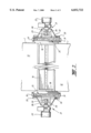
FIG. 1 is a vertical cross-section through a twin roll caster;
FIG. 2 is a plan view of the twin roll caster illustrated in FIG. 1;
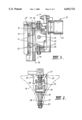
FIG. 3 illustrates one of a pair of side plate applicators incorporated in the apparatus; and
FIG. 4 is a cross-section on the line 4-4 in FIG. 3.
DETAILED DESCRIPTION OF THE PREFERRED EMBODIMENT
The illustrated strip caster comprises a pair of twin casting rolls 1 forming a nip 2 between them. Molten metal is supplied during a casting operation from a ladle (not shown) via a tundish 3, distributor 4 and a delivery nozzle 5 into the nip between the rolls 1 so as to produce a casting pool 6 of molten metal supported on the casting surfaces 12 of the rolls above the nip. The ends of the casting pool are confined by a pair of refractory side closure plates 18 which are applied to stepped ends of the rolls by a pair of thrusters 21 comprising hydraulic cylinder units 22. Tundish 3 is fitted with a stopper rod 7 actuable to allow the molten metal to flow from the tundish through an outlet nozzle 8 and a refractory shroud 9 into distributor 4.
Casting rolls 1 are water cooled so that shells solidify on the moving roller surfaces and are brought together at the nip 2 between them to produce a solidified strip product 19 at the roll outlet. This product may be fed to a standard coiler (not shown).
The illustrated twin roll caster as thus far described is of the kind which is illustrated and described in some detail in granted Australian Patent 664670 and U.S. Pat. No. 5,488,988 and reference may be made to those patents for appropriate constructional details which form no part of the present invention.
Side plates 18 are mounted in holders 25 which are pivotally connected to the thrusters 21 so that the side plates can tilt about the pivot connections and the thrusters apply opposing forces through the pivots. In accordance with the present invention the pivot connections are provided in such a way that each side plate can rock longitudinally of the rolls by pivoting movement about a horizontal pivot axis transverse to the rolls and can rock laterally of the rolls by pivoting movement about a vertical pivot axis perpendicular to the horizontal pivot axis, the pivoting movement of the plates being confined to movements about those two specific axes so that planar rotation of the plates is prevented.
As most clearly seen in FIGS. 3 and 4, each side plate 18 is mounted in a side plate holder 25 which is pivotally connected by a horizontal pivot pin 26 and a pair of vertical pivot pins 28 to a thruster body 29 at the end of the respective thruster 21. The vertical pivot pins 28 are fixed to thruster body 29 and fit into elongate slots 27 in the plate holder. Slots 27 are elongate in the direction longitudinal to the thruster 21 to leave small clearance gaps about the pivot pins 28 which permit limited rocking movement of the plate holder 25 about horizontal pin 26 longitudinally of the rolls.
Horizontal pivot pin 26 is also mounted on the thruster body 29 and engages an internally convex bearing 30 in the plate holder so that the plate holder 25 can rock laterally of the casting rolls about the vertical axis defined by the pivot pins 28. The degree to which the plate holder is free to rock in this manner may be limited by engagement with stops on the thruster body 29.
Side plate holders 25 comprise side members 31 provided with inwardly facing channels to receive the side plates 18 and connected by stainless steel backing plates 32 connected to holder bodies 33 by studs 34 so as to leave an air gap between the backing plates and the holder body. The air gap provides thermal insulation of the main body part of the plate holder and the outer parts which actually engage the side plates can readily be replaced when they become damaged or distorted through use.
The horizontal pivot pins 26 are located at such a height above the level of the nip between the casting rolls that the effect of the outward pressure on the side plates due to the molten metal in the casting pool is such as to rotationally bias the side plates about the pivots in such directions that their bottom ends are biased inwardly so as to produce increased sealing pressure at the bottom of the casting pool. The arrangement permits tilting of the side plates so as to accommodate deformation of the casting roll end surfaces due to thermal expansion during casting and at the same time maintains a biasing action which increases the sealing forces at the bottom of the pool so as to counter-act the increased ferrostatic pressure at the bottom of the pool where there is accordingly the greatest tendency for leakage.
Appropriate positioning of the pivots will depend on the diameter of the casting rolls, the height of the casting pool and thickness of the strip being cast. The manner in which correct positioning of the pivots can be determined is fully described in our Australian Patent Application 34397/95 and U.S. Pat. No. 5,588,479.

Claims (10)

We claim:
1. A twin roll strip caster for casting metal strip comprising a pair of generally horizontal casting rolls forming a nip between them;
metal delivery means to deliver molten metal inot the nip between the casting rolls to form a casting pool of molten metal supported on the rolls;
a pair of side plates to engage end surfaces of the rolls whereby to form side confining closures for the casting pool, each of said pair of side plates having a generally planar configuration defining a general plane of each plate; and
means to rotate the casting rolls in mutually opposite directions whereby to produce a cast strip delivered downwardly from the nip;
wherein the apparatus comprises side closure applicator means comprising a pair of side plate holders to hold the side plates, a pair of generally horizontally acting thrusters connected one to each of the side plate holders by pivot connections allowing tilting movements of the side plates, the thrusters are disposed to apply opposing inward closure forces to the side plates, and the pivot connections between the thrusters and the side plate holders are such as to permit the side plates to self-align with the roll ends by rocking movements both longitudinally and laterally of the rolls but to constrain the plates against rotation in the general planes of the plates.
2. A twin roll strip caster as claimed in claim 1, wherein the thrusters comprise a pair of pressure fluid piston and cylinder units.
3. A twin roll caster as claimed in claim 2, wherein the thrusters are a pair of hydraulic piston and cylinder units.
4. A twin roll caster as claimed in claim 2, wherein the thrusters further comprise a pair of thruster bodies acted on by the piston and cylinder units and pivotally connected to the plate holders by said pivot connections.
5. A twin roll caster as claimed in claim 4, wherein each pivot connection defines a vertical pivot axis and a horizontal pivot axis which is perpendicular to the vertical pivot axis and extends transversely of the roll ends and is such that movement of the respective plate holder relative to the thruster body is confined to pivoting movements about said vertical and horizontal pivot axes.
6. A twin roll caster as claimed in claim 5, wherein each plate holder is pivotally connected to a respective thruster body by a horizontal pivot pin defining said horizontal pivot axis and by a pair of vertical pivot pins defining said vertical pivot axis.
7. A twin roll caster as claimed in claim 6, wherein the vertical pivot pins are fixed to the respective thruster body and fit into elongate slots in the plate holder which slots extend longitudinally of the thruster to define clearance gaps about the vertical pivot pins permitting limited rocking movement of the plate holder about the horizontal pivot pin longitudinally of the rolls.
8. A twin roll caster as claimed in claim 6, wherein the said horizontal pivot pin is mounted on the thruster body and engages a convex bearing in the plate holder so that the plate holder can rock laterally of the casting rolls about the vertical pivot axis defined by the vertical pivot pins.
9. A twin roll caster as claimed in claim 6, wherein the horizontal pivot pins are located at such a height above the level of the nip between the casting rolls that the effect of the outward pressure on the side plates due to the molten metal in the casting pool is such as to rotationally bias the side plates about the pivots in such directions that their bottom ends are biased inwardly to produce increased sealing pressure at the bottom of the casting pool.
10. A twin roll caster as claimed in claim 1, wherein the side plate holders comprise side members provided with inwardly facing channels to receive the side plates said side plate holders further comprising backing plates at an inner part of said channels and holder bodies disposed at sides of said backing plates opposite sides on which said side plates are held, wherein said backing plates are connected to said holder bodies by studs so as to leave an air gap between said backing plates and said holder bodies.
US09/292,882 1998-05-04 1999-04-16 Strip casting Expired - Lifetime US6032722A (en)

Applications Claiming Priority (2)

Application Number Priority Date Filing Date Title
AUPP3315A AUPP331598A0 (en) 1998-05-04 1998-05-04 Strip casting
AUPP3315 1998-05-04

Publications (1)

Publication Number Publication Date
US6032722A true US6032722A (en) 2000-03-07

Family

ID=3807569

Family Applications (1)

Application Number Title Priority Date Filing Date
US09/292,882 Expired - Lifetime US6032722A (en) 1998-05-04 1999-04-16 Strip casting

Country Status (8)

Country Link
US (1) US6032722A (en)
JP (1) JP4208334B2 (en)
KR (1) KR100546867B1 (en)
AU (1) AUPP331598A0 (en)
DE (1) DE19919354B4 (en)
FR (1) FR2778126B1 (en)
GB (1) GB2337016B (en)
IT (1) IT1312203B1 (en)

Cited By (14)

* Cited by examiner, † Cited by third party
Publication number Priority date Publication date Assignee Title
US6497270B1 (en) * 1998-12-03 2002-12-24 Usinor Device for pressing a side wall in installation for continuous casting of metal strips between two drums against the planar surfaces of the drums
US20030062147A1 (en) * 2001-09-13 2003-04-03 Ak Properties, Inc. Method of continuously casting electrical steel strip with controlled spray cooling
US6655447B1 (en) * 1999-09-24 2003-12-02 Sms Demag Ag And Main Management Strip-casting machine for producing a metal strip
US6739382B2 (en) * 2001-08-29 2004-05-25 Danieli & C. Officine Meccaniche S.P.A. Device for lateral containment of liquid steel between crystallizing rolls of a casting machine for a steel strip
US20060102312A1 (en) * 2002-08-27 2006-05-18 Alfredo Poloni Metallic bath containment device between the crystallizing rollers of a continuous casting machine
US20070006990A1 (en) * 2003-07-01 2007-01-11 Sms Demag Aktiengesellschaft Method for operating a strip casting machine for producing a metal strip
US20070221358A1 (en) * 2006-03-24 2007-09-27 Nucor Corporation Long wear side dams
US20070267168A1 (en) * 2006-05-19 2007-11-22 Nucor Corporation Method and apparatus for continuously casting thin strip
US20090283240A1 (en) * 2006-03-24 2009-11-19 Nucor Corporation Side dam with insert
US20090314458A1 (en) * 2008-06-24 2009-12-24 Nucor Corporation Strip Casting Apparatus with Independent Delivery Nozzle and Side Dam Actuators
US20110024074A1 (en) * 2008-02-22 2011-02-03 Thyssenkrupp Nirosta Gmbh Method and Twin Roll Caster for the Production of Strip Cast from a Molten Metal
US8397794B2 (en) 2011-04-27 2013-03-19 Castrip, Llc Twin roll caster and method of control thereof
US10046384B2 (en) 2015-09-30 2018-08-14 Nucor Corporation Side dam with pocket
CN110039017A (en) * 2019-05-21 2019-07-23 一重集团大连工程技术有限公司 A kind of casting lateral seal

Families Citing this family (1)

* Cited by examiner, † Cited by third party
Publication number Priority date Publication date Assignee Title
DE102008010688B4 (en) * 2008-02-22 2019-03-28 Outokumpu Nirosta Gmbh Method and two-roll casting machine for producing cast from a molten metal strip

Citations (2)

* Cited by examiner, † Cited by third party
Publication number Priority date Publication date Assignee Title
US5588479A (en) * 1995-01-12 1996-12-31 Ishikawajima-Harima Heavy Industries Company Limited Strip casting
US5810070A (en) * 1996-01-05 1998-09-22 Ishikawajima-Harima Heavy Industries Company Limited Twin roll continuous caster

Family Cites Families (5)

* Cited by examiner, † Cited by third party
Publication number Priority date Publication date Assignee Title
JPH0749140B2 (en) * 1992-02-17 1995-05-31 三菱重工業株式会社 Twin-drum type continuous casting machine
FR2721844B1 (en) * 1994-06-30 1996-08-30 Usinor Sacilor METHOD AND DEVICE FOR CONTINUOUSLY CASTING THIN METAL PRODUCTS BETWEEN CYLINDERS
FR2721843B1 (en) * 1994-06-30 1996-08-30 Unisor Sacilor CONTINUOUS CASTING ARRANGEMENT BETWEEN CYLINDERS WITH APPLIED SIDE SHUTTER WALLS
AU693256B2 (en) * 1995-01-12 1998-06-25 Bluescope Steel Limited Strip casting
AUPP406798A0 (en) * 1998-06-12 1998-07-02 Bhp Steel (Jla) Pty Limited Strip casting apparatus

Patent Citations (2)

* Cited by examiner, † Cited by third party
Publication number Priority date Publication date Assignee Title
US5588479A (en) * 1995-01-12 1996-12-31 Ishikawajima-Harima Heavy Industries Company Limited Strip casting
US5810070A (en) * 1996-01-05 1998-09-22 Ishikawajima-Harima Heavy Industries Company Limited Twin roll continuous caster

Cited By (29)

* Cited by examiner, † Cited by third party
Publication number Priority date Publication date Assignee Title
US6497270B1 (en) * 1998-12-03 2002-12-24 Usinor Device for pressing a side wall in installation for continuous casting of metal strips between two drums against the planar surfaces of the drums
US6655447B1 (en) * 1999-09-24 2003-12-02 Sms Demag Ag And Main Management Strip-casting machine for producing a metal strip
US6739382B2 (en) * 2001-08-29 2004-05-25 Danieli & C. Officine Meccaniche S.P.A. Device for lateral containment of liquid steel between crystallizing rolls of a casting machine for a steel strip
US20030062147A1 (en) * 2001-09-13 2003-04-03 Ak Properties, Inc. Method of continuously casting electrical steel strip with controlled spray cooling
US6739384B2 (en) 2001-09-13 2004-05-25 Ak Properties, Inc. Method of continuously casting electrical steel strip with controlled spray cooling
US20060102312A1 (en) * 2002-08-27 2006-05-18 Alfredo Poloni Metallic bath containment device between the crystallizing rollers of a continuous casting machine
US7234509B2 (en) * 2002-08-27 2007-06-26 Danieli & C. Officine Meccaniche S.P.A. Metallic bath containment device between the crystallizing rollers of a continuous casting machine
US7337827B2 (en) * 2003-07-01 2008-03-04 Sms Demag Ag Method for operating a strip casting machine for producing a metal strip
US20070006990A1 (en) * 2003-07-01 2007-01-11 Sms Demag Aktiengesellschaft Method for operating a strip casting machine for producing a metal strip
US20090266504A1 (en) * 2006-03-24 2009-10-29 Nucor Corporation Long wear side dams
AU2007231532B2 (en) * 2006-03-24 2011-10-27 Bluescope Steel Limited Long wear side dams
US8042601B2 (en) * 2006-03-24 2011-10-25 Nucor Corporation Side dam with insert
CN101454095B (en) * 2006-03-24 2011-09-21 纽科尔公司 Long wear side dams
US7556084B2 (en) 2006-03-24 2009-07-07 Nucor Corporation Long wear side dams
US20070221358A1 (en) * 2006-03-24 2007-09-27 Nucor Corporation Long wear side dams
US20090283240A1 (en) * 2006-03-24 2009-11-19 Nucor Corporation Side dam with insert
US7975756B2 (en) * 2006-03-24 2011-07-12 Nucor Corporation Long wear side dams
US7975755B2 (en) 2006-05-19 2011-07-12 Nucor Corporation Method and apparatus for continuously casting thin strip
US20090159235A1 (en) * 2006-05-19 2009-06-25 Nucor Corporation Method and apparatus for continuously casting thin strip
US7503375B2 (en) 2006-05-19 2009-03-17 Nucor Corporation Method and apparatus for continuously casting thin strip
US20070267168A1 (en) * 2006-05-19 2007-11-22 Nucor Corporation Method and apparatus for continuously casting thin strip
US20110024074A1 (en) * 2008-02-22 2011-02-03 Thyssenkrupp Nirosta Gmbh Method and Twin Roll Caster for the Production of Strip Cast from a Molten Metal
US8453712B2 (en) 2008-02-22 2013-06-04 Outokumpu Nirosta Gmbh Method and twin roll caster for the production of strip cast from a molten metal
US20090314458A1 (en) * 2008-06-24 2009-12-24 Nucor Corporation Strip Casting Apparatus with Independent Delivery Nozzle and Side Dam Actuators
US8251127B2 (en) 2008-06-24 2012-08-28 Nucor Corporation Strip casting apparatus with independent delivery nozzle and side dam actuators
US8499820B2 (en) 2008-06-24 2013-08-06 Nucor Corporation Strip casting apparatus with independent delivery nozzle and side dam actuators
US8397794B2 (en) 2011-04-27 2013-03-19 Castrip, Llc Twin roll caster and method of control thereof
US10046384B2 (en) 2015-09-30 2018-08-14 Nucor Corporation Side dam with pocket
CN110039017A (en) * 2019-05-21 2019-07-23 一重集团大连工程技术有限公司 A kind of casting lateral seal

Also Published As

Publication number Publication date
JP4208334B2 (en) 2009-01-14
GB2337016A (en) 1999-11-10
KR19990087976A (en) 1999-12-27
DE19919354B4 (en) 2007-03-22
IT1312203B1 (en) 2002-04-09
DE19919354A1 (en) 1999-11-11
AUPP331598A0 (en) 1998-05-28
GB2337016B (en) 2003-02-19
KR100546867B1 (en) 2006-01-25
GB9909069D0 (en) 1999-06-16
JPH11314139A (en) 1999-11-16
FR2778126B1 (en) 2001-10-26
ITMI990839A1 (en) 2000-10-22
FR2778126A1 (en) 1999-11-05

Similar Documents

Publication Publication Date Title
US6032722A (en) Strip casting
US5588479A (en) Strip casting
US6296046B1 (en) Edge dam position control method and device in twin roll strip casting process
KR900002120B1 (en) Continuous casting apparatus of twin-drum type
US6237673B1 (en) Strip casting apparatus
US5871039A (en) Twin roll continuous caster
US6588492B1 (en) Strip casting apparatus
JP4227247B2 (en) Twin strip casting machine for metal strip casting
AU693256B2 (en) Strip casting
JPH02104447A (en) Apparatus for continuously casting sheet metal
RU2208497C2 (en) Side end wall for closing runner space of plant for continuous casting of metal strips between rolls and plant for casting with such side end wall
US7147035B2 (en) Strip casting apparatus
JP3071294B2 (en) Thin plate continuous casting equipment
AU703994B2 (en) Twin roll continuous caster
NO157489B (en) DEVICE FOR CONTINUOUS CASTING OF A METAL PRODUCT DIRECT FROM MELTED METAL.
AU743036B2 (en) Strip casting apparatus
JPH11347692A (en) Apparatus for casting metallic strip and side part demarcating plates for casting pool thereof

Legal Events

Date Code Title Description
AS Assignment

Owner name: ISHIKAWAJIMA-HARIMA HEAVY INDUSTRIES COMPANY LIMIT

Free format text: ASSIGNMENT OF ASSIGNORS INTEREST;ASSIGNORS:RUSSELL, WAYNE;KATO, HEIJI;REEL/FRAME:009905/0686;SIGNING DATES FROM 19990210 TO 19990305

Owner name: BHP STEEL (JLA) PTY LTD., AUSTRALIA

Free format text: ASSIGNMENT OF ASSIGNORS INTEREST;ASSIGNORS:RUSSELL, WAYNE;KATO, HEIJI;REEL/FRAME:009905/0686;SIGNING DATES FROM 19990210 TO 19990305

STCF Information on status: patent grant

Free format text: PATENTED CASE

AS Assignment

Owner name: CASTRIP, LLC, NORTH CAROLINA

Free format text: ASSIGNMENT OF ASSIGNORS INTEREST;ASSIGNORS:BHP STEEL (JLA) PTY LTD;ISHIKAWAJIMA-HARIMA HEAVY INDUSTRIES LIMITED;BROKEN HILL PROPRIETARY COMPANY LIMITED, THE;REEL/FRAME:012428/0860

Effective date: 20011012

FPAY Fee payment

Year of fee payment: 4

FPAY Fee payment

Year of fee payment: 8

FPAY Fee payment

Year of fee payment: 12