US6032568A - Means for controlling the muzzle velocity of a projectile - Google Patents
Means for controlling the muzzle velocity of a projectile Download PDFInfo
- Publication number
- US6032568A US6032568A US08/959,989 US95998997A US6032568A US 6032568 A US6032568 A US 6032568A US 95998997 A US95998997 A US 95998997A US 6032568 A US6032568 A US 6032568A
- Authority
- US
- United States
- Prior art keywords
- muzzle velocity
- projectile
- gun
- controlling
- discharge
- Prior art date
- Legal status (The legal status is an assumption and is not a legal conclusion. Google has not performed a legal analysis and makes no representation as to the accuracy of the status listed.)
- Expired - Fee Related
Links
Images
Classifications
-
- F—MECHANICAL ENGINEERING; LIGHTING; HEATING; WEAPONS; BLASTING
- F41—WEAPONS
- F41A—FUNCTIONAL FEATURES OR DETAILS COMMON TO BOTH SMALLARMS AND ORDNANCE, e.g. CANNONS; MOUNTINGS FOR SMALLARMS OR ORDNANCE
- F41A19/00—Firing or trigger mechanisms; Cocking mechanisms
- F41A19/58—Electric firing mechanisms
-
- F—MECHANICAL ENGINEERING; LIGHTING; HEATING; WEAPONS; BLASTING
- F41—WEAPONS
- F41G—WEAPON SIGHTS; AIMING
- F41G3/00—Aiming or laying means
- F41G3/12—Aiming or laying means with means for compensating for muzzle velocity or powder temperature with means for compensating for gun vibrations
Definitions
- This invention relates to a means of controlling the muzzle velocity of a projectile, in particular to a means for correcting the muzzle velocity of a projectile fired from an artillery gun.
- European Patent specification No. 0 138 942 discloses a course correction system for projectiles which measures the launch velocity, determines the impact point and relays a signal to the munition to activate a braking means on the projectile at an appropriate point.
- Such braking systems however require the projectile to house the braking means and also the sophisticated communication equipment reducing the available payload volume and increasing the cost of each shell. Further, such correction means always has a negative effect on range.
- a means for controlling the muzzle velocity of a gun launched projectile comprising
- a sensor means capable of measuring a parameter related to the muzzle velocity of a projectile
- a control means capable of controlling a parameter related to the muzzle velocity of a projectile
- an electrothermal energy unit capable of discharging a fixed amount of electrothermal energy into a gun barrel upon receipt of a trigger signal from said control means
- said control means introduces a delay into the transmission of the trigger signal to said electrothermal energy unit, said delay being dependent upon the measured parameter such that discharge of said fixed amount of electrothermal energy causes the projectile to achieve a controlled muzzle velocity.
- Discharging electrothermal energy into the gun barrel heats the propellant gases causing an increased pressure in the barrel and therefore increases the force on the projectile.
- the burning rate of the propellant is also enhanced further increasing the force on the projectile.
- the delay introduced will be such that discharge occurs earlier for a slower round than for a faster round.
- a small delay between measurement of the parameter related to the muzzle velocity and energy discharge means that the energy is discharged early along the shell's passage along the bore whereas for a relatively fast round, having a longer delay, the projectile will be nearer the muzzle when the energy is discharged.
- Discharging the energy earlier for the slower round ensures that the increased force due to discharge will have longer to act on the projectile than had it been a faster round.
- the increase in muzzle velocity due to discharge of electrothermal energy will be greater for the slower round than for the faster round and in general the discharge of electrothermal energy will cause the muzzle velocities of each round to tend toward the same value.
- the electrothermal energy unit can be relatively simple and the amount of energy discharged can be quite precise. Also the time delay introduced can be controlled to a high degree of accuracy, say by using electronic techniques.
- control means may be capable of predicting the muzzle velocity of a projectile from the measured parameter and the delay introduced into transmission of the trigger signal to the electrothermal energy unit is dependent upon the predicted muzzle velocity.
- control means is programmed with a preset value of a desired muzzle velocity and is adapted to introduce a time delay to the discharge of the electrothermal energy unit such that discharge of the electrothermal energy unit, in use, causes the actual muzzle velocity of the projectile to tend toward the preset value.
- the control means may also be adapted such that if the predicted muzzle velocity is equal to or greater than the preset value then the control means does not generate a trigger signal such that the electrothermal energy unit does not discharge.
- the preset value of a muzzle velocity can be chosen so as to be at the top end of the range of unadjusted muzzle velocities so that some rounds, having predicted velocities near the top end of the expected range do not cause the electrothermal energy unit to discharge whereas the rounds having a predicted muzzle velocity near the bottom end of the expected range have a short delay before discharge.
- a value towards the top or above the expected range of muzzle velocities is chosen so that there will be very few projectiles having a muzzle velocity greater than the preset value.
- the electrothermal energy unit can be quite small.
- the electrothermal energy unit may be adapted such that the fixed amount of electrothermal energy discharged can be set prior to charging.
- the electrothermal energy unit and control means are adapted such that the amount of energy to be discharged can be controlled via the control means.
- a range of shells and charges would have their muzzle velocities controlled purely by control of the delay introduced, in some instances it may be necessary to control the amount of energy discharged.
- the control means could be programmed with data about a range of different types of round and charge types and could adjust the amount of energy accordingly when a different combination is used. Precision could then be achieved by discharging the same amount of energy for a given charge and altering the amount when a different charge is used. Further, the amount of energy discharged could be adjusted prior to firing to account for differences in intended range.
- the same fixed amount of energy could be discharged for several rounds of the same type when the gun system was being used as an accurate relatively short range weapon and the amount increased when the gun is used in an extended range mode.
- the control means could be programmed with a range of preset values of muzzle velocities corresponding to a range of energies to be discharged. The amount of energy to be discharged is altered prior to charging in order to avoid real time switching of high voltage components.
- the electrothermal energy unit conveniently comprises a pulsed power supply in order to facilitate a quick and precise discharge. It will also comprise a means for introducing the energy to the propellant gases. Means for introducing the energy to the propellant gases, such as plasma injectors or exploding wires, are well known in the art and it will be readily apparent to a worker in the field how they could be applied to this system.
- the electrothermal energy unit may be adapted to supply a single energy discharge, on receipt of the trigger signal or alternatively the electrothermal energy unit could be used to ignite the propellant charge and then supply a later discharge upon receipt of the trigger signal.
- a convenient parameter to measure is the movement of the projectile within the barrel.
- the movement of the projectile within the barrel is related to the final muzzle velocity and can be measured by direct methods.
- a simple means of monitoring the movement of a projectile down a barrel is to have at least two sensors located on a gun barrel, each sensor being capable of detecting passage of a projectile. The passage of the projectile can then be detected in at least two places and the time delay between the registering of the passage of a projectile by each of the sensors gives an indication of the progress of the projectile.
- the control means can then predict the muzzle velocity from the times taken for passage of a projectile past each of the sensors.
- the sensors may usefully be strain gauges adapted so as to be in contact with the gun barrel. Strain gauges affixed to a gun barrel can measure the slight expansion of the barrel caused by the travel of a projectile down the gun barrel. Strain gauges offer a simple and inexpensive method of determining passage of a projectile and may be easily attached to a gun barrel. Also, the level of strain reached can be set at any threshold value allowing for a simple signal processing arrangement.
- the gauges may either be adapted to lie parallel to the axis of the barrel or alternatively may be adapted to lie along at least part of the circumference of the gun barrel.
- the apparatus also comprises a means for measuring the actual muzzle velocity of a projectile and the control means is adapted such that the time delay introduced into generation of the trigger signal is also dependent upon the actual muzzle velocity measured, and the time delay introduced, for the previous round or rounds.
- the effect of the energy discharge can be gauged.
- the delay introduced for a predicted muzzle velocity can be compared with the actual muzzle velocity measured to ensure that the delay introduced leads to a consistent muzzle velocity for all rounds.
- the addition of an actual muzzle velocity measuring means also increases the effectiveness of a battery of guns each having a means for controlling the muzzle velocity as individual variations from gun to gun can be accounted for.
- the way of measuring the actual muzzle velocity may comprise a radar means. Radar devices for measuring the velocities of gun launched projectiles are well known in the art and are relatively inexpensive whilst being reliable and accurate.
- a further aspect of the present invention is the provision of a gun system having a means for controlling the muzzle velocity of a projectile as described above.
- Such a gun system would have a precise muzzle velocity for rounds of the same type which would substantially reduce the deviations in range and increase the precision of the system without requiring expensive and complex guided munitions. Also, several such gun systems could be more efficiently used in a battery to provide accurate fire. Further the gun could be used as an extended range gun having an acceptable dispersion.
- the gun system may utilise sensors capable of detecting the movement of a projectile within the barrel as described above, in which case the sensors are affixed to the outside of the barrel and separated along the axis of the gun barrel.
- the sensor nearest to the breech of the gun is located just after the commencement of barrel rifling.
- time delay is dependent upon said measured parameter such that discharge of said fixed amount of electrothermal energy causes the projectile to achieve a controlled muzzle velocity.
- the method comprises the additional step, after measuring the parameter related to the muzzle velocity of a projectile, of predicting the muzzle velocity of the projectile from the measured parameter and the time delay before discharge of the electrothermal energy is dependent upon the predicted muzzle velocity.
- the time delay is such that discharge of the electrothermal energy causes the actual muzzle velocity of the projectile to tend towards a preset value.
- the parameter measured may be the movement of the projectile within the barrel.
- the actual muzzle velocity of a projectile may also be measured.
- the time delay introduced before discharge of the fixed amount of electrothermal energy may therefore also depend upon the actual muzzle velocity measured, and time delay introduced, for a previous round or rounds.
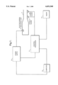
- FIG. 1 shows a schematic of an embodiment of the invention utilising strain gauges as applied to an artillery gun.
- the breech end of a gun barrel 2 has two strain gauges 4, 6 attached to the outside of the barrel 2.
- the strain gauges 4, 6 are connected to a control processor 8, which is itself connected to a pulsed power supply 10.
- the propellant charge of a shell is ignited either by standard techniques or by discharge from the pulsed power supply 10. Ignition of the propellant charge produces propellant gases, propelling the shell down the barrel 2. Movement of the shell down the barrel 2 causes the barrel to expand at that point due to passage of the shell's driving band. This expansion is detected by both gauges 4 and 6 as an increase in the strain level past some threshold value.
- strain reached is unimportant, as detection of the passage of the shell is all that is required, so long as a good signal to noise ratio is achieved.
- gauges may be aligned parallel to the barrel or alternatively may be disposed as part of a loop around the barrel. The times at which each strain gauge detects passage of the shell are recorded by the control processor 8, clearly giving an indication of what the muzzle velocity would be in that a faster round will have a shorter time interval between the shell passing the first and second gauges.
- the control processor 8 determines the time delay required before discharge, via the electrothermal discharge unit 16, of the electrical energy from the pulsed power unit 10 using, for example, either a suitable algorithm or a look up table.
- the control processor is itself controlled by a fire control computer 12.
- the fire control computer 12 can be programmed with the type of charge and round to be fired and alters the time delay introduced by the control processor 8 accordingly. Other factors such as the prevailing environmental conditions or a specifically required value of muzzle velocity could also be programmed into the fire control computer 12 which would then alter the time delay introduced by the control processor 8.
- the amount of energy to be discharged by the pulsed power unit 10 may also be controlled by the fire control computer 12 and is set by switching charge voltages, inductors and the like, prior to firing.
- the control processor 8 counts the delay required and then sends a trigger signal to the pulsed power unit 10 to discharge. If the shell's propellant charge was ignited by standard means then the pulsed power unit charges prior to firing and then discharges the preset amount of energy on receipt of the trigger signal. However, if the propellant charge was ignited by a discharge of electrothermal energy then the pulsed power unit includes a pulse forming network which generates a three part pulse. The first part would be a discharge that ignites the propellant charge. The second is fed through a large inductor causing a long sustained pulse to occur that maintains the current path in the discharge device as the shell starts its travel down the bore. The final part is the discharge of the required energy to control the muzzle velocity of the shell and is discharged upon receipt of the trigger signal.
- the pulsed power unit may either store the energy for the next round or may discharge through an alternative route.
- the pulsed power unit may contain capacitors as a storage medium or may employ other storage devices such as compensated pulsed alternators or disc alternators. Capacitors would be discharged if another round were not to be fired in the near future in order to avoid damage to the capacitor. Alternator devices however could store the energy for long periods.
- Discharge of the electrothermal energy heats the propellant gases thus increasing the pressure in the barrel and also speeding up the combustion process.
- the resulting increase in force on the shell increases the acceleration and therefore the actual muzzle velocity of the shell.
- the time delay before discharge controls the effectiveness of the discharge.
- a shell near the end of its travel will only experience the increased force for a short time before exiting the barrel and so will gain a relatively small increase in its muzzle velocity.
- a discharge that occurs soon after the shell has passed the second strain gauge 6 will gain far more energy and its increase in muzzle velocity will be corresponding higher.
- the actual muzzle velocity is measured by a muzzle velocity radar 14 as is well known in the art. This value of measured muzzle velocity is then fed back to the control processor 8 to allow the intended and achieved muzzle velocities to be compared with the time delay introduced.
- the control processor 8 can integrate the actual measured velocities to compensate for any deviations from the expected velocity by using, for example, a neural network or Kalman filter. In this way deviation from the intended muzzle velocity such as could be caused by long term changes such as gun wear or other ageing processes can be corrected by altering the delay times.
- the control processor 8 can record all the data and constantly update and compensate the delay times to account for any long term changes which may occur during the life of the gun. In addition, the control processor will be able to maintain a log of the gun's entire operational life.
- the range of time delays before discharge for a fast and slow round should be as great as possible.
- discharge should occur as early along the shells travel down the barrel as possible.
- the strain gauges, control processor and pulsed power unit are therefore chosen to have fast response times. How early discharge can be effected is then determined by the positioning of the gauges 4, 6 and in particular the second gauge 6. During the early stages of travel however, the shell's acceleration occurs in an irregular fashion and a prediction of muzzle velocity based on the progress of the shell during the early stages is prone to inaccuracies.
- the first strain gauge 4 is therefore located after the chamber shoulder and commencement of rifling.
- the separation of the strain gauges is therefore chosen so as to give an accurate indication of the time difference between the shell passing each strain gauge but is not so large so that discharge of the electrothermal energy can only occur in the latter stages of the shells travel.
Landscapes
- Engineering & Computer Science (AREA)
- General Engineering & Computer Science (AREA)
- Aiming, Guidance, Guns With A Light Source, Armor, Camouflage, And Targets (AREA)
- Toys (AREA)
Applications Claiming Priority (2)
| Application Number | Priority Date | Filing Date | Title |
|---|---|---|---|
| GB9622615A GB2318856B (en) | 1996-10-30 | 1996-10-30 | Means for controlling the muzzle velocity of a projectile |
| GB9622615 | 1996-10-30 |
Publications (1)
| Publication Number | Publication Date |
|---|---|
| US6032568A true US6032568A (en) | 2000-03-07 |
Family
ID=10802186
Family Applications (1)
| Application Number | Title | Priority Date | Filing Date |
|---|---|---|---|
| US08/959,989 Expired - Fee Related US6032568A (en) | 1996-10-30 | 1997-10-29 | Means for controlling the muzzle velocity of a projectile |
Country Status (6)
| Country | Link |
|---|---|
| US (1) | US6032568A (fr) |
| EP (1) | EP0840087B1 (fr) |
| DE (1) | DE69709291T2 (fr) |
| GB (1) | GB2318856B (fr) |
| IL (1) | IL122060A (fr) |
| ZA (1) | ZA979621B (fr) |
Cited By (7)
| Publication number | Priority date | Publication date | Assignee | Title |
|---|---|---|---|---|
| US6805055B1 (en) | 2003-06-25 | 2004-10-19 | Gamma Recherches & Technologies Patent Sa | Plasma firing mechanism and method for firing ammunition |
| US20070084102A1 (en) * | 2003-05-02 | 2007-04-19 | O'dwyer James M | Combined electrical mechanical firing systems |
| US20090289619A1 (en) * | 2008-05-21 | 2009-11-26 | Rheinmetall Air Defence Ag | Apparatus and method for measurement of the muzzle velocity of a projectile or the like |
| WO2012068669A1 (fr) * | 2010-11-22 | 2012-05-31 | Drs Technologies Canada, Ltd. | Capteur de vitesse initiale |
| CN111814387A (zh) * | 2020-06-11 | 2020-10-23 | 中国兵器科学研究院 | 一种破片初速确定方法和装置及电子设备 |
| CN114777566A (zh) * | 2022-04-14 | 2022-07-22 | 中国人民解放军陆军工程大学 | 一种增药式火炮初速连续化装置及控制方法 |
| RU2780667C1 (ru) * | 2021-11-30 | 2022-09-28 | Федеральное государственное военное казённое образовательное учреждение высшего профессионального образования "Военная академия Материально-технического обеспечения имени генерала армии А.В. Хрулева" Министерства обороны Российской Федерации | Адаптивное устройство измерения параметров движения снаряда на этапе внутренней баллистики |
Families Citing this family (5)
| Publication number | Priority date | Publication date | Assignee | Title |
|---|---|---|---|---|
| DE10352047A1 (de) | 2003-11-07 | 2005-06-16 | Oerlikon Contraves Pyrotec Ag | Vorrichtung zur Bestimmung der Geschossgeschwindigkeit, insbesondere im Mündungsbereich eines Waffenrohres |
| DE102006058375A1 (de) | 2006-12-08 | 2008-06-12 | Oerlikon Contraves Ag | Verfahren zur Messung der Mündungsgeschwindigkeit eines Projektils oder dergleichen |
| DE102007044732A1 (de) | 2007-09-18 | 2009-04-02 | Oerlikon Contraves Ag | Verfahren und Vorrichtung zur Erhöhung der Treffgenauigkeit einer insbesondere zeitgesteuerten Munitionszerlegung |
| SE533046C2 (sv) * | 2008-04-01 | 2010-06-15 | Bae Systems Bofors Ab | Sätt för elektrisk övertändning och förbränning av drivladdning, samt divladdning och ammunitionsskott i enlighet därmed |
| AU2019222746A1 (en) * | 2018-02-14 | 2020-08-13 | Wilcox Industries Corp. | Weapon system |
Citations (11)
| Publication number | Priority date | Publication date | Assignee | Title |
|---|---|---|---|---|
| GB1366285A (en) * | 1973-07-09 | 1974-09-11 | Pedrick A P | Control system for regulating the speed of deuterium-tritium tip ontrolled nuclear fusion reaction |
| US4283989A (en) * | 1979-07-31 | 1981-08-18 | Ares, Inc. | Doppler-type projectile velocity measurement and communication apparatus, and method |
| US4483190A (en) * | 1982-09-24 | 1984-11-20 | Fmc Corporation | Muzzle velocimeter |
| US4590842A (en) * | 1983-03-01 | 1986-05-27 | Gt-Devices | Method of and apparatus for accelerating a projectile |
| US4837718A (en) * | 1987-02-05 | 1989-06-06 | Lear Siegler, Inc. | Doppler radar method and apparatus for measuring a projectile's muzzle velocity |
| US5016518A (en) * | 1988-03-03 | 1991-05-21 | The State Of Israel, Atomic Energy Commission, Soreq Nuclear Research/Center | Method and apparatus for accelerating projectiles |
| US5081901A (en) * | 1987-06-29 | 1992-01-21 | Westinghouse Electric Corp. | Electromagnetic launcher with muzzle velocity adjustment |
| US5233903A (en) * | 1989-02-09 | 1993-08-10 | The State Of Israel, Atomic Energy Commission, Soreq Nuclear Research Center | Gun with combined operation by chemical propellant and plasma |
| US5267502A (en) * | 1991-05-08 | 1993-12-07 | Sd-Scicon Uk Limited | Weapons systems future muzzle velocity neural network |
| US5386759A (en) * | 1990-06-28 | 1995-02-07 | Mitsubishi Jukogyo Kabushiki Kaisha | Flying object acceleration method by means of a rail-gun type two-stage accelerating apparatus |
| GB2287778A (en) * | 1994-03-25 | 1995-09-27 | Rheinmetall Ind Gmbh | Hybrid cannon |
Family Cites Families (2)
| Publication number | Priority date | Publication date | Assignee | Title |
|---|---|---|---|---|
| US3807274A (en) * | 1970-08-07 | 1974-04-30 | Subcom Inc | Method for launching objects from submersibles |
| US5247867A (en) * | 1992-01-16 | 1993-09-28 | Hughes Missile Systems Company | Target tailoring of defensive automatic gun system muzzle velocity |
-
1996
- 1996-10-30 GB GB9622615A patent/GB2318856B/en not_active Revoked
-
1997
- 1997-10-24 DE DE69709291T patent/DE69709291T2/de not_active Expired - Fee Related
- 1997-10-24 EP EP97118486A patent/EP0840087B1/fr not_active Expired - Lifetime
- 1997-10-27 ZA ZA9709621A patent/ZA979621B/xx unknown
- 1997-10-29 US US08/959,989 patent/US6032568A/en not_active Expired - Fee Related
- 1997-10-29 IL IL12206097A patent/IL122060A/xx not_active IP Right Cessation
Patent Citations (11)
| Publication number | Priority date | Publication date | Assignee | Title |
|---|---|---|---|---|
| GB1366285A (en) * | 1973-07-09 | 1974-09-11 | Pedrick A P | Control system for regulating the speed of deuterium-tritium tip ontrolled nuclear fusion reaction |
| US4283989A (en) * | 1979-07-31 | 1981-08-18 | Ares, Inc. | Doppler-type projectile velocity measurement and communication apparatus, and method |
| US4483190A (en) * | 1982-09-24 | 1984-11-20 | Fmc Corporation | Muzzle velocimeter |
| US4590842A (en) * | 1983-03-01 | 1986-05-27 | Gt-Devices | Method of and apparatus for accelerating a projectile |
| US4837718A (en) * | 1987-02-05 | 1989-06-06 | Lear Siegler, Inc. | Doppler radar method and apparatus for measuring a projectile's muzzle velocity |
| US5081901A (en) * | 1987-06-29 | 1992-01-21 | Westinghouse Electric Corp. | Electromagnetic launcher with muzzle velocity adjustment |
| US5016518A (en) * | 1988-03-03 | 1991-05-21 | The State Of Israel, Atomic Energy Commission, Soreq Nuclear Research/Center | Method and apparatus for accelerating projectiles |
| US5233903A (en) * | 1989-02-09 | 1993-08-10 | The State Of Israel, Atomic Energy Commission, Soreq Nuclear Research Center | Gun with combined operation by chemical propellant and plasma |
| US5386759A (en) * | 1990-06-28 | 1995-02-07 | Mitsubishi Jukogyo Kabushiki Kaisha | Flying object acceleration method by means of a rail-gun type two-stage accelerating apparatus |
| US5267502A (en) * | 1991-05-08 | 1993-12-07 | Sd-Scicon Uk Limited | Weapons systems future muzzle velocity neural network |
| GB2287778A (en) * | 1994-03-25 | 1995-09-27 | Rheinmetall Ind Gmbh | Hybrid cannon |
Cited By (13)
| Publication number | Priority date | Publication date | Assignee | Title |
|---|---|---|---|---|
| US7698849B2 (en) | 2003-05-02 | 2010-04-20 | Metal Storm Limited | Combined electrical mechanical firing systems |
| US20070084102A1 (en) * | 2003-05-02 | 2007-04-19 | O'dwyer James M | Combined electrical mechanical firing systems |
| US7270044B1 (en) | 2003-06-25 | 2007-09-18 | Gamma Kdg Systems Sa | Plasma firing mechanism and method for firing ammunition |
| US6805055B1 (en) | 2003-06-25 | 2004-10-19 | Gamma Recherches & Technologies Patent Sa | Plasma firing mechanism and method for firing ammunition |
| US8305071B2 (en) | 2008-05-21 | 2012-11-06 | Rheinmetall Air Defence Ag | Apparatus and method for measurement of the muzzle velocity of a projectile or the like |
| US20090289619A1 (en) * | 2008-05-21 | 2009-11-26 | Rheinmetall Air Defence Ag | Apparatus and method for measurement of the muzzle velocity of a projectile or the like |
| WO2012068669A1 (fr) * | 2010-11-22 | 2012-05-31 | Drs Technologies Canada, Ltd. | Capteur de vitesse initiale |
| US8935958B2 (en) | 2010-11-22 | 2015-01-20 | Drs Technologies Canada, Ltd. | Muzzle velocity sensor |
| CN111814387A (zh) * | 2020-06-11 | 2020-10-23 | 中国兵器科学研究院 | 一种破片初速确定方法和装置及电子设备 |
| CN111814387B (zh) * | 2020-06-11 | 2022-08-30 | 中国兵器科学研究院 | 一种破片初速确定方法和装置及电子设备 |
| RU2780667C1 (ru) * | 2021-11-30 | 2022-09-28 | Федеральное государственное военное казённое образовательное учреждение высшего профессионального образования "Военная академия Материально-технического обеспечения имени генерала армии А.В. Хрулева" Министерства обороны Российской Федерации | Адаптивное устройство измерения параметров движения снаряда на этапе внутренней баллистики |
| CN114777566A (zh) * | 2022-04-14 | 2022-07-22 | 中国人民解放军陆军工程大学 | 一种增药式火炮初速连续化装置及控制方法 |
| CN114777566B (zh) * | 2022-04-14 | 2024-02-27 | 中国人民解放军陆军工程大学 | 一种增药式火炮初速连续化装置及控制方法 |
Also Published As
| Publication number | Publication date |
|---|---|
| GB9622615D0 (en) | 1997-01-08 |
| EP0840087B1 (fr) | 2001-12-19 |
| GB2318856A (en) | 1998-05-06 |
| IL122060A0 (en) | 1998-03-10 |
| IL122060A (en) | 2000-09-28 |
| DE69709291T2 (de) | 2002-08-22 |
| GB2318856B (en) | 2000-07-05 |
| DE69709291D1 (de) | 2002-01-31 |
| ZA979621B (en) | 1998-05-21 |
| EP0840087A1 (fr) | 1998-05-06 |
Similar Documents
| Publication | Publication Date | Title |
|---|---|---|
| US3814017A (en) | Method and system arrangement for determining the type and condition of ammunition ready for firing | |
| US6216595B1 (en) | Process for the in-flight programming of a trigger time for a projectile element | |
| US6032568A (en) | Means for controlling the muzzle velocity of a projectile | |
| US5822904A (en) | Subsuoic ammunition | |
| KR100915857B1 (ko) | 이중총열이 장착된 복합발사형 개인화기 | |
| CA1211566A (fr) | Dispositif antidispersion des projectiles d'armes a feu | |
| US8209897B2 (en) | Targeting system for a projectile launcher | |
| NO310381B1 (no) | Multifunksjonelt magnetisk tennrör | |
| US20030019385A1 (en) | Subsonic cartridge for gas-operated automatic and semiautomatic weapons | |
| US4852457A (en) | Small-arm and ammunition in shot form for the same | |
| US4667598A (en) | Method and apparatus for detecting different detonating conditions for a follow-up charge | |
| US3758052A (en) | System for accurately increasing the range of gun projectiles | |
| WO2016130191A1 (fr) | Munition à guidage laser à rotation balistiquement stable lancée par un pistolet | |
| RU2666378C1 (ru) | Способ дистанционного подрыва снаряда | |
| US3388633A (en) | Multi-staged ballistic device | |
| US5341720A (en) | System for reducing the effects of powder temperature sensitivity on firing with guns | |
| GB1594686A (en) | Portable gun provided with an ancillary aiming gun | |
| US6318273B1 (en) | Shaped-charge projectile and weapon system for launching such a projectile | |
| KR101356553B1 (ko) | 기폭 시간이 자동 가변되는 신관 시스템 및 그 동작 제어방법 | |
| CN1175241C (zh) | 小型武器 | |
| US5796029A (en) | Proximity fuse/time fuse for missiles | |
| Fuller et al. | " Smart gun" for artillery muzzle velocity control: simulations and experimental proof of principle | |
| WO2001033155A2 (fr) | Cartouche subsonique destinee a des armes automatiques et semi-automatiques a emprunt de gaz | |
| AU742659B2 (en) | A barrel assembly | |
| US16568A (en) | Improvement in accelerating fire-arms |
Legal Events
| Date | Code | Title | Description |
|---|---|---|---|
| AS | Assignment |
Owner name: SECRETARY OF STATE FOR DEFENCE IN HER BRITANNIC MA Free format text: ASSIGNMENT OF ASSIGNORS INTEREST;ASSIGNORS:FULLER, STEPHEN R.;GILBERT, STEPHEN;MILLS, ROBERT J.;AND OTHERS;REEL/FRAME:009030/0819;SIGNING DATES FROM 19971028 TO 19971103 |
|
| AS | Assignment |
Owner name: QINETIQ LIMITED, UNITED KINGDOM Free format text: ASSIGNMENT OF ASSIGNORS INTEREST;ASSIGNOR:SECRETARY OF STATE FOR DEFENCE, THE;REEL/FRAME:012831/0459 Effective date: 20011211 |
|
| FEPP | Fee payment procedure |
Free format text: PAYOR NUMBER ASSIGNED (ORIGINAL EVENT CODE: ASPN); ENTITY STATUS OF PATENT OWNER: LARGE ENTITY |
|
| FPAY | Fee payment |
Year of fee payment: 4 |
|
| REMI | Maintenance fee reminder mailed | ||
| REMI | Maintenance fee reminder mailed | ||
| LAPS | Lapse for failure to pay maintenance fees | ||
| STCH | Information on status: patent discontinuation |
Free format text: PATENT EXPIRED DUE TO NONPAYMENT OF MAINTENANCE FEES UNDER 37 CFR 1.362 |
|
| FP | Lapsed due to failure to pay maintenance fee |
Effective date: 20080307 |