US6007090A - Air bag device for a motorcycle - Google Patents
Air bag device for a motorcycle Download PDFInfo
- Publication number
- US6007090A US6007090A US08/900,841 US90084197A US6007090A US 6007090 A US6007090 A US 6007090A US 90084197 A US90084197 A US 90084197A US 6007090 A US6007090 A US 6007090A
- Authority
- US
- United States
- Prior art keywords
- motorcycle
- air bag
- bag
- flexible
- combination
- Prior art date
- Legal status (The legal status is an assumption and is not a legal conclusion. Google has not performed a legal analysis and makes no representation as to the accuracy of the status listed.)
- Expired - Lifetime
Links
Images


Classifications
-
- B—PERFORMING OPERATIONS; TRANSPORTING
- B60—VEHICLES IN GENERAL
- B60R—VEHICLES, VEHICLE FITTINGS, OR VEHICLE PARTS, NOT OTHERWISE PROVIDED FOR
- B60R21/00—Arrangements or fittings on vehicles for protecting or preventing injuries to occupants or pedestrians in case of accidents or other traffic risks
- B60R21/02—Occupant safety arrangements or fittings, e.g. crash pads
- B60R21/16—Inflatable occupant restraints or confinements designed to inflate upon impact or impending impact, e.g. air bags
-
- B—PERFORMING OPERATIONS; TRANSPORTING
- B62—LAND VEHICLES FOR TRAVELLING OTHERWISE THAN ON RAILS
- B62J—CYCLE SADDLES OR SEATS; AUXILIARY DEVICES OR ACCESSORIES SPECIALLY ADAPTED TO CYCLES AND NOT OTHERWISE PROVIDED FOR, e.g. ARTICLE CARRIERS OR CYCLE PROTECTORS
- B62J27/00—Safety equipment
- B62J27/20—Airbags specially adapted for motorcycles or the like
-
- B—PERFORMING OPERATIONS; TRANSPORTING
- B60—VEHICLES IN GENERAL
- B60R—VEHICLES, VEHICLE FITTINGS, OR VEHICLE PARTS, NOT OTHERWISE PROVIDED FOR
- B60R21/00—Arrangements or fittings on vehicles for protecting or preventing injuries to occupants or pedestrians in case of accidents or other traffic risks
- B60R2021/0065—Type of vehicles
- B60R2021/0088—Cycles, e.g. motorcycles
Definitions
- the present invention relates to an air bag device for a motorcycle. Should a collision occur, the air bag device will cushion an impact to a rider of the motorcycle.
- air bag device has been adopted as one tool for cushioning an impact to a rider should the automobile suffer a collision. Because of the impact cushioning effect exhibited by air bag devices, use of air bags in the automobile industry is wide spread.
- a rider On a motorcycle, a rider is not surrounded by a passenger compartment, as in an automobile, but is in an open atmosphere. If the rider is to be restrained by an air bag, the volume of the air bag when expanded must be as large as possible. Also, special consideration must be given to a mounting location of the air bag. Further, a mounting assembly, connecting the air bag to the motorcycle body, must have sufficient strength.
- an air bag device for a motorcycle including an air bag.
- the air bag being capable of expanding in an upward direction.
- At least one flexible, bag anchoring member is connected to the air bag and connectable to a frame member of the motorcycle to attach the air bag to the frame member of the motorcycle.
- the at least one flexible, bag anchoring member is capable of extending in the upwards direction along with the air bag.
- a motorcycle in combination with an air bag device, the combination including an air bag.
- the air bag being capable of expanding in an upward direction.
- a frame member being a component part of the motorcycle.
- At least one flexible, bag anchoring member connected to the air bag and connected to the frame member of the motorcycle.
- the at least one flexible, bag anchoring member attaching the air bag to the frame member of the motorcycle.
- the at least one flexible, bag anchoring member being capable of extending in the upward direction along with the air bag.
- FIG. 1 is a side view of a motorcycle equipped with an air bag device embodying the present invention
- FIG. 2 is a plan view of the motorcycle
- FIG. 3 is a partially omitted, cross-sectional view of the portion surrounded with a chain line and indicated by arrow 3 in FIG. 1;
- FIG. 4 is a cross-sectional view taken along line 4--4 in FIG. 1;
- FIG. 5 is a cross-sectional view taken along line 5--5 in FIG. 1;
- FIG. 6 is a cross-sectional view taken along line 6--6 in FIG. 1;
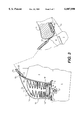
- FIG. 7 is a side view of the motorcycle having the air bag in an expanded state
- FIG. 8 is a cross-sectional view of the air bag in the expanded state.
- FIG. 9 is a cross-sectional view of a cover for a groove in a fuel tank of the motorcycle.
- a front fork 2 is supported by a front portion of a body frame 1 of a motorcycle.
- the front fork is moveable relative to the body frame 1 so as to enable steering of the motorcycle.
- a front wheel Wf is rotatably supported by the front fork 2.
- Swing arms 3 are supported by a rear portion of the body frame 1. Swing arms 3 are vertically swingably relative to the body frame 1.
- a rear wheel Wr is supported by the swing arms 3.
- a fuel tank 4 is mounted on top of a front half portion of the body frame 1.
- a seat 5 is mounted on seat rails on top of a rear half portion of the body frame 1. Due to the vertically swingable nature of the swing arms 3, the seat 5 can rise and fall relative to a roadway surface.
- the greater part of the body frame 1 is covered with a front cowl 6 and a rear cowl 7.
- a space is formed between the front portion of the fuel tank 4 and a top bridge of the front forks 2, and an air bag module M, of the air bag device embodying the invention, is disposed in the space.
- a mounting stay 10 is fixed to an upper surface of the body frame 1 in a position between the front portion of the fuel tank 4 and the top bridge of the front forks 2.
- the bag housing 12 includes a lower open portion secured onto the mounting stay 10 by a mounting piece 11.
- the bag housing 12 is formed in the shape of a cap and constructed of a lightweight material, such as a synthetic resin.
- the bag housing 12 includes a receptacle portion 12 1 and a cover portion 12 2 .
- the receptacle portion 12 1 is capable of containing an air bag 14 in a folded state.
- the cover portion covers an upper open portion of the receptacle portion 12 1 .
- the cover portion 12 2 is connected to the receptacle portion 12 1 by a hinge portion 12 3 .
- the hinge portion 12 3 is provided on one side of the cover portion 12 2 .
- the remaining sides of the cover portion 12 2 are sealed to surrounding structures by a fragile portion 12 4 .
- the fragile portion 12 4 bursts easily when an impact force larger than a predetermined value is applied to the cover portion 12 2 .
- the air bag 14 expands and the fragile portion 12 4 bursts. After the fragile portion 12 4 bursts, the cover portion 12 2 opens upwardly, with the hinge portion 12 3 acting as a fulcrum for the cover portion 12 2 . Therefore, the air bag 14 is permitted expand substantially upwards and beyond the bag housing 12.
- the air bag module M is fixed to the mounting stay 10.
- the air bag module M includes an inflator 16 which generates a gas for expanding the air bag.
- the air bag 14 is formed in the shape of a bag having an open bottom 14 1 .
- the air bag 14 is contained in the bag housing 12 in a folded state.
- a mouthpiece 15 is fixed to the open bottom 14 1 .
- the inflator 16 is fixed in an airtight manner to the mouthpiece 15.
- the inflator 16 is also directly fixed to the mounting stay 10.
- the air bag 14 is a base cloth constructed of a polyamide material, superior in tensile strength. A coating material is applied to the base cloth to prevent gas leakage. A vent hole 17 is formed in the air bag 14 at an appropriate position to controllably allow gas inside the air bag 14 to escape.
- the inflator 16 can be of any known type, such as, a gas type, a solid type, a mixing gas type, or an air suction type.
- a pair of bag anchoring members 18, 18 are constructed of a flexible material having a sufficient tensile strength to prevent separation of the air bag 14 from the body frame 1.
- the pair of bag anchoring members 18, 18 may be in the form of strings, belts, films, or sheets of material.
- the pair of bag anchoring members 18, 18 can be replaced with a single continuous bag anchoring member.
- the bag anchoring members 18, 18 are formed of a material having both flexibility and elasticity, which does not require a large space and is capable of being folded easily.
- the bag anchoring members 18, 18 may be formed by a single material or by a laminate of plural materials.
- the same material or materials used in the construction of the base cloth of the air bag 14 may also be used to construct the pair of bag anchoring members 18, 18.
- the pair of bag anchoring members 18, 18 have respective free ends connected to a middle portion of the rear side of the air bag 14.
- the bag anchoring members 18, 18 include portions inside the bag housing 12 in a folded state.
- the bag anchoring members 18, 18 also include portions exterior of the bag housing 12, each portion exiting the bag housing 12 through an outlet 19 formed in the rear wall of the bag housing 12.
- the bag anchoring members 18, 18 are directed past both the right and left sides of the fuel tank 4.
- the respective other free ends of the bag anchoring members 18, 18 are extended to below the seat 5.
- each respective other free end is secured to a mounting piece 20 which is connected to a cross member 1c of the body frame 1.
- the respective other free ends are connected to the cross member 1c by bolts or other similar connecting devices.
- the fuel tank 4 includes right and left receptacle grooves 22, 22 for receiving the bag anchoring members 18, 18.
- the right and left receptacle grooves 22, 22 extend across the overall length of the fuel tank.
- Covers 23, 23 are formed of a material having elasticity, such as a synthetic resin. Covers 23, 23, are connected to the upper open sides of receptacle grooves 22, 22 by a pressure fit engagement. When the air bag is deployed, the covers 23, 23 are contacted by the bag anchoring members 18, 18. This contact is sufficient to disengage the covers 23, 23, from the receptacle grooves 22, 22 and allow the bag anchoring members 18, 18 to exit the receptacle grooves 22, 22.
- FIG. 4 illustrates the receptacle grooves 22, 22 and covers 23, 23 near a front of the tank 4. As shown in FIG. 4, one end of each of the covers 23, 23 is extended and includes an integrally formed hinge portion 23 1 .
- the hinge portion 23 1 is pivotally connected to the outer wall of the fuel tank 4 by a hinge pin 24.
- FIG. 6 illustrates the receptacle grooves 22, 22 and covers 23, 23 near a rear of the tank 4. As shown in FIG. 6, one end of each of the covers 23, 23 is connected to the fuel tank 4 by a flexible line member 25.
- the flexible line member 25 may be in the form of a wire, string, belt, or other similar tether.
- bag anchoring members 18, 18 are received in the receptacle grooves 22, 22, as indicated by the solid line in FIGS. 4 to 6.
- the covers 23, 23 are contacted by the bag anchoring members 18, 18. This contact is sufficient to disengage the covers 23, 23 from the receptacle grooves 22, 22.
- the bag anchoring members 18, 18 exit the receptacle grooves 22, 22, as indicted by the chain lines of FIGS. 4 to 6, and extend upwardly together with the expanded air bag 14.
- a pair of right and left, guide and support pieces 26, 26 are fixed at their lower ends to the right and left sides of the body frame 1 by a bolt and nut arrangement 27. It should be understood that the guide and support pieces 26, 26 could also be fixed to the body frame 1 by alternative devices. Like the bag anchoring members 18, 18, the guide and support members 26, 26 may also be formed in the shape of a belt using a flexible material.
- the guide and support pieces 26, 26 extend into the bag housing 12 and have respective upper ends fixed to right and left outer faces of the air bag 14. Upon expansion of the air bag 14, the guide and support pieces 26, 26 extend together with the air bag and guide the air bag so that the air bag expands substantially above the body frame 1.
- a shock sensor S such as a G-force sensor is provided at the front portion of the body frame 1.
- the inflator 16 is operated and ejects a high pressure gas into the air bag 14.
- the shock sensor S detects the collision and sends a signal indicating the collision to the inflator 16.
- the inflator 16 generates a high-pressure gas.
- the gas is fed into the folded air bag 14 through the open bottom 14 1 causing the air bag to expand.
- the air bag expands approximately upwards.
- the upwards movement of the air bag 14 causes the bag anchoring members 18, 18 to be pulled upwards.
- the bag anchoring members 18, 18 open the covers 23, 23 and exit the receptacle grooves 22, 22 while extending upwards with the air bag 14.
- the flexible right and left, guide and support pieces 26, 26 also extend together with the air bag 14 and guide the upwards expansion of the air bag 14.
- the air bag 14 Since the air bag 14 is anchored to the body frame 1 under the seat 5 by the flexible bag anchoring members 18, 18, the air bag 14 is held at a position which faces the rider R, as shown in FIG. 7. This facing relationship, restrains the rider and cushions impacts directed to the rider. After deployment of the air bag 14, the high-pressure gas present in the air bag 14 is discharged slowly to the exterior through the vent hole 17.
- the bag anchoring members 18, 18, mounting the air bag 14 to the body frame 1 are flexible and elastic, the bag anchoring members 18, 18 can expand to provide addition cushioning to the rider R during an impact. Further, the flexible and elastic nature of the bag anchoring members 18, 18 diminishes the tensile force and shear force exerted on the cross member 1c when the rider R contacts the deployed air bag 14.
- FIG. 9 illustrates an alternative embodiment of the receptacle grooves 22, 22 and covers 23, 23.
- receptacle grooves 22', 22' are concave in crosssection and are formed in the right and left side faces of the fuel tank 4.
- the bag anchoring members 18, 18 are received into the receptacle grooves 22', 22'.
- Right and left covers 23', 23' close upper open sides of the right and left receptacle grooves 22', 22'.
- each cover 23' is formed of a soft material such as a synthetic resin.
- a hinge portion 23 1 is formed integrally with each cover 23'. The hinge portion 23 1 acts as a fulcrum to allow the cover 23' to open in a manner similar to the embodiment of FIG. 4.
Abstract
An air bag device for a motorcycle deploys to cushion an impact to a rider of the motorcycle during a collision. The air bag device is mounted to a body frame of the motorcycle in front of the rider. Bag anchoring members provide a connection between the air bag and the body frame. During deployment of the air bag, the bag anchoring members deploy from grooves in the motorcycle's fuel tank, and extend together with the air bag to hold the air bag securely to the frame body.
Description
1. Field of the Invention
The present invention relates to an air bag device for a motorcycle. Should a collision occur, the air bag device will cushion an impact to a rider of the motorcycle.
2. Description of Background Art
Currently, many automobiles, such as passenger cars, include an air bag device. The air bag device has been adopted as one tool for cushioning an impact to a rider should the automobile suffer a collision. Because of the impact cushioning effect exhibited by air bag devices, use of air bags in the automobile industry is wide spread.
The popularity of air bag devices in the automobile industry has created a desire among consumers for the development of an air bag device for motorcycles. Therefore, there exists a need for an air bag device, which can be used in conjunction with a motorcycle, to provide an impact cushioning effect for a rider in the event of a collision.
On a motorcycle, a rider is not surrounded by a passenger compartment, as in an automobile, but is in an open atmosphere. If the rider is to be restrained by an air bag, the volume of the air bag when expanded must be as large as possible. Also, special consideration must be given to a mounting location of the air bag. Further, a mounting assembly, connecting the air bag to the motorcycle body, must have sufficient strength.
It is an object of the present invention to provide an air bag device for a motorcycle which meets the above-mentioned criteria.
According to the present invention, there is provided an air bag device for a motorcycle, including an air bag. The air bag being capable of expanding in an upward direction. At least one flexible, bag anchoring member is connected to the air bag and connectable to a frame member of the motorcycle to attach the air bag to the frame member of the motorcycle. The at least one flexible, bag anchoring member is capable of extending in the upwards direction along with the air bag.
Also according to the present invention, there is provided a motorcycle in combination with an air bag device, the combination including an air bag. The air bag being capable of expanding in an upward direction. A frame member being a component part of the motorcycle. At least one flexible, bag anchoring member connected to the air bag and connected to the frame member of the motorcycle. The at least one flexible, bag anchoring member attaching the air bag to the frame member of the motorcycle. The at least one flexible, bag anchoring member being capable of extending in the upward direction along with the air bag.
Further scope of applicability of the present invention will become apparent from the detailed description given hereinafter. However, it should be understood that the detailed description and specific examples, while indicating preferred embodiments of the invention, are given by way of illustration only, since various changes and modifications within the spirit and scope of the invention will become apparent to those skilled in the art from this detailed description.
The present invention will become more fully understood from the detailed description given hereinbelow and the accompanying drawings which are given by way of illustration only, and thus are not limitative of the present invention, and wherein:
FIG. 1 is a side view of a motorcycle equipped with an air bag device embodying the present invention;
FIG. 2 is a plan view of the motorcycle;
FIG. 3 is a partially omitted, cross-sectional view of the portion surrounded with a chain line and indicated by arrow 3 in FIG. 1;
FIG. 4 is a cross-sectional view taken along line 4--4 in FIG. 1;
FIG. 5 is a cross-sectional view taken along line 5--5 in FIG. 1;
FIG. 6 is a cross-sectional view taken along line 6--6 in FIG. 1;
FIG. 7 is a side view of the motorcycle having the air bag in an expanded state;
FIG. 8 is a cross-sectional view of the air bag in the expanded state; and
FIG. 9 is a cross-sectional view of a cover for a groove in a fuel tank of the motorcycle.
Hereinafter, a preferred embodiment of the present invention will be described with reference to the drawings.
In FIGS. 1 and 2, a front fork 2 is supported by a front portion of a body frame 1 of a motorcycle. The front fork is moveable relative to the body frame 1 so as to enable steering of the motorcycle. A front wheel Wf is rotatably supported by the front fork 2. Swing arms 3 are supported by a rear portion of the body frame 1. Swing arms 3 are vertically swingably relative to the body frame 1. A rear wheel Wr is supported by the swing arms 3.
A fuel tank 4 is mounted on top of a front half portion of the body frame 1. A seat 5 is mounted on seat rails on top of a rear half portion of the body frame 1. Due to the vertically swingable nature of the swing arms 3, the seat 5 can rise and fall relative to a roadway surface. The greater part of the body frame 1 is covered with a front cowl 6 and a rear cowl 7.
A space is formed between the front portion of the fuel tank 4 and a top bridge of the front forks 2, and an air bag module M, of the air bag device embodying the invention, is disposed in the space.
Now, the structure of the air bag module M and a mounting structure for mounting the air bag module M to the body frame 1, will be described, mainly with reference to FIGS. 3 to 6. A mounting stay 10 is fixed to an upper surface of the body frame 1 in a position between the front portion of the fuel tank 4 and the top bridge of the front forks 2. The bag housing 12 includes a lower open portion secured onto the mounting stay 10 by a mounting piece 11. The bag housing 12 is formed in the shape of a cap and constructed of a lightweight material, such as a synthetic resin.
The bag housing 12 includes a receptacle portion 121 and a cover portion 122. The receptacle portion 121 is capable of containing an air bag 14 in a folded state. The cover portion covers an upper open portion of the receptacle portion 121. The cover portion 122 is connected to the receptacle portion 121 by a hinge portion 123. The hinge portion 123 is provided on one side of the cover portion 122. The remaining sides of the cover portion 122 are sealed to surrounding structures by a fragile portion 124. The fragile portion 124 bursts easily when an impact force larger than a predetermined value is applied to the cover portion 122.
As shown in FIG. 8, when an impact force larger than the predetermined value acts on the motorcycle, the air bag 14 expands and the fragile portion 124 bursts. After the fragile portion 124 bursts, the cover portion 122 opens upwardly, with the hinge portion 123 acting as a fulcrum for the cover portion 122. Therefore, the air bag 14 is permitted expand substantially upwards and beyond the bag housing 12.
The air bag module M is fixed to the mounting stay 10. The air bag module M includes an inflator 16 which generates a gas for expanding the air bag. The air bag 14 is formed in the shape of a bag having an open bottom 141. The air bag 14 is contained in the bag housing 12 in a folded state. A mouthpiece 15 is fixed to the open bottom 141. The inflator 16 is fixed in an airtight manner to the mouthpiece 15. The inflator 16 is also directly fixed to the mounting stay 10.
The air bag 14 is a base cloth constructed of a polyamide material, superior in tensile strength. A coating material is applied to the base cloth to prevent gas leakage. A vent hole 17 is formed in the air bag 14 at an appropriate position to controllably allow gas inside the air bag 14 to escape. The inflator 16 can be of any known type, such as, a gas type, a solid type, a mixing gas type, or an air suction type.
A pair of bag anchoring members 18, 18 are constructed of a flexible material having a sufficient tensile strength to prevent separation of the air bag 14 from the body frame 1. The pair of bag anchoring members 18, 18 may be in the form of strings, belts, films, or sheets of material. As an alternative, the pair of bag anchoring members 18, 18 can be replaced with a single continuous bag anchoring member.
Preferably, the bag anchoring members 18, 18 are formed of a material having both flexibility and elasticity, which does not require a large space and is capable of being folded easily. The bag anchoring members 18, 18 may be formed by a single material or by a laminate of plural materials. For example, the same material or materials used in the construction of the base cloth of the air bag 14 may also be used to construct the pair of bag anchoring members 18, 18.
As shown in FIG. 3, the pair of bag anchoring members 18, 18 have respective free ends connected to a middle portion of the rear side of the air bag 14. The bag anchoring members 18, 18 include portions inside the bag housing 12 in a folded state. The bag anchoring members 18, 18 also include portions exterior of the bag housing 12, each portion exiting the bag housing 12 through an outlet 19 formed in the rear wall of the bag housing 12. The bag anchoring members 18, 18 are directed past both the right and left sides of the fuel tank 4. Then, the respective other free ends of the bag anchoring members 18, 18 are extended to below the seat 5. At a position just under the front portion of the seat 5, each respective other free end is secured to a mounting piece 20 which is connected to a cross member 1c of the body frame 1. The respective other free ends are connected to the cross member 1c by bolts or other similar connecting devices. By the above attachment of the bag anchoring members 18, 18, the mounting between the air bag device and the body frame 1 is strong and neat in appearance.
The fuel tank 4 includes right and left receptacle grooves 22, 22 for receiving the bag anchoring members 18, 18. The right and left receptacle grooves 22, 22 extend across the overall length of the fuel tank.
As shown in FIG. 5, the receptacle grooves 22, 22, in a middle of the tank 4, each have a V-shaped cross-section and their upper open sides are covered with covers 23, 23. Covers 23, 23 are formed of a material having elasticity, such as a synthetic resin. Covers 23, 23, are connected to the upper open sides of receptacle grooves 22, 22 by a pressure fit engagement. When the air bag is deployed, the covers 23, 23 are contacted by the bag anchoring members 18, 18. This contact is sufficient to disengage the covers 23, 23, from the receptacle grooves 22, 22 and allow the bag anchoring members 18, 18 to exit the receptacle grooves 22, 22.
FIG. 4 illustrates the receptacle grooves 22, 22 and covers 23, 23 near a front of the tank 4. As shown in FIG. 4, one end of each of the covers 23, 23 is extended and includes an integrally formed hinge portion 231. The hinge portion 231 is pivotally connected to the outer wall of the fuel tank 4 by a hinge pin 24.
FIG. 6 illustrates the receptacle grooves 22, 22 and covers 23, 23 near a rear of the tank 4. As shown in FIG. 6, one end of each of the covers 23, 23 is connected to the fuel tank 4 by a flexible line member 25. The flexible line member 25 may be in the form of a wire, string, belt, or other similar tether.
Normally, bag anchoring members 18, 18 are received in the receptacle grooves 22, 22, as indicated by the solid line in FIGS. 4 to 6. When the air bag is deployed, the covers 23, 23 are contacted by the bag anchoring members 18, 18. This contact is sufficient to disengage the covers 23, 23 from the receptacle grooves 22, 22. At this point, the bag anchoring members 18, 18 exit the receptacle grooves 22, 22, as indicted by the chain lines of FIGS. 4 to 6, and extend upwardly together with the expanded air bag 14.
As shown in FIG. 3, a pair of right and left, guide and support pieces 26, 26 are fixed at their lower ends to the right and left sides of the body frame 1 by a bolt and nut arrangement 27. It should be understood that the guide and support pieces 26, 26 could also be fixed to the body frame 1 by alternative devices. Like the bag anchoring members 18, 18, the guide and support members 26, 26 may also be formed in the shape of a belt using a flexible material. The guide and support pieces 26, 26 extend into the bag housing 12 and have respective upper ends fixed to right and left outer faces of the air bag 14. Upon expansion of the air bag 14, the guide and support pieces 26, 26 extend together with the air bag and guide the air bag so that the air bag expands substantially above the body frame 1.
As shown in FIG. 1, a shock sensor S such as a G-force sensor is provided at the front portion of the body frame 1. In response to a signal provided from the shock sensor S, the inflator 16 is operated and ejects a high pressure gas into the air bag 14.
The operation of the air bag device, according to the invention, will now be described. Should the motorcycle strike against an obstacle, the shock sensor S detects the collision and sends a signal indicating the collision to the inflator 16. The inflator 16 generates a high-pressure gas. The gas is fed into the folded air bag 14 through the open bottom 141 causing the air bag to expand.
As shown in FIGS. 7 and 8, the air bag expands approximately upwards. The upwards movement of the air bag 14 causes the bag anchoring members 18, 18 to be pulled upwards. The bag anchoring members 18, 18 open the covers 23, 23 and exit the receptacle grooves 22, 22 while extending upwards with the air bag 14. The flexible right and left, guide and support pieces 26, 26 also extend together with the air bag 14 and guide the upwards expansion of the air bag 14.
Since the air bag 14 is anchored to the body frame 1 under the seat 5 by the flexible bag anchoring members 18, 18, the air bag 14 is held at a position which faces the rider R, as shown in FIG. 7. This facing relationship, restrains the rider and cushions impacts directed to the rider. After deployment of the air bag 14, the high-pressure gas present in the air bag 14 is discharged slowly to the exterior through the vent hole 17.
Since the bag anchoring members 18, 18, mounting the air bag 14 to the body frame 1, are flexible and elastic, the bag anchoring members 18, 18 can expand to provide addition cushioning to the rider R during an impact. Further, the flexible and elastic nature of the bag anchoring members 18, 18 diminishes the tensile force and shear force exerted on the cross member 1c when the rider R contacts the deployed air bag 14.
FIG. 9 illustrates an alternative embodiment of the receptacle grooves 22, 22 and covers 23, 23. As shown in FIG. 9, receptacle grooves 22', 22' are concave in crosssection and are formed in the right and left side faces of the fuel tank 4. The bag anchoring members 18, 18 are received into the receptacle grooves 22', 22'. Right and left covers 23', 23' close upper open sides of the right and left receptacle grooves 22', 22'.
By contrast to the previous embodiment, the covers 23', 23' are fixed to the bottoms of the grooves 22', 22' by a plurality of fixing means 28. Each cover 23' is formed of a soft material such as a synthetic resin. A hinge portion 231 is formed integrally with each cover 23'. The hinge portion 231 acts as a fulcrum to allow the cover 23' to open in a manner similar to the embodiment of FIG. 4.
The invention being thus described, it will be obvious that the same may be varied in many ways. Such variations are not to be regarded as a departure from the spirit and scope of the invention, and all such modifications as would be obvious to one skilled in the art are intended to be included within the scope of the following claims.
Claims (17)
1. A motorcycle in combination with an air bag device comprising:
an air bag, said air bag being capable of expanding in an upward direction;
a frame member of said motorcycle; and
right and left flexible, bag anchoring members connected to said air bag and connected to said frame member of said motorcycle, said right and left flexible, bag anchoring members attaching said air bag to said frame member of said motorcycle, and said right and left flexible, bag anchoring members being capable of extending in the upward direction along with said air bag.
2. The motorcycle in combination with an air bag defined in claim 1, wherein said frame member of said motorcycle is located below a seat of said motorcycle.
3. The motorcycle in combination with an air bag defined in claim 1, wherein said frame member of said motorcycle is a cross member.
4. The motorcycle in combination with an air bag defined in claim 1, wherein said right and left flexible, bag anchoring members extend in an extension direction away from said air bag, the extension direction being opposite to a forward direction of travel of said motorcycle.
5. The motorcycle in combination with an air bag defined in claim 1, further comprising:
a right groove and a left groove in a fuel tank of said motorcycle, said right groove and said left groove receiving a portion of said right and left flexible, bag anchoring members intermediate the connections between said right and left flexible, bag anchoring members and said air bag and the connections between said right and left flexible, bag anchoring members and said frame member, respectively.
6. The motorcycle in combination with an air bag defined in claim 5, further comprising:
a right cover and a left cover for covering said portions of said right and left flexible, bag anchoring members while said portions of said right and left flexible, bag anchoring members are received in said right and left grooves in said fuel tank of said motorcycle, respectively.
7. The motorcycle in combination with an air bag defined in claim 1, wherein said right and left flexible, bag anchoring members are made in the form of belts and constructed of an elastic material.
8. A motorcycle in combination with an air bag device comprising:
an air bag, said air bag being capable of expanding in an upward direction;
a frame member of said motorcycle; and
at least one guide and support piece, said at least one guide and support piece being connected to right and left side faces of said air bag and being connected to said frame member of said motorcycle.
9. The motorcycle in combination with an air bag defined in claim 8, wherein said frame member of said motorcycle is located below a seat of said motorcycle.
10. The motorcycle in combination with an air bag defined in claim 8, wherein said frame member of said motorcycle is a cross member.
11. The motorcycle in combination with an air bag defined in claim 8, wherein said at least one guide and support piece is made in the form of a belt and constructed of an elastic material.
12. The motorcycle in combination with an air bag defined in claim 8, wherein said at least one guide and support piece includes right and left flexible, bag anchoring members.
13. A motorcycle in combination with an air bag device comprising:
an air bag, said air bag being capable of expanding in an upward direction;
a frame member of said motorcycle;
at least one flexible, bag anchoring member connected to said air bag and connected to said frame member of said motorcycle, said at least one flexible, bag anchoring member attaching said air bag to said frame member of said motorcycle, and said at least one flexible, bag anchoring member being capable of extending in the upward direction along with said air bag; and
at least one groove in a fuel tank of said motorcycle, said at least one groove receiving a portion of said at least one flexible, bag anchoring member intermediate the connection between said at least one flexible, bag anchoring member and said air bag and the connection between said at least one flexible, bag anchoring member and said frame member.
14. The motorcycle in combination with an air bag defined in claim 13, wherein said frame member of said motorcycle is located below a seat of said motorcycle.
15. The motorcycle in combination with an air bag defined in claim 13, wherein said frame member of said motorcycle is a cross member.
16. The motorcycle in combination with an air bag defined in claim 13, further comprising:
a cover for covering said portion of said at least one flexible, bag anchoring member while said portion of said at least one flexible, bag anchoring member is received in said at least one groove in said fuel tank of said motorcycle.
17. The motorcycle in combination with an air bag defined in claim 13, wherein said at least one flexible, bag anchoring member is made in the form of a belt and constructed of an elastic material.
Applications Claiming Priority (2)
| Application Number | Priority Date | Filing Date | Title |
|---|---|---|---|
| JP19591996A JP3592447B2 (en) | 1996-07-25 | 1996-07-25 | Airbag device for motorcycles |
| JP8-195919 | 1996-07-25 |
Publications (1)
| Publication Number | Publication Date |
|---|---|
| US6007090A true US6007090A (en) | 1999-12-28 |
Family
ID=16349172
Family Applications (1)
| Application Number | Title | Priority Date | Filing Date |
|---|---|---|---|
| US08/900,841 Expired - Lifetime US6007090A (en) | 1996-07-25 | 1997-07-25 | Air bag device for a motorcycle |
Country Status (4)
| Country | Link |
|---|---|
| US (1) | US6007090A (en) |
| JP (1) | JP3592447B2 (en) |
| DE (1) | DE19729627B4 (en) |
| IT (1) | IT1293857B1 (en) |
Cited By (38)
| Publication number | Priority date | Publication date | Assignee | Title |
|---|---|---|---|---|
| US6386576B1 (en) * | 1997-11-04 | 2002-05-14 | Deka Products Limited Partnership | Cushion system for mobile subject |
| EP1234731A1 (en) * | 2001-02-21 | 2002-08-28 | Bayerische Motoren Werke Aktiengesellschaft | Airbagunit |
| US20020130496A1 (en) * | 2001-03-08 | 2002-09-19 | Takeyasu Itabashi | Vehicle air bag structure |
| US20030132616A1 (en) * | 2001-10-02 | 2003-07-17 | Yoshitaka Yanagibashi | Airbag system |
| US20030137137A1 (en) * | 2001-10-02 | 2003-07-24 | Yoshitaka Yanagibashi | Airbag system |
| EP1338479A1 (en) * | 2002-02-20 | 2003-08-27 | Honda Giken Kogyo Kabushiki Kaisha | Airbag apparatus for a compact vehicle |
| US20030214122A1 (en) * | 2002-05-15 | 2003-11-20 | Takata Corporation | Air bag apparatus for motorcycle, method of manufacturing air bag apparatus for motorcycle, and motorcycle with air bag apparatus |
| US20030214121A1 (en) * | 2002-05-15 | 2003-11-20 | Takata Corporation | Air bag apparatus for motorcycle, method of manufacturing air bag apparatus for motorcycle, and motorcycle with air bag apparatus |
| US20030218317A1 (en) * | 2002-03-27 | 2003-11-27 | Takeshi Yamazaki | Airbag apparatus |
| US20030222438A1 (en) * | 2002-03-06 | 2003-12-04 | Toshiya Nagatsuyu | Airbag apparatus for motorcycles |
| US20040026904A1 (en) * | 2002-04-18 | 2004-02-12 | Takeshi Yamazaki | Air bag system in scooter type vehicle |
| US20040051281A1 (en) * | 2002-06-27 | 2004-03-18 | Takata Corporation | Airbag apparatus, motorcycle with airbag apparatus, and method of manufacturing airbag apparatus |
| US20040207189A1 (en) * | 2003-04-16 | 2004-10-21 | Takata Corporation | Airbag device and motorcycle with the airbag device |
| US20050040628A1 (en) * | 2003-08-22 | 2005-02-24 | Takata Corporation | Airbag apparatus, motorbike with airbag apparatus |
| US20070040351A1 (en) * | 2005-06-24 | 2007-02-22 | Bozung Dennis A | Motorcycle anti-tipover device |
| US20070052218A1 (en) * | 2005-09-07 | 2007-03-08 | Takata Corporation | Airbag Apparatus And Motorcycle Having The Same |
| US20070052213A1 (en) * | 2005-09-07 | 2007-03-08 | Takata Corporation | Airbag Apparatus And Motorcycle With Airbag Apparatus |
| US20070052214A1 (en) * | 2005-09-07 | 2007-03-08 | Takata Corporation | Airbag Apparatus And Motorcycle Having The Same |
| US20070052217A1 (en) * | 2005-09-07 | 2007-03-08 | Takata Corporation | Airbag Apparatus And Motorcycle Having The Same |
| EP1762478A1 (en) * | 2005-09-08 | 2007-03-14 | Honda Motor Co., Ltd | Air bag support belt storing structure |
| EP1762440A1 (en) * | 2005-09-08 | 2007-03-14 | HONDA MOTOR CO., Ltd. | Air bag module cover structure |
| US20070057489A1 (en) * | 2005-09-07 | 2007-03-15 | Honda Motor Co., Ltd. | Air bag module mounting structure |
| US20070057488A1 (en) * | 2005-08-09 | 2007-03-15 | Honda Motor Co., Ltd. | Air bag module cover structure |
| US20070063491A1 (en) * | 2005-09-09 | 2007-03-22 | Honda Motor Co., Ltd. | Air bag support belt storing structure |
| US20070069506A1 (en) * | 2005-09-26 | 2007-03-29 | Takata Corporation | Airbag Apparatus And Motorcycle Having The Same |
| US20070085307A1 (en) * | 2005-10-18 | 2007-04-19 | Honda Motor Co. Ltd. | Air bag support belt cover structure |
| US20070085306A1 (en) * | 2005-10-17 | 2007-04-19 | Takata Corporation | Airbag apparatus and motorcycle provided with airbag apparatus |
| US20070170702A1 (en) * | 2006-01-25 | 2007-07-26 | Yasuhito Miyata | Airbag System and Motorcycle with Airbag System |
| US20070170703A1 (en) * | 2006-01-25 | 2007-07-26 | Yasuhito Miyata | Airbag System and Motorcycle with Airbag System |
| US20070170704A1 (en) * | 2006-01-25 | 2007-07-26 | Yasuhito Miyata | Motorcycle Airbag System and Motorcyle |
| US20080053728A1 (en) * | 2004-04-26 | 2008-03-06 | Suzuki Kabushiki Kaisha | Snowmobile with airbag system |
| US20080079242A1 (en) * | 2006-09-29 | 2008-04-03 | Honda Motor Co., Ltd. | Airbag system for motorcycle |
| US7357407B2 (en) * | 2003-05-19 | 2008-04-15 | Honda Motor Co., Ltd. | Air bag system |
| US20090167001A1 (en) * | 2007-12-27 | 2009-07-02 | Kazuhiro Suzuki | Low-floor type vehicle |
| US20090194980A1 (en) * | 2008-01-31 | 2009-08-06 | Yuki Kobayashi | Airbag device |
| US20090250910A1 (en) * | 2008-04-02 | 2009-10-08 | Kei Tsujimoto | Airbag device and motorcycle with airbag device |
| JP2016507425A (en) * | 2013-02-21 | 2016-03-10 | フェニュベシュ アンドラス | Collision protection system |
| US11407378B2 (en) | 2019-03-18 | 2022-08-09 | Andras Fenyves | Airbag system and related methods of inflating an airbag |
Families Citing this family (24)
| Publication number | Priority date | Publication date | Assignee | Title |
|---|---|---|---|---|
| JP2002137780A (en) * | 2000-11-02 | 2002-05-14 | Yamaha Motor Co Ltd | Airbag device for motorcycle |
| JP4633910B2 (en) * | 2000-11-02 | 2011-02-16 | ヤマハ発動機株式会社 | Airbag device for motorcycle |
| DE20021180U1 (en) * | 2000-12-14 | 2002-04-18 | Pumpe Ulrich | Motorcyclist protection device |
| DE10105459A1 (en) * | 2001-02-07 | 2002-08-08 | Bayerische Motoren Werke Ag | Upper-body restraint for use on motorcycles for accident safety, has gasbag to be inflated by a generator and fitted on a motorcycle bodywork part like a fuel tank in front of the rider |
| DE10120848A1 (en) | 2001-04-27 | 2002-10-31 | Bayerische Motoren Werke Ag | Vehicle (G) |
| DE10120851A1 (en) * | 2001-04-27 | 2002-10-31 | Bayerische Motoren Werke Ag | Motorcycle with passenger restraint system and automatic braking of front wheel in frontal impact crash situation |
| DE10120852A1 (en) * | 2001-04-27 | 2002-10-31 | Bayerische Motoren Werke Ag | Motorcycle with airbag passenger restraint system and automatic adjustment of wheel suspension characteristics in frontal impact crash situation |
| DE10120849A1 (en) * | 2001-04-27 | 2002-10-31 | Bayerische Motoren Werke Ag | Motorcycle with passenger restraint system providing automatic lowering of seat height in crash situation |
| JP4310115B2 (en) | 2002-03-06 | 2009-08-05 | 本田技研工業株式会社 | Scooter type motorcycle with airbag device |
| JP4226259B2 (en) * | 2002-04-05 | 2009-02-18 | 本田技研工業株式会社 | Airbag device for small vehicles |
| JP4119155B2 (en) * | 2002-04-22 | 2008-07-16 | 本田技研工業株式会社 | Airbag device for small vehicle |
| DE10247120A1 (en) * | 2002-10-09 | 2004-06-17 | Bayerische Motoren Werke Ag | Restraining system for two or three wheeled vehicles such as motorcycles for driver safety in the form of airbags in the tank region |
| JP4525484B2 (en) * | 2005-06-23 | 2010-08-18 | 豊田合成株式会社 | Airbag device for motorcycle |
| JP4822777B2 (en) * | 2005-09-07 | 2011-11-24 | タカタ株式会社 | Airbag device, motorcycle with airbag device |
| JP4766564B2 (en) * | 2006-09-29 | 2011-09-07 | 本田技研工業株式会社 | Motorcycle airbag device |
| JP4878991B2 (en) * | 2006-11-16 | 2012-02-15 | 本田技研工業株式会社 | On-board antenna installation structure for motorcycles |
| DE102007050885A1 (en) * | 2007-07-04 | 2009-01-15 | Takata-Petri Ag | Airbag for use in motorcycle, has indent facing rider or facing away from rider in inflated state and running horizontally between upper and lower airbag regions, which are connected with each other by retaining unit |
| JP5222219B2 (en) * | 2009-04-28 | 2013-06-26 | 本田技研工業株式会社 | Saddle riding vehicle |
| JP2011000962A (en) * | 2009-06-18 | 2011-01-06 | Honda Motor Co Ltd | Airbag device of saddle-riding type vehicle |
| JP5478480B2 (en) * | 2010-12-17 | 2014-04-23 | 本田技研工業株式会社 | Airbag device for saddle riding type vehicle |
| DE102013216711A1 (en) | 2013-08-22 | 2015-02-26 | Robert Bosch Gmbh | A method of activating a personal protection device for a motorcycle and personal protection system |
| JP6208514B2 (en) * | 2013-09-30 | 2017-10-04 | 本田技研工業株式会社 | Saddle riding |
| JP2016049959A (en) * | 2014-08-29 | 2016-04-11 | 隆博 笹川 | Motor cycle with air bag |
| JP6759935B2 (en) * | 2016-09-28 | 2020-09-23 | 豊田合成株式会社 | Airbag device for motorcycles |
Citations (9)
| Publication number | Priority date | Publication date | Assignee | Title |
|---|---|---|---|---|
| US3930667A (en) * | 1975-02-14 | 1976-01-06 | Osuchowski Andrew J | Inflatable garment for crash protection |
| US4227717A (en) * | 1979-04-04 | 1980-10-14 | Bouvier Julien J | Motorcycle safety device |
| DE8508646U1 (en) * | 1985-03-22 | 1985-06-27 | Sporner, Alexander, Dr.-Ing., 8000 München | Fall arrest and deflection device for occupants of motorized two-wheeled vehicles |
| DE9114743U1 (en) * | 1991-11-27 | 1992-02-20 | Heidtmann, Helmut, 7500 Karlsruhe, De | |
| DE9310544U1 (en) * | 1993-07-15 | 1993-09-02 | Elkamet Kunststofftechnik Gmbh | Security system on a motorcycle |
| US5362101A (en) * | 1991-03-12 | 1994-11-08 | Toyota Jidosha Kabushiki Kaisha | Air bag device |
| DE19519297A1 (en) * | 1994-06-03 | 1995-12-07 | Volkswagen Ag | Side airbag for vehicle |
| US5609363A (en) * | 1995-11-17 | 1997-03-11 | Chrysler Corporation | Passenger side air bag with tether |
| US5636862A (en) * | 1995-09-07 | 1997-06-10 | General Motors Corporation | Air bag assembly with tether |
-
1996
- 1996-07-25 JP JP19591996A patent/JP3592447B2/en not_active Expired - Fee Related
-
1997
- 1997-06-30 IT IT97TO000568A patent/IT1293857B1/en active IP Right Grant
- 1997-07-10 DE DE19729627A patent/DE19729627B4/en not_active Expired - Fee Related
- 1997-07-25 US US08/900,841 patent/US6007090A/en not_active Expired - Lifetime
Patent Citations (9)
| Publication number | Priority date | Publication date | Assignee | Title |
|---|---|---|---|---|
| US3930667A (en) * | 1975-02-14 | 1976-01-06 | Osuchowski Andrew J | Inflatable garment for crash protection |
| US4227717A (en) * | 1979-04-04 | 1980-10-14 | Bouvier Julien J | Motorcycle safety device |
| DE8508646U1 (en) * | 1985-03-22 | 1985-06-27 | Sporner, Alexander, Dr.-Ing., 8000 München | Fall arrest and deflection device for occupants of motorized two-wheeled vehicles |
| US5362101A (en) * | 1991-03-12 | 1994-11-08 | Toyota Jidosha Kabushiki Kaisha | Air bag device |
| DE9114743U1 (en) * | 1991-11-27 | 1992-02-20 | Heidtmann, Helmut, 7500 Karlsruhe, De | |
| DE9310544U1 (en) * | 1993-07-15 | 1993-09-02 | Elkamet Kunststofftechnik Gmbh | Security system on a motorcycle |
| DE19519297A1 (en) * | 1994-06-03 | 1995-12-07 | Volkswagen Ag | Side airbag for vehicle |
| US5636862A (en) * | 1995-09-07 | 1997-06-10 | General Motors Corporation | Air bag assembly with tether |
| US5609363A (en) * | 1995-11-17 | 1997-03-11 | Chrysler Corporation | Passenger side air bag with tether |
Cited By (84)
| Publication number | Priority date | Publication date | Assignee | Title |
|---|---|---|---|---|
| US6386576B1 (en) * | 1997-11-04 | 2002-05-14 | Deka Products Limited Partnership | Cushion system for mobile subject |
| EP1234731A1 (en) * | 2001-02-21 | 2002-08-28 | Bayerische Motoren Werke Aktiengesellschaft | Airbagunit |
| US20020130496A1 (en) * | 2001-03-08 | 2002-09-19 | Takeyasu Itabashi | Vehicle air bag structure |
| US6773028B2 (en) * | 2001-03-08 | 2004-08-10 | Honda Giken Kogyo Kabushiki Kaisha | Vehicle air bag structure |
| US20030132616A1 (en) * | 2001-10-02 | 2003-07-17 | Yoshitaka Yanagibashi | Airbag system |
| US20030137137A1 (en) * | 2001-10-02 | 2003-07-24 | Yoshitaka Yanagibashi | Airbag system |
| US6991254B2 (en) * | 2001-10-02 | 2006-01-31 | Honda Giken Kogyo Kabushiki Kaisha | Airbag system |
| US6854762B2 (en) * | 2001-10-02 | 2005-02-15 | Honda Giken Kogyo Kabushiki Kaisha | Airbag system |
| EP1338479A1 (en) * | 2002-02-20 | 2003-08-27 | Honda Giken Kogyo Kabushiki Kaisha | Airbag apparatus for a compact vehicle |
| US20040017066A1 (en) * | 2002-02-20 | 2004-01-29 | Takeshi Kuroe | Airbag apparatus for a compact vehicle |
| US6846009B2 (en) | 2002-02-20 | 2005-01-25 | Honda Giken Kogyo Kabushiki Kaisha | Airbag apparatus for a compact vehicle |
| US20030222438A1 (en) * | 2002-03-06 | 2003-12-04 | Toshiya Nagatsuyu | Airbag apparatus for motorcycles |
| US6848709B2 (en) * | 2002-03-06 | 2005-02-01 | Da Giken Kogyo Kabushiki Kaisha | Airbag apparatus for motorcycles |
| US20030218317A1 (en) * | 2002-03-27 | 2003-11-27 | Takeshi Yamazaki | Airbag apparatus |
| US7029029B2 (en) * | 2002-03-27 | 2006-04-18 | Honda Giken Kogyo Kabushiki Kaisha | Airbag apparatus |
| US20040026904A1 (en) * | 2002-04-18 | 2004-02-12 | Takeshi Yamazaki | Air bag system in scooter type vehicle |
| US6932379B2 (en) * | 2002-04-18 | 2005-08-23 | Honda Giken Kogyo Kabushiki Kaisha | Air bag system in scooter type vehicle |
| US20030214122A1 (en) * | 2002-05-15 | 2003-11-20 | Takata Corporation | Air bag apparatus for motorcycle, method of manufacturing air bag apparatus for motorcycle, and motorcycle with air bag apparatus |
| US20030214121A1 (en) * | 2002-05-15 | 2003-11-20 | Takata Corporation | Air bag apparatus for motorcycle, method of manufacturing air bag apparatus for motorcycle, and motorcycle with air bag apparatus |
| US7044499B2 (en) * | 2002-05-15 | 2006-05-16 | Takata Corporation | Air bag apparatus for motorcycle, method of manufacturing air bag apparatus for motorcycle, and motorcycle with air bag apparatus |
| US7404570B2 (en) | 2002-05-15 | 2008-07-29 | Takata Corporation | Air bag apparatus for motorcycle, method of manufacturing air bag apparatus for motorcycle, and motorcycle with air bag apparatus |
| US20040051281A1 (en) * | 2002-06-27 | 2004-03-18 | Takata Corporation | Airbag apparatus, motorcycle with airbag apparatus, and method of manufacturing airbag apparatus |
| US7331600B2 (en) * | 2002-06-27 | 2008-02-19 | Takata Corporation | Airbag apparatus, motorcycle with airbag apparatus, and method of manufacturing airbag apparatus |
| US7568731B2 (en) * | 2003-04-16 | 2009-08-04 | Takata Corporation | Airbag device and motorcycle with the airbag device |
| US7275762B2 (en) * | 2003-04-16 | 2007-10-02 | Takata Corporation | Airbag device and motorcycle with the airbag device |
| US20040207189A1 (en) * | 2003-04-16 | 2004-10-21 | Takata Corporation | Airbag device and motorcycle with the airbag device |
| US7357407B2 (en) * | 2003-05-19 | 2008-04-15 | Honda Motor Co., Ltd. | Air bag system |
| US7134684B2 (en) | 2003-08-22 | 2006-11-14 | Takata Corporation | Airbag apparatus, motorbike with airbag apparatus |
| US20050040628A1 (en) * | 2003-08-22 | 2005-02-24 | Takata Corporation | Airbag apparatus, motorbike with airbag apparatus |
| US7661500B2 (en) * | 2004-04-26 | 2010-02-16 | Suzuki Kabushiki Kaisha | Snowmobile with airbag system |
| US20080053728A1 (en) * | 2004-04-26 | 2008-03-06 | Suzuki Kabushiki Kaisha | Snowmobile with airbag system |
| US7549664B2 (en) | 2005-06-24 | 2009-06-23 | M.C. Technologies Group, Inc. | Motorcycle anti-tipover device |
| US20070040351A1 (en) * | 2005-06-24 | 2007-02-22 | Bozung Dennis A | Motorcycle anti-tipover device |
| US20070057488A1 (en) * | 2005-08-09 | 2007-03-15 | Honda Motor Co., Ltd. | Air bag module cover structure |
| US7293793B2 (en) | 2005-09-07 | 2007-11-13 | Takata Corporation | Airbag apparatus and motorcycle having the same |
| US7837222B2 (en) | 2005-09-07 | 2010-11-23 | Takata Corporation | Airbag apparatus and motorcycle having the same |
| CN1927641B (en) * | 2005-09-07 | 2012-04-25 | 高田株式会社 | Airbag apparatus and motorcycle having the same |
| CN1927642B (en) * | 2005-09-07 | 2012-01-25 | 高田株式会社 | Airbag apparatus and motorcycle having same |
| US7780189B2 (en) | 2005-09-07 | 2010-08-24 | Takata Corporation | Airbag apparatus and motorcycle having the same |
| US20070052218A1 (en) * | 2005-09-07 | 2007-03-08 | Takata Corporation | Airbag Apparatus And Motorcycle Having The Same |
| US20070052213A1 (en) * | 2005-09-07 | 2007-03-08 | Takata Corporation | Airbag Apparatus And Motorcycle With Airbag Apparatus |
| US7562900B2 (en) * | 2005-09-07 | 2009-07-21 | Takata Corporation | Airbag apparatus and motorcycle with airbag apparatus |
| US7556283B2 (en) * | 2005-09-07 | 2009-07-07 | Honda Motor Co., Ltd. | Air bag module mounting structure |
| US20070052214A1 (en) * | 2005-09-07 | 2007-03-08 | Takata Corporation | Airbag Apparatus And Motorcycle Having The Same |
| US20070052217A1 (en) * | 2005-09-07 | 2007-03-08 | Takata Corporation | Airbag Apparatus And Motorcycle Having The Same |
| US20070057489A1 (en) * | 2005-09-07 | 2007-03-15 | Honda Motor Co., Ltd. | Air bag module mounting structure |
| KR100861974B1 (en) * | 2005-09-08 | 2008-10-07 | 혼다 기켄 고교 가부시키가이샤 | Air-bag module cover structure |
| CN100462259C (en) * | 2005-09-08 | 2009-02-18 | 本田技研工业株式会社 | Air bag module cover structure |
| AU2006203451B2 (en) * | 2005-09-08 | 2011-12-08 | Honda Motor Co., Ltd. | Air bag module cover structure |
| EP1762478A1 (en) * | 2005-09-08 | 2007-03-14 | Honda Motor Co., Ltd | Air bag support belt storing structure |
| KR100808530B1 (en) | 2005-09-08 | 2008-02-29 | 혼다 기켄 고교 가부시키가이샤 | Receiving structure for air bag supporting belt |
| US7789416B2 (en) * | 2005-09-08 | 2010-09-07 | Honda Motor Co., Ltd. | Air bag module cover structure |
| EP1762440A1 (en) * | 2005-09-08 | 2007-03-14 | HONDA MOTOR CO., Ltd. | Air bag module cover structure |
| AU2006204664B2 (en) * | 2005-09-08 | 2012-01-19 | Honda Motor Co., Ltd. | Air bag support belt storing structure |
| CN100441445C (en) * | 2005-09-08 | 2008-12-10 | 本田技研工业株式会社 | Air bag support belt storing structure |
| US20070063491A1 (en) * | 2005-09-09 | 2007-03-22 | Honda Motor Co., Ltd. | Air bag support belt storing structure |
| US7578516B2 (en) * | 2005-09-09 | 2009-08-25 | Honda Motor Co., Ltd. | Air bag support belt storing structure |
| US7547039B2 (en) | 2005-09-26 | 2009-06-16 | Takata Corporation | Airbag apparatus and motorcycle having the same |
| US20070069506A1 (en) * | 2005-09-26 | 2007-03-29 | Takata Corporation | Airbag Apparatus And Motorcycle Having The Same |
| CN1939797B (en) * | 2005-09-26 | 2012-01-25 | 高田株式会社 | Airbag apparatus and motorcycle having the same |
| US7429059B2 (en) * | 2005-10-17 | 2008-09-30 | Takata Corporation | Airbag apparatus and motorcycle provided with airbag apparatus |
| US20070085306A1 (en) * | 2005-10-17 | 2007-04-19 | Takata Corporation | Airbag apparatus and motorcycle provided with airbag apparatus |
| EP1777120A1 (en) * | 2005-10-18 | 2007-04-25 | HONDA MOTOR CO., Ltd. | Air bag support belt cover structure |
| US7255363B2 (en) | 2005-10-18 | 2007-08-14 | Honda Motor Co., Ltd. | Air bag support belt cover structure |
| AU2006220402B8 (en) * | 2005-10-18 | 2012-03-22 | Honda Motor Co., Ltd. | Motorcycle with air bag support belt cover structure |
| KR100795642B1 (en) | 2005-10-18 | 2008-01-17 | 혼다 기켄 고교 가부시키가이샤 | Air bag supporting belt cover structure |
| AU2006220402B2 (en) * | 2005-10-18 | 2011-11-10 | Honda Motor Co., Ltd. | Motorcycle with air bag support belt cover structure |
| US20070085307A1 (en) * | 2005-10-18 | 2007-04-19 | Honda Motor Co. Ltd. | Air bag support belt cover structure |
| US7588264B2 (en) | 2006-01-25 | 2009-09-15 | Takata Corporation | Airbag system and motorcycle with airbag system |
| US7566070B2 (en) | 2006-01-25 | 2009-07-28 | Takata Corporation | Airbag system and motorcycle with airbag system |
| US7686328B2 (en) | 2006-01-25 | 2010-03-30 | Takata Corporation | Motorcycle airbag system and motorcycle |
| US20070170702A1 (en) * | 2006-01-25 | 2007-07-26 | Yasuhito Miyata | Airbag System and Motorcycle with Airbag System |
| US20070170703A1 (en) * | 2006-01-25 | 2007-07-26 | Yasuhito Miyata | Airbag System and Motorcycle with Airbag System |
| US20070170704A1 (en) * | 2006-01-25 | 2007-07-26 | Yasuhito Miyata | Motorcycle Airbag System and Motorcyle |
| US7823921B2 (en) * | 2006-09-29 | 2010-11-02 | Honda Motor Co., Ltd. | Airbag system for motorcycle |
| US20080079242A1 (en) * | 2006-09-29 | 2008-04-03 | Honda Motor Co., Ltd. | Airbag system for motorcycle |
| US8002305B2 (en) * | 2007-12-27 | 2011-08-23 | Honda Motor Co., Ltd. | Low-floor type vehicle |
| US20090167001A1 (en) * | 2007-12-27 | 2009-07-02 | Kazuhiro Suzuki | Low-floor type vehicle |
| US7900955B2 (en) * | 2008-01-31 | 2011-03-08 | Honda Motor Co., Ltd. | Airbag device |
| US20090194980A1 (en) * | 2008-01-31 | 2009-08-06 | Yuki Kobayashi | Airbag device |
| US20090250910A1 (en) * | 2008-04-02 | 2009-10-08 | Kei Tsujimoto | Airbag device and motorcycle with airbag device |
| JP2016507425A (en) * | 2013-02-21 | 2016-03-10 | フェニュベシュ アンドラス | Collision protection system |
| US9622520B2 (en) | 2013-02-21 | 2017-04-18 | Andras Fenyves | Crash protection system |
| US11407378B2 (en) | 2019-03-18 | 2022-08-09 | Andras Fenyves | Airbag system and related methods of inflating an airbag |
Also Published As
| Publication number | Publication date |
|---|---|
| DE19729627A1 (en) | 1998-01-29 |
| JPH1035564A (en) | 1998-02-10 |
| DE19729627B4 (en) | 2006-04-20 |
| IT1293857B1 (en) | 1999-03-10 |
| ITTO970568A1 (en) | 1998-12-30 |
| JP3592447B2 (en) | 2004-11-24 |
| ITTO970568A0 (en) | 1997-06-30 |
Similar Documents
| Publication | Publication Date | Title |
|---|---|---|
| US6007090A (en) | Air bag device for a motorcycle | |
| JP3685873B2 (en) | Airbag device for motorcycle | |
| US5967545A (en) | Device for regulating the pressure of an air bag for a two-wheeled motor vehicle | |
| US6880666B2 (en) | Automotive outboard air bag system | |
| US8590924B2 (en) | Airbag system of saddle-ride type vehicle | |
| US5738368A (en) | Restraint system for rear seat occupant | |
| JP2818642B2 (en) | Active knee pillow operated with built-in airbag | |
| JP4357789B2 (en) | Motorcycle | |
| US7878531B2 (en) | Seat device | |
| JP4683388B2 (en) | Airbag device, motorcycle with airbag device | |
| US6220624B1 (en) | Mounting bracket for seat mounted air bag | |
| US8690186B2 (en) | Airbag system of saddle-ride type vehicle | |
| US6688641B2 (en) | Compact tethering system and method for an inflatable curtain | |
| US7588264B2 (en) | Airbag system and motorcycle with airbag system | |
| US7686328B2 (en) | Motorcycle airbag system and motorcycle | |
| JP4822777B2 (en) | Airbag device, motorcycle with airbag device | |
| JP4684077B2 (en) | Airbag device, motorcycle with airbag device | |
| EP1762475B1 (en) | Airbag apparatus for motorcycle | |
| JP4119155B2 (en) | Airbag device for small vehicle | |
| JP4639129B2 (en) | Airbag device, motorcycle with airbag device | |
| US7566070B2 (en) | Airbag system and motorcycle with airbag system | |
| US7837222B2 (en) | Airbag apparatus and motorcycle having the same | |
| US20060138763A1 (en) | Airbag and sensor-equipped roll bar for open vehicles | |
| JP4677158B2 (en) | Improvements in or relating to airbag mechanisms | |
| US8955873B2 (en) | Airbag apparatus and airbag cover |
Legal Events
| Date | Code | Title | Description |
|---|---|---|---|
| AS | Assignment |
Owner name: HONDA GIKEN KOGYO KABUSHIKI KAISHA, JAPAN Free format text: ASSIGNMENT OF ASSIGNORS INTEREST;ASSIGNORS:HOSONO, SOICHIRO;AKASHI, TOMOHIKO;IIJIMA, SATOSHI;REEL/FRAME:008740/0324 Effective date: 19970804 |
|
| STCF | Information on status: patent grant |
Free format text: PATENTED CASE |
|
| FPAY | Fee payment |
Year of fee payment: 4 |
|
| FPAY | Fee payment |
Year of fee payment: 8 |
|
| FPAY | Fee payment |
Year of fee payment: 12 |