US5993364A - Apparatus for tightening connecting rod attachment members - Google Patents
Apparatus for tightening connecting rod attachment members Download PDFInfo
- Publication number
- US5993364A US5993364A US09/126,136 US12613698A US5993364A US 5993364 A US5993364 A US 5993364A US 12613698 A US12613698 A US 12613698A US 5993364 A US5993364 A US 5993364A
- Authority
- US
- United States
- Prior art keywords
- members
- connecting rod
- crankshaft
- nut runners
- rod attachment
- Prior art date
- Legal status (The legal status is an assumption and is not a legal conclusion. Google has not performed a legal analysis and makes no representation as to the accuracy of the status listed.)
- Expired - Lifetime
Links
Images


Classifications
-
- B—PERFORMING OPERATIONS; TRANSPORTING
- B23—MACHINE TOOLS; METAL-WORKING NOT OTHERWISE PROVIDED FOR
- B23P—METAL-WORKING NOT OTHERWISE PROVIDED FOR; COMBINED OPERATIONS; UNIVERSAL MACHINE TOOLS
- B23P19/00—Machines for simply fitting together or separating metal parts or objects, or metal and non-metal parts, whether or not involving some deformation; Tools or devices therefor so far as not provided for in other classes
- B23P19/04—Machines for simply fitting together or separating metal parts or objects, or metal and non-metal parts, whether or not involving some deformation; Tools or devices therefor so far as not provided for in other classes for assembling or disassembling parts
- B23P19/06—Screw or nut setting or loosening machines
- B23P19/069—Multi-spindle machines
-
- B—PERFORMING OPERATIONS; TRANSPORTING
- B23—MACHINE TOOLS; METAL-WORKING NOT OTHERWISE PROVIDED FOR
- B23P—METAL-WORKING NOT OTHERWISE PROVIDED FOR; COMBINED OPERATIONS; UNIVERSAL MACHINE TOOLS
- B23P19/00—Machines for simply fitting together or separating metal parts or objects, or metal and non-metal parts, whether or not involving some deformation; Tools or devices therefor so far as not provided for in other classes
- B23P19/04—Machines for simply fitting together or separating metal parts or objects, or metal and non-metal parts, whether or not involving some deformation; Tools or devices therefor so far as not provided for in other classes for assembling or disassembling parts
- B23P19/042—Machines for simply fitting together or separating metal parts or objects, or metal and non-metal parts, whether or not involving some deformation; Tools or devices therefor so far as not provided for in other classes for assembling or disassembling parts specially adapted for combustion engines
-
- Y—GENERAL TAGGING OF NEW TECHNOLOGICAL DEVELOPMENTS; GENERAL TAGGING OF CROSS-SECTIONAL TECHNOLOGIES SPANNING OVER SEVERAL SECTIONS OF THE IPC; TECHNICAL SUBJECTS COVERED BY FORMER USPC CROSS-REFERENCE ART COLLECTIONS [XRACs] AND DIGESTS
- Y10—TECHNICAL SUBJECTS COVERED BY FORMER USPC
- Y10T—TECHNICAL SUBJECTS COVERED BY FORMER US CLASSIFICATION
- Y10T29/00—Metal working
- Y10T29/49—Method of mechanical manufacture
- Y10T29/49229—Prime mover or fluid pump making
- Y10T29/49231—I.C. [internal combustion] engine making
-
- Y—GENERAL TAGGING OF NEW TECHNOLOGICAL DEVELOPMENTS; GENERAL TAGGING OF CROSS-SECTIONAL TECHNOLOGIES SPANNING OVER SEVERAL SECTIONS OF THE IPC; TECHNICAL SUBJECTS COVERED BY FORMER USPC CROSS-REFERENCE ART COLLECTIONS [XRACs] AND DIGESTS
- Y10—TECHNICAL SUBJECTS COVERED BY FORMER USPC
- Y10T—TECHNICAL SUBJECTS COVERED BY FORMER US CLASSIFICATION
- Y10T29/00—Metal working
- Y10T29/53—Means to assemble or disassemble
- Y10T29/534—Multiple station assembly or disassembly apparatus
- Y10T29/53417—Means to fasten work parts together
-
- Y—GENERAL TAGGING OF NEW TECHNOLOGICAL DEVELOPMENTS; GENERAL TAGGING OF CROSS-SECTIONAL TECHNOLOGIES SPANNING OVER SEVERAL SECTIONS OF THE IPC; TECHNICAL SUBJECTS COVERED BY FORMER USPC CROSS-REFERENCE ART COLLECTIONS [XRACs] AND DIGESTS
- Y10—TECHNICAL SUBJECTS COVERED BY FORMER USPC
- Y10T—TECHNICAL SUBJECTS COVERED BY FORMER US CLASSIFICATION
- Y10T483/00—Tool changing
- Y10T483/15—Tool changing with means to condition or adjust tool or tool support
-
- Y—GENERAL TAGGING OF NEW TECHNOLOGICAL DEVELOPMENTS; GENERAL TAGGING OF CROSS-SECTIONAL TECHNOLOGIES SPANNING OVER SEVERAL SECTIONS OF THE IPC; TECHNICAL SUBJECTS COVERED BY FORMER USPC CROSS-REFERENCE ART COLLECTIONS [XRACs] AND DIGESTS
- Y10—TECHNICAL SUBJECTS COVERED BY FORMER USPC
- Y10T—TECHNICAL SUBJECTS COVERED BY FORMER US CLASSIFICATION
- Y10T483/00—Tool changing
- Y10T483/17—Tool changing including machine tool or component
-
- Y—GENERAL TAGGING OF NEW TECHNOLOGICAL DEVELOPMENTS; GENERAL TAGGING OF CROSS-SECTIONAL TECHNOLOGIES SPANNING OVER SEVERAL SECTIONS OF THE IPC; TECHNICAL SUBJECTS COVERED BY FORMER USPC CROSS-REFERENCE ART COLLECTIONS [XRACs] AND DIGESTS
- Y10—TECHNICAL SUBJECTS COVERED BY FORMER USPC
- Y10T—TECHNICAL SUBJECTS COVERED BY FORMER US CLASSIFICATION
- Y10T483/00—Tool changing
- Y10T483/19—Miscellaneous
Definitions
- the present invention relates to an apparatus for tightening connecting rod attachment members for fastening bolts or nuts as the attachment members in order to attach a connecting rod to a crankshaft.
- a multi-spindle nut runner apparatus which is disclosed, for example, in Japanese Laid-Open Utility Model Publication No. 63-21531, has been hitherto used when a connecting rod is fastened with bolts or nuts to a crankshaft for constructing an engine.
- Such a multi-spindle nut runner apparatus is operated as follows in order to join the connecting rod by being fastened with nuts with respect to a plurality of pin sections of the crankshaft. That is, a nut runner socket corresponding to the pin sections disposed on a side of the top dead center of the crankshaft is allowed to make abutment prior to a nut runner socket corresponding to the pin sections disposed on the bottom dead center.
- Japanese Laid-Open Patent Publication No. 5-318241 discloses a pitch change mechanism for a multi-spindle nut runner apparatus comprising a plurality of nut runner spindles incorporated into a sliding member.
- a driven member which is provided on the sliding member, is engaged with a cam groove of a cam. Displacement of the cam causes the plurality of nut runner spindles to make mutual approach or separation by the aid of the driven member and the sliding member so that a plurality of bolts or nuts are simultaneously tightened.
- Japanese Laid-Open Utility Model Publication No. 4-136630 discloses a nut runner pitch-adjusting mechanism for nut runner holders.
- the nut runner pitch-adjusting mechanism is arranged as follows. That is, guide blocks are provided on a pair of guide rails which make intersection at a center of the nut runner holders. The pitch of the nut runners is changed by moving the guide blocks along the guide rails.
- a general object of the present invention is to provide an apparatus for tightening connecting rod attachment members, which makes it possible to attach a connecting rod to a crankshaft by using the one apparatus even when the type of the engine is changed, and which is applicable to a production line for carrying multiple types in a mixed manner.
- a principal object of the present invention is to provide an apparatus for tightening connecting rod attachment members, which makes it possible to attach connecting rods to crankshafts of different types by rotating and positioning a crankshaft about a center of its shaft section by means of a rotating mechanism, displacing a pair of nut runners in an axial direction of the crankshaft by means of an axial displacement mechanism, rotating the pair of nut runners by predetermined angles about the center of the shaft section of the crankshaft by means of an angular deflecting mechanism, displacing the pair of nut runners in directions to make mutual approach or separation by means of an inter-axis displacement mechanism, and exchanging sockets to be installed to the nut runners by means of a socket exchange mechanism.
- Another object of the present invention is to provide a connecting rod-tightening apparatus which makes it possible to simultaneously tightening a plurality of pairs of connecting rod attachment members by providing a plurality of pairs of the nut runners.
- FIG. 1 shows a perspective view illustrating an apparatus for tightening connecting rod attachment members according to an embodiment of the present invention
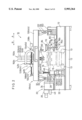
- FIG. 2 shows a side view of the tightening apparatus shown in FIG. 1;
- FIG. 3 shows a plan view of the tightening apparatus shown in FIG. 1;
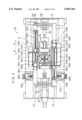
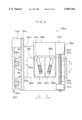
- FIG. 4 shows a front view of the tightening apparatus shown in FIG. 1;
- FIG. 5 shows a partially cross-sectional, magnified side view of a rotating mechanism of the tightening apparatus shown in FIG. 1;
- FIG. 6 shows a perspective view of a socket-holding mechanism of the tightening apparatus shown in FIG. 1;
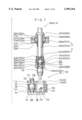
- FIG. 7 shows a partially magnified, vertical cross-sectional view of a socket exchange mechanism of the tightening apparatus shown in FIG. 1;
- FIG. 8 shows a partially magnified perspective view of an inter-axis displacement mechanism shown in FIG. 1;
- FIG. 9 shows a partially cross-sectional, magnified front view of a cam structure of the inter-axis displacement mechanism shown in FIG. 8;
- FIG. 10 shows a state of use of the socket exchange mechanism shown in FIG. 7, illustrating a partially magnified, vertical cross-sectional view in which a collar member is deflected with respect to a fitting member;
- FIG. 11 shows a state of use of the socket exchange mechanism shown in FIG. 7, illustrating a partially magnified, vertical cross-sectional view in which a socket is installed to the fitting member;
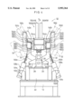
- FIG. 12 shows a state of use of the tightening apparatus shown in FIG. 1, illustrating a partially magnified front view in which connecting rod bolts are installed to a crankshaft of an L-type engine;
- FIG. 13 shows a state of use of the tightening apparatus shown in FIG. 1, illustrating a partially magnified front view in which connecting rod bolts are installed to a crankshaft of a V-type engine.
- reference numeral 10 indicates an apparatus for tightening connecting rod attachment members according to an embodiment of the present invention.
- the apparatus 10 for tightening connecting rod attachment members includes a lengthy table 12. As shown in FIG. 2, a cylinder block 15 as a workpiece is conveyed onto the table 12 by the aid of conveyer rails 13. In the cylinder block 15, pin sections of a crankshaft 14 are arranged with respect to large ends of unillustrated connecting rods.
- a rotating mechanism 20 for supporting a first end of a shaft section 16 of the crankshaft 14 and controlling rotation of the crankshaft 14 is provided on a first end side of the table 12.
- the rotating mechanism 20 includes a gear box 24 secured to a top of a pedestal member 22.
- a servomotor 26 as a rotary driving source is disposed at a first end of the gear box 24.
- a spline shaft 35 which is inserted into a cylindrical member 28, is disposed in parallel to a rotary shaft 34 of the servomotor 26, in the gear box 24.
- Arm members 32, 33 which construct an angular deflecting mechanism 30a, 30b described later on, are rotatably arranged on the cylindrical member 28.
- the spline shaft 35 penetrates through substantially cylindrical gear members 36a, 36b having teeth formed on their inner circumferences for engaging with the spline shaft 35.
- the gear members 36a, 36b are rotated together with the spline shaft 35.
- the spline shaft 35 is slidable in the axial direction (directions indicated by the arrows A and B) with respect to the gear members 36a, 36b.
- the gear members 36a, 36b are rotatably supported on support members 38a, 38b by the aid of bearing members 37a, 37b.
- a gear 39 is formed on an outer circumference of one of the gear members 36a.
- the gear 39 is meshed with a gear 40 formed on the rotary shaft 34.
- a first end of the spline shaft 35 is rotatably supported by a displacement plate 41.
- a rod member 42 is secured to the displacement plate 41 in parallel to the spline shaft 35.
- a cylinder rod 44 of a cylinder 43 is secured to the displacement plate 41.
- the cylinder 43 is secured to a support plate 45 provided vertically on the pedestal member 22.
- An engaging member 46 for engaging with the end of the shaft section 16 of the crankshaft 14 is secured to the second end of the spline shaft 35.
- the engaging member 46 has a hole 46a for engaging with the shaft section 16 of the crankshaft 14, and it has a slit 47 defined along its axial direction.
- An engaging pawl 48 which is formed in a bending manner, is disposed in the engaging member 46.
- a first end of the engaging pawl 48 is displaceable inwardly or outwardly with respect to the engaging member 46 by the aid of the slit 47.
- the engaging pawl 48 is always urged toward the hole 46a by the aid of a spring member 49, and it is bent to form an end 48a.
- a ring-shaped lock member 50 is slidably engaged with the outer circumference of the engaging member 46.
- One end of a swinging member 52 is rotatably disposed on the lock member 50.
- the swinging member 52 is rotatably supported, at its substantially central portion, by an end of the rod member 42 by the aid of an attachment member 54.
- a cylinder rod 58 of a cylinder 56 is rotatably disposed at the other end of the swinging member 52.
- the cylinder 56 is supported by the attachment member 54.
- the attachment member 54 is provided with a proximity switch 62.
- An end 48a of the engaging pawl 48 is capable of making approach and separation with respect to the proximity switch 62.
- the proximity switch 62 When the end 48a approaches the proximity switch 62 as illustrated by solid lines in FIG. 5, the proximity switch 62 generates a signal which indicates a locked state of the crankshaft 14.
- a support mechanism 70 is provided opposingly to the rotating mechanism 20, at a second end of the table 12.
- the support mechanism 70 has rail members 74 secured to the top of a pedestal member 72.
- Guide members 76a, 76b are slidably provided on the rail members 74.
- the guide members 76a, 76b are secured to a displacement member 78 formed to have a substantially L-shaped configuration.
- a horizontal section 78a of the displacement member 78 is connected to a cylinder rod 82 of a cylinder 80 secured to the pedestal member 72.
- An engaging member 84 is rotatably provided on a perpendicular section 78b of the displacement member 78.
- the engaging member 84 is engageable with a second end of the shaft section 16 of the crankshaft 14.
- a socket-holding unit 92 which forms a part of a socket exchange mechanism 90, is disposed over the perpendicular section 78b of the displacement member 78. As shown in FIG. 6, the socket-holding unit 92 has a support plate 94 secured to the top of the displacement member 78.
- a socket-accommodating member 98 which is defined with a plurality of holes 96 for accommodating sockets 95 therein, is secured to the support plate 94.
- An outer wall section of the socket-accommodating member 98 is formed to have a peak-valley configuration.
- a ball notch 100 and a proximity sensor 102 are provided corresponding to each of the plurality of holes 96.
- a ball 104 which is protrudable toward the inside of the hole 96, is provided in the ball notch 100 (see FIG. 7).
- the ball 104 is engageable with a groove 99 defined on the outer circumference of the socket 95.
- a recess 105 for engaging with a connecting rod bolt described later on is defined at a lower portion of the socket 95.
- the recess 105 engages with a projection 107 formed on the support plate 94.
- a prism-shaped fitting section 101 is formed at an upper portion of the socket 95.
- a groove 103 is defined around the circumference of the fitting section 101.
- a cylinder 106 is secured to the support plate 94.
- a plate-shaped disengaging member 110 is secured in parallel to the support plate 94 to a plurality of cylinder rods 108 for constructing the cylinder 106.
- Guide rails 112a, 112b which extend in the vertical direction, are secured to both side portions of the disengaging member 110.
- the guide rails 112a, 112b are inserted into guide members 114a, 114b which are secured to the socket-accommodating member 98.
- the disengaging member 110 is defined with a plurality of holes 116 corresponding to the plurality of holes 96 of the socket-accommodating member 98.
- the sockets 95 are feasibly inserted into the holes 116.
- arm members 122, 124 which construct the angular deflecting mechanisms 30a, 30b, are provided rotatably and coaxially with respect to the engaging member 84 via a support shaft member 120 at the end of the pedestal member 72.
- the arm members 33, 122 are bridged with a frame 126a, while the arm members 32, 124 are bridged with a frame 126b.
- ball screws 130a, 130b for constructing linear actuators (arm-deflecting mechanisms) 128a, 128b are rotatably connected to the respective frames 126a, 126b.
- the linear actuators 128a, 128b are supported swingably by support members 132a, 132b secured to the table 12.
- the linear actuators 128a, 128b are provided with servomotors 131a, 131b.
- the servomotors 131a, 131b are operated, the ball screws 130a, 130b make forward and backward displacement in the axial direction.
- axial displacement mechanisms 133a, 133b are disposed on the frames 126a, 126b.
- the axial displacement mechanisms 133a, 133b include linear actuators 135a, 135b secured along the longitudinal direction of the frames 126a, 126b.
- the linear actuators 135a, 135b have ball screws 136a, 136b provided rotatable by the aid of holding plates 134a to 134d.
- the ball screws 136a, 136b are connected to rotary shafts of servomotors 138a, 138b as rotary driving sources secured to the holding plates 134a, 134d respectively.
- the ball screws 136a, 136b are provided with displacement members 140a, 140b. When the ball screws 136a, 136b are rotated, the displacement members 140a, 140b are displaced in the direction of the arrow A or B.
- plate-shaped members 142a, 142b which are formed in a bending manner, are secured to the displacement members 140a, 140b.
- First ends of bendable cable guides 144a, 144b are secured to the ends of the plate-shaped members 142a, 142b.
- Second ends of the cable guides 144a, 144b are secured to the frames 126a, 126b by the aid of support plates 146a, 146b.
- compressed air supply pipes and cables for transmitting electric signals are installed at the inside of the cable guides 144a, 144b.
- base plates 154a, 154b which extend perpendicularly, are secured to the displacement members 140a, 140b.
- Guide members 156a to 156d are secured to the base plates 154a, 154b on their surfaces opposing to the frames 126a, 126b respectively.
- the guide members 156a to 156d are slidably engaged with the rail members 158a to 158d. Therefore, the displacement members 140a, 140b are displaceable in the direction of the arrow A or B along the rail members 158a to 158d.
- Inter-axis displacement mechanisms 150a, 150b are provided on the displacement members 140a, 140b.
- One of the inter-axis displacement mechanisms 150a includes a pair of nut runners 152a, 152b, and the other inter-axis displacement mechanism 150b includes a pair of nut runners 152c, 152d.
- inter-axis displacement mechanisms 150a One of the inter-axis displacement mechanisms 150a will be explained in detail with reference to FIG. 8. Components or parts of the other inter-axis displacement mechanism 150b constructed in the same manner as the inter-axis displacement mechanism 150a are designated by the same reference numerals affixed with a symbol "b", detailed explanation of which will be omitted.
- the inter-axis displacement mechanism 150a has a holding plate 160a which is disposed perpendicularly with respect to the base plate 154a.
- a plate-shaped member 162a is secured in parallel to the base plate 154a at an end of the holding plate 160a.
- a rail member 164a which extends in the vertical direction, is secured to the holding plate 160a.
- a guide member 166a is slidably engaged with the rail member 164a.
- a linear actuator 169a which constructs a cam displacement mechanism, is secured via a plate-shaped member 168a to the guide member 166a.
- the linear actuator 169a has a servomotor 170a. As shown in FIG.
- a ball screw 172a is coaxially attached to a rotary shaft of the servomotor 170a.
- the ball screw 172a is engaged with a displacement member 174a.
- the displacement member 174a is secured to the holding plate 160a. Accordingly, when the servomotor 170a is operated to rotate the ball screw 172a, the plate-shaped member 168a, which is secured to the servomotor 170a, is displaced in the direction of the arrow C or D.
- a cam plate 176a is secured to the plate-shaped member 168a.
- Lengthy cam holes 178a, 180a are defined through the cam plate 176a, and they are mutually inclined by predetermined angles.
- Cam members 182a, 184a are engaged with wall sections of the cam holes 178a, 180a.
- the cam members 182a, 184a are secured to guide members 186a, 188a respectively.
- Guide bars 190a, 192a which extend in the horizontal direction, are slidably inserted into the guide members 186a, 188a.
- the base plate 154a and the plate-shaped member 162a are bridged with the guide bars 190a, 192a.
- the nut runners 152a, 152b described above are secured to the guide members 186a, 188a respectively.
- the rotary driving force is transmitted to the respective nut runners 152a, 152b from unillustrated rotary transmission mechanisms accommodated in cylindrical sections 194a, 196a respectively.
- the rotary driving force is transmitted to rotary shafts 202a, 204a via gear boxes 198a, 200a.
- the rotary shafts 202a, 204a are vertically movable through the gear boxes 198a, 200a respectively.
- the rotary shafts 202a, 204a are slidably inserted into guide members 206a, 208a respectively.
- guide bars 210a, 212a are provided in an upstanding manner on the guide members 206a, 208a.
- the guide bars 210a, 212a are slidably inserted into unillustrated holes which are defined to extend vertically through the gear boxes 198a, 200a.
- the guide members 206a, 208a are engaged with substantially U-shaped slits 224a defined on a holding plate 222a. Explanation will be made in detail below with reference to FIG. 7.
- the guide members 206a, 208a are formed with step sections 218a, 220a, while the walls for forming the slits 224a are formed with step sections 225a.
- the step sections 218a, 220a are engaged with the step sections 225a to restrict downward displacement of the guide members 206a, 208a.
- a guide plate 231a which is formed to have a substantially H-shaped configuration, is secured to the top of the holding plate 222a.
- Step sections 227a, 229a of the guide members 206a, 208a are engaged with wall sections for forming recesses 226a, 228a of the guide plate 231a to restrict upward displacement of the guide members 206a, 208a.
- the guide members 206a, 208a are guided in the direction of the arrow E or F by means of the slits 224a and the recesses 226a, 228a (see FIG. 8).
- the holding plate 222a is secured to a cylinder rod 232a of a cylinder 230a.
- the cylinder 230a is secured to the base plate 154a. Therefore, when the cylinder 230a is operated, the rotary shafts 202a, 204a are displaced in the direction of the arrow C or D.
- Chucks 236a, 238a for constructing the socket exchange mechanism 90 are disposed at the lower ends of the rotary shafts 202a, 204a. As shown in FIG. 7, the chucks 236a, 238a are provided with fitting members 240a, 242a secured to the lower ends of the rotary shafts 202a, 204a. The fitting members 240a, 242a are prevented from disengagement from the rotary shafts 202a, 204a by the aid of pin members 244a, 246a. Prism-shaped holes 245a, 247a for fitting the fitting sections 101 of the sockets 95 thereto are defined in the fitting members 240a, 242a.
- First ends of coil springs 248a, 250a are seated on the top portions of the fitting members 240a, 242a. Second ends of the coil springs 248a, 250a are seated on seating members 269a, 271a secured to the bottom portions of the guide members 206a, 208a. Therefore, the chucks 236a, 238a are always urged in the direction of the arrow C.
- a plurality of holes 252 are defined in the fitting members 240a, 242a. Ball members 254 are fitted to the holes 252 respectively.
- the fitting members 240a, 242a are slidably inserted into collar members (holding members) 260a, 262a each of which is formed to have a cylindrical configuration.
- Recesses 264a, 266a are defined on the top portions of the collar members 260a, 262a.
- First ends of coil springs 268a, 270a are seated on the bottoms for forming the recesses 264a, 266a.
- Second ends of the coil springs 268a, 270a are seated on step sections 272a, 274a formed on the fitting members 240a, 242a.
- Inscribing grooves 276a, 278a are defined on the inner circumferences of the collar members 260a, 262a. When the collar members 260a, 262a are displaced in the direction of the arrow D, the grooves 276a, 278a communicates with the holes 252.
- the apparatus 10 for tightening connecting rod attachment members is basically constructed as described above. Next, its operation will be explained.
- the cylinder block 15 installed with the crankshaft 14 is conveyed onto the table 12 by the aid of the conveyer rails 13 (see FIG. 2).
- a palette for holding the cylinder block 15 is provided with an ID tag (not shown) corresponding to the type of the conveyed cylinder block 15.
- the type of the engine is distinguished by reading the ID tag by using an unillustrated reader.
- the rotating mechanism 20, the angular deflecting mechanisms 30a, 30b, the axial displacement mechanisms 133a, 133b, the inter-axis displacement mechanisms 150a, 150b, and the socket exchange mechanism 90 are controlled corresponding to the distinguished type.
- a connecting rod 280 and a connecting rod cap 282 are installed to the crankshaft 14.
- Connecting rod bolts 284 as the connecting rod attachment members are inserted into screw holes 286a, 286b defined through the connecting rod 280 and the connecting rod cap 282.
- the cylinder 43 of the rotating mechanism 20 is operated to displace the engaging member 46 in the direction of the arrow A by the aid of the spline shaft 35 and the rod member 42.
- the first end of the shaft section 16 of the crankshaft 14 is inserted and fitted into the hole 46a of the engaging member 46 (see FIG. 5).
- the cylinder 80 of the support mechanism 70 is operated to displace the displacement member 78 in the direction of the arrow B.
- the engaging member 84 is engaged with the second end of the shaft section 16 of the crankshaft 14 (FIG. 2). Accordingly, the crankshaft 14 is rotatably supported by the engaging members 46, 84.
- any crankshaft 14 having a different length can be rotatably supported by the engaging members 46, 84 by adjusting the amounts of displacement of the cylinder 43 and the cylinder 80.
- the cylinder 56 is operated to displace the lock member 50 in the direction of the arrow A so that the engaging pawl 48 and the key groove 16a are prevented from disengagement from the fitted state.
- the sockets 95 corresponding to the type of the engine are selected from the plurality of sockets 95 supported on the socket-holding unit 92, and they are installed to the chucks 236a, 236b, 238a, 238b of the nut runners 152a to 152d.
- the servomotors 138a, 138b of the axial displacement mechanisms 133a, 133b are operated to displace the inter-axis displacement mechanisms 150a, 150b in the direction of the arrow A (see FIGS. 1 and 3) so that the nut runners 152a to 152d are displaced to the positions over the socket-holding unit 92.
- the cylinder 230a When the cylinder 230a is operated to displace the holding plate 222a in the direction of the arrow C, the lower ends of the collar members 260a, 262a of the chucks 236a, 238a abut against the disengaging member 110.
- the collar members 260a, 262a make relative upward displacement with respect to the fitting members 240a, 242a in opposition to the resilient force of the coil springs 268a, 270a (see FIG. 10).
- the holes 252 of the fitting members 240a, 242a communicate with the grooves 276a, 278a of the collar members 260a, 262a.
- the ball members 254 become movable between the holes 252 and the grooves 276a, 278a.
- the socket 95 is placed on the socket-holding unit 92 as shown by two-dot chain lines in FIG. 10, and it is not installed to the chuck 236a, 238a.
- the fitting section 101 of the socket 95 is fitted to the hole 245a, 247a of the fitting member 240a, 242a.
- the ball members 254 are fitted to the groove 103 defined on the fitting section 101 (see FIG. 11).
- the cylinder 230a is operated to displace the holding plate 222a in the direction of the arrow D (see FIG. 8)
- the collar member 260a, 262a is displaced in the direction of the arrow C relatively with respect to the fitting member 240a, 242a in accordance with the resilient force of the coil spring 268a, 270a.
- the communication between the groove 276a, 278a and the hole 252 is intercepted.
- the ball members 254 protrude inwardly from the hole 252 to be fixed in a state of being fitted to the groove 103 of the socket 95 (see FIG. 7). Accordingly, the socket 95 is prevented from disengagement from the fitting member 240a, 242a by the aid of the ball members 254.
- the connecting rod is tightened to the crankshaft 14.
- the servomotor 26 of the rotating mechanism 20 is operated to deflect the crankshaft 14 at a predetermined angle (see FIG. 5).
- the linear actuators 128a, 128b of the angular deflecting mechanisms 30a, 30b are operated to rotate the arm members 32, 33, 122, 124 so that the nut runners 152a to 152d are deflected by predetermined angles with respect to the crankshaft 14 (see FIGS. 1 to 4).
- the center of rotation of the arm members 32, 33 is coaxial with the engaging member 46, and the center of rotation of the arm members 122, 124 is coaxial with the engaging member 84. Therefore, the arm members 32, 33; 122, 124 are rotated about the center of the shaft section 16 of the crankshaft 14 rotatably supported by the engaging members 46, 84. In the case of a crankshaft of the L-type engine, the arm members 32, 33, 122, 124 are rotated to position the axes of the nut runners 152a to 152d so that they extend in the vertical direction as shown by solid lines in FIG. 4.
- the arm members 32, 33, 122, 124 are rotated so that the nut runners 152a, 152b are deflected with respect to the nut runners 152c, 152d by a predetermined angle as shown by two-dot chain lines in FIG. 4.
- the inter-axis displacement mechanisms 150a, 150b are used to adjust the distance between the nut runners 152a, 152b and the distance between the nut runners 152c, 152d so that they are equal to the distance between the screw holes 286a, 286b to which the pair of connecting rod bolts 284 are fastened (see FIG. 12).
- the servomotor 170a for the inter-axis displacement mechanism 150a, 150b is operated to rotate the ball screw 172a, the plate-shaped member 168a is displaced together with the servomotor 170a in the direction of the arrow C or D, because the displacement member 174a is secured to the holding plate 160a (see FIG. 9).
- the cam plate 176a which is secured to the plate-shaped member 168a, is displaced in the direction of the arrow C or D.
- the cam members 182a, 184a are guided by the wall sections of the cam holes 178a, 180a, and the guide members 186a, 188a are displaced in the direction of the arrow E or F along the guide bars 190a, 192a. Therefore, the nut runners 152a, 152b, which are secured to the guide member 186a, 188a respectively, make mutual approach or separation. Once the nut runners 152a, 152b are disposed at a predetermined distance, the servomotor 170a is stopped.
- the force in the direction of the arrow G which is caused by the reaction generated when the connecting rod bolts 284 are fastened, is applied to the inter-axis displacement mechanism 150a via the nut runners 152a, 152b (see FIG. 4).
- the inter-axis displacement mechanism 150a is supported by the two rail members 158a, 158c and the two guide members 156a, 156c. Therefore, the inter-axis displacement mechanism 150a is not deflected in the direction of the arrow G, and there is no fear for occurrence of any error concerning the positions of the nut runners 152a, 152b. This fact is also true for the inter-axis displacement mechanism 150b.
- the connecting rod bolts 284 are fastened to the connecting rod 280 and the connecting rod cap 282 of the crankshaft 14 as described above. After that, the cylinder block 15 is conveyed to the next step along the conveyer rails 13.
- FIG. 12 is illustrative of the crankshaft 14 of the L-type engine.
- the connecting rod 280 is fastened to the crankshaft 14 such that the first pair of nut runners 152a, 152b and the second pair of nut runners 152c, 152d are deflected by the predetermined angles.
- the connecting rod 280 can be fastened to the crankshaft 14 regardless of the type of the engine. It is unnecessary to change the tightening apparatus 10 even when the type of the engine supplied to the production line is changed.
- the tightening apparatus 10 can be used for the production line for carrying multiple types in a mixed manner. Therefore, any exclusive production line for each type is unnecessary, and thus the production efficiency is improved.
- the tightening apparatus 10 includes the plurality of angular deflecting mechanisms 30a, 30b.
- Each of the angular deflecting mechanisms 30a, 30b is provided with the axial displacement mechanisms 133a, 133b having the pairs of nut runners 152a to 152d. Therefore, a plurality of pairs of connecting rods 280 can be simultaneously fastened. Accordingly, the operation time is shortened, and the production efficiency is further improved.
Abstract
Description
Claims (10)
Applications Claiming Priority (2)
| Application Number | Priority Date | Filing Date | Title |
|---|---|---|---|
| JP21323797A JP3930612B2 (en) | 1997-08-07 | 1997-08-07 | Connecting rod tightening device |
| JP9-213237 | 1997-08-07 |
Publications (1)
| Publication Number | Publication Date |
|---|---|
| US5993364A true US5993364A (en) | 1999-11-30 |
Family
ID=16635801
Family Applications (1)
| Application Number | Title | Priority Date | Filing Date |
|---|---|---|---|
| US09/126,136 Expired - Lifetime US5993364A (en) | 1997-08-07 | 1998-07-30 | Apparatus for tightening connecting rod attachment members |
Country Status (2)
| Country | Link |
|---|---|
| US (1) | US5993364A (en) |
| JP (1) | JP3930612B2 (en) |
Cited By (17)
| Publication number | Priority date | Publication date | Assignee | Title |
|---|---|---|---|---|
| WO2003022513A1 (en) * | 2001-09-05 | 2003-03-20 | Cooper Power Tools Gmbh & Co. | Screwing station |
| US20060011700A1 (en) * | 2004-07-15 | 2006-01-19 | Tim Trabandt | Vibration welding machine |
| US20060016614A1 (en) * | 2002-12-18 | 2006-01-26 | Dai Yokoyama | Wiring and piping apparatus of part mounting machine |
| US20060270539A1 (en) * | 2002-12-13 | 2006-11-30 | Matsushita Electric Industrial Co., Ltd. | Tool exchange device and tool |
| US20070253799A1 (en) * | 2006-04-27 | 2007-11-01 | Genesis Systems Group Llc | Nut runner and hexabot robot |
| EP1880794A1 (en) * | 2006-07-19 | 2008-01-23 | COMAU S.p.A. | Cell for automated assembling operations and assembling line including a plurality of these cells |
| US20080276452A1 (en) * | 2006-07-19 | 2008-11-13 | Comau S.P.A. | Cell for automated assembling operations |
| US20090139375A1 (en) * | 2007-11-30 | 2009-06-04 | Cinetic Automation Corp. | Quick change spindle |
| US20110098165A1 (en) * | 2009-10-23 | 2011-04-28 | Fuji Seiko Limited | Tool transfer system |
| US20150239079A1 (en) * | 2013-03-21 | 2015-08-27 | Boe Technology Group Co., Ltd. | Screw mounting device |
| US20160096243A1 (en) * | 2014-10-06 | 2016-04-07 | Hyundai Motor Company | Part assembling apparatus for vehicle |
| CN107443060A (en) * | 2017-08-09 | 2017-12-08 | 惠州市华阳光电技术有限公司 | A kind of LED lamp automatic lock screws apptss |
| US20180050428A1 (en) * | 2016-08-17 | 2018-02-22 | Toyota Motor Engineering & Manufacturing North America, Inc. | Engine block bearing cap removal mechanism |
| US10265816B2 (en) * | 2017-04-20 | 2019-04-23 | thyssenkrupp System Engineering AG | Automatic quick exchange tool for nutrunner sockets |
| CN109807607A (en) * | 2017-11-20 | 2019-05-28 | 中国科学院沈阳计算技术研究所有限公司 | A kind of tightening machine automatic position-changing mechanism |
| CN112276674A (en) * | 2020-10-13 | 2021-01-29 | 上海交通大学 | Precision measurement method and system for geometric motion error of rotating shaft of multi-axis numerical control machine tool |
| CN116117502A (en) * | 2023-04-17 | 2023-05-16 | 潍柴动力股份有限公司 | Crankshaft jigger device and connecting rod bolt assembling system |
Families Citing this family (5)
| Publication number | Priority date | Publication date | Assignee | Title |
|---|---|---|---|---|
| JP5505116B2 (en) * | 2010-06-16 | 2014-05-28 | いすゞ自動車株式会社 | Socket exchange device for stud assembly device |
| KR101282059B1 (en) * | 2012-04-17 | 2013-07-05 | 에스티에스 주식회사 | Apparatus for screwing using asymmetry multi-gantry |
| CN102950462B (en) * | 2012-10-29 | 2015-09-09 | 格力电器(中山)小家电制造有限公司 | A kind of electric fan regulation box assembly mounting device |
| CN109570988A (en) * | 2018-12-29 | 2019-04-05 | 昆山拓誉自动化科技有限公司 | Assembly line automatic lock screws apptss and lock silk method |
| CN112440097A (en) * | 2019-09-04 | 2021-03-05 | 张家港市欧微自动化研发有限公司 | Nut tightening and loosening device |
Citations (11)
| Publication number | Priority date | Publication date | Assignee | Title |
|---|---|---|---|---|
| US3813755A (en) * | 1973-01-05 | 1974-06-04 | Sealed Power Corp | Device for pneumatically loading piston assemblies into engine block cylinder bores |
| US3952393A (en) * | 1974-01-17 | 1976-04-27 | International Standard Electric Corporation | Machine and method for assembling pistons into engines |
| US4581812A (en) * | 1984-06-13 | 1986-04-15 | Honda Giken Kogyo Kabushiki Kaisha | Replaceable head type multi-spindle fastening apparatus |
| US4701954A (en) * | 1984-03-16 | 1987-10-20 | American Telephone And Telegraph Company, At&T Bell Laboratories | Multipulse LPC speech processing arrangement |
| JPS6321531A (en) * | 1986-07-15 | 1988-01-29 | Ricoh Co Ltd | Force detector |
| US4759108A (en) * | 1987-06-01 | 1988-07-26 | General Motors Corporation | Tooling apparatus and method for robotic or like mechanized installation of rocker arm assemblies |
| US4928377A (en) * | 1988-11-08 | 1990-05-29 | Muhr Und Bender Maschinenbau Gmbh | Machine tool |
| US5065507A (en) * | 1985-10-04 | 1991-11-19 | Honda Giken Kogyo Kabushiki Kaisha | Method for installing bearings on engine components |
| JPH04136630A (en) * | 1990-09-26 | 1992-05-11 | Eidai Co Ltd | Floor-heating panel |
| US5189785A (en) * | 1990-10-25 | 1993-03-02 | Toyota Jidosha Kabushiki Kasiha | Apparatus for inserting thrust metal inserts between cylinder block and crankshaft, by rotating crankshaft |
| JPH05318241A (en) * | 1992-05-15 | 1993-12-03 | Mitsubishi Motors Corp | Pitch changing mechanism of multi-shaft nut runner device |
-
1997
- 1997-08-07 JP JP21323797A patent/JP3930612B2/en not_active Expired - Fee Related
-
1998
- 1998-07-30 US US09/126,136 patent/US5993364A/en not_active Expired - Lifetime
Patent Citations (11)
| Publication number | Priority date | Publication date | Assignee | Title |
|---|---|---|---|---|
| US3813755A (en) * | 1973-01-05 | 1974-06-04 | Sealed Power Corp | Device for pneumatically loading piston assemblies into engine block cylinder bores |
| US3952393A (en) * | 1974-01-17 | 1976-04-27 | International Standard Electric Corporation | Machine and method for assembling pistons into engines |
| US4701954A (en) * | 1984-03-16 | 1987-10-20 | American Telephone And Telegraph Company, At&T Bell Laboratories | Multipulse LPC speech processing arrangement |
| US4581812A (en) * | 1984-06-13 | 1986-04-15 | Honda Giken Kogyo Kabushiki Kaisha | Replaceable head type multi-spindle fastening apparatus |
| US5065507A (en) * | 1985-10-04 | 1991-11-19 | Honda Giken Kogyo Kabushiki Kaisha | Method for installing bearings on engine components |
| JPS6321531A (en) * | 1986-07-15 | 1988-01-29 | Ricoh Co Ltd | Force detector |
| US4759108A (en) * | 1987-06-01 | 1988-07-26 | General Motors Corporation | Tooling apparatus and method for robotic or like mechanized installation of rocker arm assemblies |
| US4928377A (en) * | 1988-11-08 | 1990-05-29 | Muhr Und Bender Maschinenbau Gmbh | Machine tool |
| JPH04136630A (en) * | 1990-09-26 | 1992-05-11 | Eidai Co Ltd | Floor-heating panel |
| US5189785A (en) * | 1990-10-25 | 1993-03-02 | Toyota Jidosha Kabushiki Kasiha | Apparatus for inserting thrust metal inserts between cylinder block and crankshaft, by rotating crankshaft |
| JPH05318241A (en) * | 1992-05-15 | 1993-12-03 | Mitsubishi Motors Corp | Pitch changing mechanism of multi-shaft nut runner device |
Cited By (34)
| Publication number | Priority date | Publication date | Assignee | Title |
|---|---|---|---|---|
| US20050028648A1 (en) * | 2001-09-05 | 2005-02-10 | Lutz Werner Andreas | Screwing station |
| WO2003022513A1 (en) * | 2001-09-05 | 2003-03-20 | Cooper Power Tools Gmbh & Co. | Screwing station |
| US7472475B2 (en) | 2001-09-05 | 2009-01-06 | Cooper Power Tools Gmbh & Co. | Screwing station |
| US7452315B2 (en) | 2002-12-13 | 2008-11-18 | Panasonic Corporation | Tool exchange device and tool |
| US20060270539A1 (en) * | 2002-12-13 | 2006-11-30 | Matsushita Electric Industrial Co., Ltd. | Tool exchange device and tool |
| US7306551B2 (en) * | 2002-12-13 | 2007-12-11 | Matsushita Electric Industrial Co., Ltd. | Tool exchange device and tool |
| US20080058186A1 (en) * | 2002-12-13 | 2008-03-06 | Matsushita Electric Industrial Co., Ltd. | Tool exchange device and tool |
| US20060016614A1 (en) * | 2002-12-18 | 2006-01-26 | Dai Yokoyama | Wiring and piping apparatus of part mounting machine |
| US20060011700A1 (en) * | 2004-07-15 | 2006-01-19 | Tim Trabandt | Vibration welding machine |
| US20070253799A1 (en) * | 2006-04-27 | 2007-11-01 | Genesis Systems Group Llc | Nut runner and hexabot robot |
| US7673384B2 (en) * | 2006-04-27 | 2010-03-09 | Genesis Systems Group, Llc | Nut runner and hexabot robot |
| WO2008010078A2 (en) * | 2006-07-19 | 2008-01-24 | Comau S.P.A. | Cell for automated assembling operations and assembling line including a plurality of these cells |
| US20080276452A1 (en) * | 2006-07-19 | 2008-11-13 | Comau S.P.A. | Cell for automated assembling operations |
| WO2008010078A3 (en) * | 2006-07-19 | 2008-03-20 | Comau Spa | Cell for automated assembling operations and assembling line including a plurality of these cells |
| US20080016669A1 (en) * | 2006-07-19 | 2008-01-24 | Comau S.P.A. | Cell for automated assembling operations and assembling line including a plurality of these cells |
| EP1880794A1 (en) * | 2006-07-19 | 2008-01-23 | COMAU S.p.A. | Cell for automated assembling operations and assembling line including a plurality of these cells |
| US7930823B2 (en) | 2006-07-19 | 2011-04-26 | Comau S.P.A. | Cell for automated assembling operations and assembling line including a plurality of these cells |
| US7950125B2 (en) | 2006-07-19 | 2011-05-31 | Comau S.P.A. | Cell for automated assembling operations |
| US20090139375A1 (en) * | 2007-11-30 | 2009-06-04 | Cinetic Automation Corp. | Quick change spindle |
| US8366592B2 (en) * | 2007-11-30 | 2013-02-05 | Cinetic Automation Corp. | Quick change spindle |
| US20110098165A1 (en) * | 2009-10-23 | 2011-04-28 | Fuji Seiko Limited | Tool transfer system |
| US8591389B2 (en) * | 2009-10-23 | 2013-11-26 | Fuji Seiko Limited | Tool transfer system |
| US20150239079A1 (en) * | 2013-03-21 | 2015-08-27 | Boe Technology Group Co., Ltd. | Screw mounting device |
| US20160096243A1 (en) * | 2014-10-06 | 2016-04-07 | Hyundai Motor Company | Part assembling apparatus for vehicle |
| US9707648B2 (en) * | 2014-10-06 | 2017-07-18 | Hyundai Motor Company | Part assembling apparatus for vehicle |
| US20180050428A1 (en) * | 2016-08-17 | 2018-02-22 | Toyota Motor Engineering & Manufacturing North America, Inc. | Engine block bearing cap removal mechanism |
| US10265815B2 (en) * | 2016-08-17 | 2019-04-23 | Toyota Motor Engineering & Manufacturing North America, Inc. | Engine block bearing cap removal mechanism |
| US10265816B2 (en) * | 2017-04-20 | 2019-04-23 | thyssenkrupp System Engineering AG | Automatic quick exchange tool for nutrunner sockets |
| CN107443060A (en) * | 2017-08-09 | 2017-12-08 | 惠州市华阳光电技术有限公司 | A kind of LED lamp automatic lock screws apptss |
| CN109807607A (en) * | 2017-11-20 | 2019-05-28 | 中国科学院沈阳计算技术研究所有限公司 | A kind of tightening machine automatic position-changing mechanism |
| CN109807607B (en) * | 2017-11-20 | 2020-11-24 | 中国科学院沈阳计算技术研究所有限公司 | Automatic position changing mechanism of tightening machine |
| CN112276674A (en) * | 2020-10-13 | 2021-01-29 | 上海交通大学 | Precision measurement method and system for geometric motion error of rotating shaft of multi-axis numerical control machine tool |
| CN112276674B (en) * | 2020-10-13 | 2021-05-11 | 上海交通大学 | Precision measurement method and system for geometric motion error of rotating shaft of multi-axis numerical control machine tool |
| CN116117502A (en) * | 2023-04-17 | 2023-05-16 | 潍柴动力股份有限公司 | Crankshaft jigger device and connecting rod bolt assembling system |
Also Published As
| Publication number | Publication date |
|---|---|
| JPH1148053A (en) | 1999-02-23 |
| JP3930612B2 (en) | 2007-06-13 |
Similar Documents
| Publication | Publication Date | Title |
|---|---|---|
| US5993364A (en) | Apparatus for tightening connecting rod attachment members | |
| CN102189304B (en) | Device for managing electrodes for spark-machining equipment | |
| JPH0456691B2 (en) | ||
| EP0373680A2 (en) | Methods and apparatus for making electric motor parts employing pallet with removable workpiece holder | |
| US20200215621A1 (en) | Machine Tool | |
| JPH02243209A (en) | Tool adapter for spindle of machine tool | |
| US6442829B1 (en) | Production and/or assembly apparatus | |
| US10792777B2 (en) | Indexer for operating workpieces | |
| US5290121A (en) | System for the installation and replacement of components in hostile environments | |
| Boothroyd | Economics of general-purpose assembly robots | |
| US4746005A (en) | Pallet locating, clamping, rotating and transfer assembly | |
| EP1040880B1 (en) | Tool centering mechanism in punch press | |
| KR101935324B1 (en) | Mechanical working method with workpiece | |
| US20230302547A1 (en) | Chuck | |
| RU2014201C1 (en) | Flexible production module | |
| US5029388A (en) | Apparatus and process for sleeving the heat exchanger tubes of nuclear steam generators | |
| SU844208A1 (en) | Machine tool with apparatus for automatic changing of multispindle tool boxes | |
| JP5013481B2 (en) | Bolt tightening method and apparatus | |
| CN2474279Y (en) | Process flexible working equipment in box body flexible processing production line | |
| EP0906807A3 (en) | Tool-change system for a machine tool with a number of machining heads | |
| SU1604706A1 (en) | Rotary-conveyer line | |
| SU1202798A1 (en) | Loading arrangement for multioperation machine tool | |
| SU1505747A1 (en) | Metal-cutting machine tool with automatic exchange of multispindle box | |
| US6427996B1 (en) | Workpiece transfer support apparatus | |
| JP2003225836A (en) | Tool position change mechanism for automatic screw tightening equipment |
Legal Events
| Date | Code | Title | Description |
|---|---|---|---|
| AS | Assignment |
Owner name: SANYO MACHINE WORKS, LTD., JAPAN Free format text: ASSIGNMENT OF ASSIGNORS INTEREST;ASSIGNORS:MATSUURA, JUNICHI;TAKEYASU, TOSHINORI;REEL/FRAME:009364/0596 Effective date: 19980706 Owner name: HONDA GIKEN KOGYO KABUSHIKI KAISHA, JAPAN Free format text: ASSIGNMENT OF ASSIGNORS INTEREST;ASSIGNORS:MATSUURA, JUNICHI;TAKEYASU, TOSHINORI;REEL/FRAME:009364/0596 Effective date: 19980706 |
|
| STCF | Information on status: patent grant |
Free format text: PATENTED CASE |
|
| FEPP | Fee payment procedure |
Free format text: PAYOR NUMBER ASSIGNED (ORIGINAL EVENT CODE: ASPN); ENTITY STATUS OF PATENT OWNER: LARGE ENTITY |
|
| FPAY | Fee payment |
Year of fee payment: 4 |
|
| FPAY | Fee payment |
Year of fee payment: 8 |
|
| FEPP | Fee payment procedure |
Free format text: PAYER NUMBER DE-ASSIGNED (ORIGINAL EVENT CODE: RMPN); ENTITY STATUS OF PATENT OWNER: LARGE ENTITY Free format text: PAYOR NUMBER ASSIGNED (ORIGINAL EVENT CODE: ASPN); ENTITY STATUS OF PATENT OWNER: LARGE ENTITY |
|
| FPAY | Fee payment |
Year of fee payment: 12 |