EP0373680A2 - Methods and apparatus for making electric motor parts employing pallet with removable workpiece holder - Google Patents
Methods and apparatus for making electric motor parts employing pallet with removable workpiece holder Download PDFInfo
- Publication number
- EP0373680A2 EP0373680A2 EP89201042A EP89201042A EP0373680A2 EP 0373680 A2 EP0373680 A2 EP 0373680A2 EP 89201042 A EP89201042 A EP 89201042A EP 89201042 A EP89201042 A EP 89201042A EP 0373680 A2 EP0373680 A2 EP 0373680A2
- Authority
- EP
- European Patent Office
- Prior art keywords
- workpiece
- pallet
- engaging
- holder
- workpiece holder
- Prior art date
- Legal status (The legal status is an assumption and is not a legal conclusion. Google has not performed a legal analysis and makes no representation as to the accuracy of the status listed.)
- Granted
Links
Images


Classifications
-
- H—ELECTRICITY
- H02—GENERATION; CONVERSION OR DISTRIBUTION OF ELECTRIC POWER
- H02K—DYNAMO-ELECTRIC MACHINES
- H02K15/00—Methods or apparatus specially adapted for manufacturing, assembling, maintaining or repairing of dynamo-electric machines
-
- Y—GENERAL TAGGING OF NEW TECHNOLOGICAL DEVELOPMENTS; GENERAL TAGGING OF CROSS-SECTIONAL TECHNOLOGIES SPANNING OVER SEVERAL SECTIONS OF THE IPC; TECHNICAL SUBJECTS COVERED BY FORMER USPC CROSS-REFERENCE ART COLLECTIONS [XRACs] AND DIGESTS
- Y10—TECHNICAL SUBJECTS COVERED BY FORMER USPC
- Y10T—TECHNICAL SUBJECTS COVERED BY FORMER US CLASSIFICATION
- Y10T29/00—Metal working
- Y10T29/49—Method of mechanical manufacture
- Y10T29/49002—Electrical device making
- Y10T29/49009—Dynamoelectric machine
-
- Y—GENERAL TAGGING OF NEW TECHNOLOGICAL DEVELOPMENTS; GENERAL TAGGING OF CROSS-SECTIONAL TECHNOLOGIES SPANNING OVER SEVERAL SECTIONS OF THE IPC; TECHNICAL SUBJECTS COVERED BY FORMER USPC CROSS-REFERENCE ART COLLECTIONS [XRACs] AND DIGESTS
- Y10—TECHNICAL SUBJECTS COVERED BY FORMER USPC
- Y10T—TECHNICAL SUBJECTS COVERED BY FORMER US CLASSIFICATION
- Y10T29/00—Metal working
- Y10T29/53—Means to assemble or disassemble
- Y10T29/5313—Means to assemble electrical device
- Y10T29/53143—Motor or generator
- Y10T29/53161—Motor or generator including deforming means
-
- Y—GENERAL TAGGING OF NEW TECHNOLOGICAL DEVELOPMENTS; GENERAL TAGGING OF CROSS-SECTIONAL TECHNOLOGIES SPANNING OVER SEVERAL SECTIONS OF THE IPC; TECHNICAL SUBJECTS COVERED BY FORMER USPC CROSS-REFERENCE ART COLLECTIONS [XRACs] AND DIGESTS
- Y10—TECHNICAL SUBJECTS COVERED BY FORMER USPC
- Y10T—TECHNICAL SUBJECTS COVERED BY FORMER US CLASSIFICATION
- Y10T29/00—Metal working
- Y10T29/53—Means to assemble or disassemble
- Y10T29/53435—Means to assemble or disassemble including assembly pallet
-
- Y—GENERAL TAGGING OF NEW TECHNOLOGICAL DEVELOPMENTS; GENERAL TAGGING OF CROSS-SECTIONAL TECHNOLOGIES SPANNING OVER SEVERAL SECTIONS OF THE IPC; TECHNICAL SUBJECTS COVERED BY FORMER USPC CROSS-REFERENCE ART COLLECTIONS [XRACs] AND DIGESTS
- Y10—TECHNICAL SUBJECTS COVERED BY FORMER USPC
- Y10T—TECHNICAL SUBJECTS COVERED BY FORMER US CLASSIFICATION
- Y10T29/00—Metal working
- Y10T29/53—Means to assemble or disassemble
- Y10T29/53539—Means to assemble or disassemble including work conveyor
- Y10T29/53543—Means to assemble or disassemble including work conveyor including transporting track
Landscapes
- Engineering & Computer Science (AREA)
- Manufacturing & Machinery (AREA)
- Power Engineering (AREA)
- Automatic Assembly (AREA)
- Manipulator (AREA)
- Relays Between Conveyors (AREA)
- Specific Conveyance Elements (AREA)
- Manufacture Of Motors, Generators (AREA)
- Jigs For Machine Tools (AREA)
- Feeding Of Workpieces (AREA)
Abstract
Description
- This invention relates to methods and apparatus for making electric motor parts (e.g., the stators and rotors for electric motors), and more particularly to pallet systems for supporting such parts during manufacture.
- The stators and rotors for electric motor parts are typically made on highly automated assembly lines. Each stator or rotor is typically conveyed along the assembly line by positioning it on a workpiece holder. Each workpiece holder is mounted on a pallet which is the element actually engaged by the conveyor system in order to support and convey the associated stator or rotor along the assembly line. Because precise positioning of the stator or rotor relative to the machine tools located along the assembly line is required, all elements of the workpiece support system must securely engage one another so that there is no looseness or "play" in the support system. On the other hand, most assembly lines must be able to manufacture more than one size or type of motor. It would therefore be desirable to have a workpiece support system which could readily adapt to supporting motor parts of different sizes and/or types.
- In view of the foregoing, it is an object of this invention to provide a workpiece support system which both supports a workpiece securely and which can quickly and easily change to support different workpieces in an equally secure manner.
- It is another object of this invention to provide improved pallet systems for use in manufacturing electric motor parts.
- These and other objects of the invention are accomplished in accordance with the principles of the invention by providing a pallet system including a pallet member having means for supporting and releasably engaging a workpiece holder, preferably at any one of a plurality of pallet-engaging sites on the workpiece holder. The workpiece holder also preferably has a plurality of workpiece-engaging sites, each of the workpiece-engaging sites being associated with a respective one of the pallet-engaging sites so that, when the workpiece holder is engaged by the pallet at a particular pallet-engaging site, the workpiece holder can engage a workpiece at the workpiece-engaging site associated with that pallet-engaging site. When the workpiece holder is engaged by the pallet, the pallet supports the workpiece holder very securely. However, a quick release connection is used between the pallet and the workpiece holder so that the workpiece holder can be quickly removed from the pallet and either repositioned on the pallet using a different pallet-engaging site or completely replaced by another workpiece holder. Apparatus for repositioning or replacing workpiece holders as described above is also disclosed.
- Further features of the invention, its nature and various advantages will be more apparent from the accompanying drawings and the following detailed description of the preferred embodiments.
-
- FIG. 1 is an elevational sectional view of an illustrative embodiment of a pallet and workpiece holder constructed in accordance with the principles of this invention.
- FIG. 2 is a top plan view of the apparatus of FIG. 1.
- FIG. 3 is an elevational view of an illustrative embodiment of apparatus constructed in accordance with this invention for repositioning the workpiece holder of FIG. 1 on the pallet of FIG. 1 also in accordance with this invention.
- FIG. 4 is a partial plan view taken along the line 4-4 in FIG. 3.
- FIG. 5 is a simplified perspective view of an illustrative embodiment of apparatus constructed in accordance with this invention for changing the workpiece holder of FIG. 1 on the pallet of FIG. 1 also in accordance with this invention.
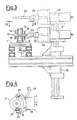
- FIG. 6 is a simplified schematic block diagram of a typical assembly line constructed in accordance with this invention.
- FIG. 7 is a schematic representation of a workpiece holder of the type shown in FIGS. 1-5.
- FIGS. 8-10 are schematic representations similar to FIG. 7 of alternative embodiments of the workpiece holder of this invention.
- The embodiment shown in FIGS. 1 and 2 has a
pallet 1 having abase plate 2 onto which is screwed a substantially cylindricalhollow part 3 which slidably receives apin 4 urged downwardly byspring 5. The portion ofpin 4 insidepart 3 has a grooved orrecessed part 6 with inclined sidewalls acting on ball 7 inside an opening 8 incylindrical part 3. - The workpiece holder comprises a
double body screws 11. Each body has aflange pins - The central part of
bodies bodies pins bodies pallet base 2. - The stator holder is automatically locked to the pallet because the inclined sidewalls of pin 4 (which is pushed downwardly by spring 5) push ball 7 outwardly of
cylindrical part 3 into thehollow part 19 of body 9 (or 10) until the ball rests insideannular groove 18. Means (described below) at various assembly line stations are provided forpush ing pin 4 up in order to disengage the stator holder fromcylindrical part 3, thus permitting its rotation in order to present the opposite body designed to accommodate the other type of stator. - FIGS. 3 and 4 show a device which can be placed at the start of an assembly line to rotate the
double body - The device includes a
gripper 20, a rotatingcylinder 21 and alinear unit 22. The device is normally in the upper position (shown in broken lines in FIG. 3). withgripper 20 open.Pallet 1 stops at a conveyor stop gate (not shown because entirely conventional and well known).Linear unit 22 goes down with thegripper jaws 23 ofgripper 20 apart. (Alternatively, the same result could be achieved by horizontal movement ofgripper 20 andcylinder 21.) Gripperjaws 23 close around the stator holder, thepins jaw 23 engaging openings inbody Cylinder 26, located under the transport system, pushespin 4 upward, thereby disengaging body 9 (or 10) as explained above.Linear unit 22 moves upward, lifting up the stator holder. In an upper position, gripper 20 rotates 180 degrees.Linear unit 22 then goes down and lowers thegrooved part 27 of the lower body ontopart 3 on the pallet.Cylinder 26 then goes back down so that the stator holder is again locked to the pallet as described above. - The present invention can also be advantageously employed in assembly lines or stators production lines featuring machines with automated re-tooling, i.e., with machines in which the tool parts designed for processing various workpieces are changed automatically.
- In such systems,
double body pneumatic cylinder 30, which lowers gripper 28 so that it can grip the workpiece holder with the same pin system asgripper 20 shown in FIG. 4.Cylinder 30 then lifts the gripper up into the position shown in FIG. 5. At the same time, on the other side of manipulator column 31 (i.e., over the transport system), when a pallet without a workpiece but with a workpiece holder 32 different from the one indicated at 29 arrives under gripper 33 which is identical to gripper 28, gripper 33 carries out the same work as gripper 28, gripping workpiece holder 32 and lifting it up away from the pallet. At this point, arm 34, operated by a rod inside column 31 and rotated by the same rotating cylinder (not shown because straightforward) located under plate 35, rotates 180 degrees, thereby reversing the positions of grippers 33 and 28. - Grippers 28 and 33 then respectively descend to the pallet and to the support on the storage unit, thereby reversing the positions of the workpiece holders.
- The store chains index in order to bring a new workpiece holder under the gripper. The pallet on the transport system moves on, leaving the place to another pallet with a workpiece holder to be changed.
- In this way the workpiece holders of all pallets on the line will be replaced by workpiece holders from the storage unit.
- The workpiece holders on the pallets are locked in place in the same amnner as shown in FIG. 3; while on the storage unit, the workpiece holders are loosely fitted over a reference pin on the support.
- FIG. 6 shows part of an illustrative embodiment of an electric motor assembly line constructed in accordance with this invention.
Endless conveyor 40conveys pallets 1 in the direction indicated byarrows 42.Element 50 may be storage unit apparatus of the type shown in FIG. 5 for selectively replacing the workpiece holder on a pallet atposition 1a.Element 52 may be workpiece holder inverter apparatus of the type shown in FIGS. 3 and 4 for selectively inverting the workpiece holder on a pallet atposition 1c. Atposition 1d, an electric motor part 56 (e.g., a stator or rotor) supplied viaconveyor 58 is put on the workpiece holder onpallet 1d byconventional element 54.Elements position 1d contains the workpiece holder appropriate for holding aworkpiece 56 and that that workpiece holder is also properly oriented for receiving such a workpiece.Conventional element 60 performs any conventional manufacturing step on the workpiece on the pallet atposition 1f.Conventional element 62 performs another conventional manufacturing step on the workpiece on the pallet atposition 1g. Atposition 1h,conventional element 62 removes the completedworkpiece 56′ from the pallet and conveys it away viaconveyor 66. The empty pallets and workpiece holders are returned to the start of the assembly line for reuse. - Although in the embodiments shown in FIGS. 1-6 each workpiece holder (abstracted as element WH in FIG. 7) includes two pallet-engaging sites PES1 and PES2 respectively associated with two workpiece-engaging sites WES1 and WES2, this is not necessarily the case, and the workpiece holders of this invention can have other numbers of pallet- and workpiece-engaging sites if desired. For example, FIG. 8 shows a workpiece holder WH having only one pallet-engaging site PES1 and one opposite workpiece-engaging site WES1. Such workpiece holders could be used with apparatus of the type shown in FIG. 5 to enable an assembly line to process differently configured workpieces. As another example, FIG. 9 shows a workpiece holder WH having three pallet-engaging sites PES1-PES3, each of which is associated with a respective one of three workpiece-engaging sites WES1-WES3. Similarly, FIG. 10 shows a workpiece holder WH having four pallet-engaging sites PES1-PES4, each of which is associated with a respective one of four workpiece-engaging sites WES1-WES4.
Claims (38)
a pallet member;
a workpiece holder having at least one pallet-engaging site and at least one workpiece-engaging site; and
means disposed on said pallet member for releasably engaging said workpiece holder at said pallet-engaging site so that said workpiece holder can hold a workpiece at said workpiece-engaging site.
a cam member reciprocable along a reciprocation axis substantially parallel to the axis along which said first and second members are telescopically engageable, said cam member having a cam surface which is mutually transverse to said locking and reciprocation axes for engaging said third member; and
spring means for resiliently urging said cam member to move parallel to said reciprocation axis in the direction which will cause said third member to extend from said aperture into said other of said first and second members.
a pallet member;
a workpiece holder having a plurality of pallet-engaging sites and a plurality of workpiece-engaging sites, each of said workpiece-engaging sites being associated with a respective one of said pallet-engaging sites; and
means disposed on said pallet member for releasably engaging said workpiece holder at any one of said pallet-engaging sites so that said workpiece holder can hold a workpiece at the workpiece-engaging site associated with the one of said pallet-engaging sites at which said means for releasably engaging engages said workpiece holder.
a cam member reciprocable along a reciprocation axis substantially parallel to the axis along which said first and second members are telescopically engageable, said cam member having a cam surface which is mutually transverse to said locking and reciprocation axes for engaging said third member; and
spring means for resiliently urging said cam member to move parallel to said reciprocation axis in the direction which will cause said third member to extend from said aperture into said other of said first and second members.
a pallet member;
storage means for storing a plurality of workpiece holders, each of said workpiece holders having at least one pallet-engaging site and at least one workpiece-engaging site adapted to hold workpieces having a predetermined configuration;
means disposed on said pallet for releasably engaging any of said workpiece holders at the pallet-engaging site of the engaged workpiece holder so that the engaged workpiece holder can hold a workpiece at its workpiece-engaging site;
means for selectively operating said means for releasably engaging to release a workpiece holder from said pallet;
means for removing the released workpiece holder from said pallet and storing it in said storage means; and
means for removing a workpiece holder from said storage means and positioning it on said pallet for engagement by said means for releasably engaging.
a pallet member;
a workpiece holder having at least two pallet-engaging sites and at least two workpiece- engaging sites, each of said workpiece-engaging sites being associated with a respective one of said pallet-engaging sites, and each of said workpiece-engaging sites being adapted to hold a workpiece having a predetermined configuration;
means disposed on said pallet member for releasably engaging said workpiece holder at either one of said pallet-engaging sites so that said workpiece holder can hold a workpiece at the workpiece-engaging site associated with the pallet-engaging site at which said means for releasably engaging engages said workpiece holder;
means for selectively operating said means for releasably engaging to release said workpiece holder from said pallet; and
means for repositioning the released workpiece holder relative to said pallet member so that said means for releasably engaging can engage said workpiece holder at the other one of said pallet engaging sites.
providing a pallet member;
providing a workpiece holder having at least one pallet-engaging site and at least one workpiece-engaging site, said pallet including means for releasably engaging said workpiece holder at said pallet-engaging site so that said workpiece holder can hold a workpiece at the workpiece-engaging site;
positioning said workpiece on said workpiece holder at said workpiece-engaging site;
processing said workpiece while it is on said workpiece holder to produce said electric motor part; and
removing said electric motor part from said workpiece holder.
selecting said workpiece holder from a plurality of workpiece holders, each of which has at least one pallet-engaging site and at least one workpiece-engaging site adapted to hold a workpiece having a predetermined configuration;
and positioning the selected workpiece holder for engagement by said pallet member if the selected workpiece holder is not already engaged by said pallet member.
removing any workpiece holder from engagement with said pallet member if the workpiece holder in engagement with said pallet member is not the selected workpiece holder.
selecting the workpiece-engaging site on said workpiece holder which is adapted to hold a workpiece having the configuration to be processed; and
positioning the workpiece holder for engagement by said pal let member at the pallet- engaging site associated with the selected workpiece-engaging site.
Applications Claiming Priority (2)
| Application Number | Priority Date | Filing Date | Title |
|---|---|---|---|
| IT6811388 | 1988-12-16 | ||
| IT8868113A IT1234229B (en) | 1988-12-16 | 1988-12-16 | METHODS AND EQUIPMENT FOR MAKING PARTS OF ELECTRIC MOTORS USING PALLETS WITH REMOVABLE SUPPORT OF THE WORKPIECE |
Publications (3)
| Publication Number | Publication Date |
|---|---|
| EP0373680A2 true EP0373680A2 (en) | 1990-06-20 |
| EP0373680A3 EP0373680A3 (en) | 1991-06-12 |
| EP0373680B1 EP0373680B1 (en) | 1994-11-30 |
Family
ID=11307941
Family Applications (1)
| Application Number | Title | Priority Date | Filing Date |
|---|---|---|---|
| EP89201042A Expired - Lifetime EP0373680B1 (en) | 1988-12-16 | 1989-04-24 | Methods and apparatus for making electric motor parts employing pallet with removable workpiece holder |
Country Status (5)
| Country | Link |
|---|---|
| US (2) | US4965924A (en) |
| EP (1) | EP0373680B1 (en) |
| JP (1) | JPH02163214A (en) |
| DE (1) | DE68919655T2 (en) |
| IT (1) | IT1234229B (en) |
Cited By (3)
| Publication number | Priority date | Publication date | Assignee | Title |
|---|---|---|---|---|
| FR2736855A1 (en) * | 1995-07-20 | 1997-01-24 | Asmo Co Ltd | ELEMENT ASSEMBLED IN A ASSEMBLY CHAIN |
| WO2004078408A1 (en) * | 2003-03-05 | 2004-09-16 | Koch Packaging Machines, L.P. | Workpiece manipulation system and method for the manipulation of workpieces along a conveyor belt |
| CN109110471A (en) * | 2018-10-30 | 2019-01-01 | 浙江薪人机电科技有限公司 | Rotor automatic coil winding machine material feed system and method |
Families Citing this family (19)
| Publication number | Priority date | Publication date | Assignee | Title |
|---|---|---|---|---|
| US5208966A (en) * | 1989-04-06 | 1993-05-11 | Honda Giken Kogyo Kabushiki Kaisha | Apparatus for assembling door handle |
| JPH04343631A (en) * | 1991-01-25 | 1992-11-30 | Seiko Epson Corp | Part assembling device |
| US5261264A (en) * | 1991-06-11 | 1993-11-16 | The Boeing Company | Automated forming station |
| US5348142A (en) * | 1993-07-26 | 1994-09-20 | Odawara Engineering Co., Ltd. | Adjustable pallet |
| FR2719569B1 (en) * | 1994-05-03 | 1996-07-19 | Sapal Plieuses Automatiques | Pendulum storage facility. |
| BR9600257A (en) * | 1995-01-31 | 1997-12-23 | Johnson & Johnson | Apparatus for supporting a wound coil core and a rear end of a wound wire and method for storing and retrieving a wound coil core and a rear end of a wound wire |
| US5685413A (en) * | 1995-09-12 | 1997-11-11 | Odawara Automation, Inc. | Adjustable pallet for supporting work pieces |
| US5662317A (en) * | 1995-09-18 | 1997-09-02 | Globe Products Inc. | Pallet support assembly for use in manufacturing stators |
| US5926941A (en) * | 1996-07-23 | 1999-07-27 | Axis Usa, Inc. | Armature pallet |
| US5735219A (en) * | 1996-11-27 | 1998-04-07 | Odawara Automation, Inc. | Open base adjustable pallet for supporting work pieces |
| DE69813993D1 (en) * | 1997-10-29 | 2003-06-05 | Axis Spa | Device and method for manufacturing fittings |
| JP2001251817A (en) * | 2000-03-07 | 2001-09-14 | Moric Co Ltd | Assembling device for permanent magnet field motor |
| US6732971B2 (en) | 2000-07-13 | 2004-05-11 | Axis U.S.A., Inc. | Apparatus and methods for winding and transferring dynamoelectric machine stators |
| DE10064913A1 (en) * | 2000-12-23 | 2002-07-18 | Siemens Ag | Alignment procedure of anchors |
| US6789659B2 (en) | 2001-08-22 | 2004-09-14 | Odawara Automation, Inc. | Stator winding system and method with pallet on pallet arrangement |
| DE102005040165A1 (en) * | 2005-08-25 | 2007-03-01 | Bosch Rexroth Aktiengesellschaft | Device for transporting workpiece carriers |
| JP5615129B2 (en) * | 2010-10-21 | 2014-10-29 | 三菱重工業株式会社 | Clamping device |
| JP5785031B2 (en) * | 2011-08-22 | 2015-09-24 | 株式会社松浦機械製作所 | Pallet changing system and machining center equipped with the system |
| DE102019211859A1 (en) * | 2019-08-07 | 2021-02-11 | Felsomat Gmbh & Co. Kg | Manufacturing system and method for manufacturing a stator with rod conductors |
Citations (4)
| Publication number | Priority date | Publication date | Assignee | Title |
|---|---|---|---|---|
| DE3330687A1 (en) * | 1983-08-25 | 1985-03-14 | Micafil AG, Zürich | Device for the automatic manufacture of armatures for small electrical motors, and a method for operation of the same |
| JPS6119534A (en) * | 1984-07-09 | 1986-01-28 | Toshiba Corp | Preparation device |
| EP0210669A1 (en) * | 1985-07-26 | 1987-02-04 | AXIS S.p.A. | Pallet, advancing on conveyor belts along a line for the processing of stators and rotors of electrical motors, on which said elements are assembled as couples |
| EP0215353A2 (en) * | 1985-09-17 | 1987-03-25 | Gildemeister AG | Changing device for jaws |
Family Cites Families (4)
| Publication number | Priority date | Publication date | Assignee | Title |
|---|---|---|---|---|
| JPS57211439A (en) * | 1981-06-22 | 1982-12-25 | Sony Corp | Automatic assembly device |
| CH660819A5 (en) * | 1983-08-22 | 1987-06-15 | Micafil Ag | DEVICE FOR THE AUTOMATIC MANUFACTURING OF ANCHORS FOR SMALL ELECTRIC MOTORS AND A METHOD FOR OPERATING THE SAME. |
| DE3680967D1 (en) * | 1985-07-11 | 1991-09-26 | Axis Spa | PRODUCTION LINE FOR RANGE OF RACKS OF ELECTRIC MOTORS. |
| GB8517771D0 (en) * | 1985-07-15 | 1985-08-21 | Black & Decker Inc | Electric motors |
-
1988
- 1988-12-16 IT IT8868113A patent/IT1234229B/en active
-
1989
- 1989-03-20 US US07/326,012 patent/US4965924A/en not_active Expired - Lifetime
- 1989-03-22 JP JP1067739A patent/JPH02163214A/en active Pending
- 1989-04-24 DE DE68919655T patent/DE68919655T2/en not_active Expired - Fee Related
- 1989-04-24 EP EP89201042A patent/EP0373680B1/en not_active Expired - Lifetime
-
1990
- 1990-10-01 US US07/591,272 patent/US5065499A/en not_active Expired - Lifetime
Patent Citations (4)
| Publication number | Priority date | Publication date | Assignee | Title |
|---|---|---|---|---|
| DE3330687A1 (en) * | 1983-08-25 | 1985-03-14 | Micafil AG, Zürich | Device for the automatic manufacture of armatures for small electrical motors, and a method for operation of the same |
| JPS6119534A (en) * | 1984-07-09 | 1986-01-28 | Toshiba Corp | Preparation device |
| EP0210669A1 (en) * | 1985-07-26 | 1987-02-04 | AXIS S.p.A. | Pallet, advancing on conveyor belts along a line for the processing of stators and rotors of electrical motors, on which said elements are assembled as couples |
| EP0215353A2 (en) * | 1985-09-17 | 1987-03-25 | Gildemeister AG | Changing device for jaws |
Non-Patent Citations (1)
| Title |
|---|
| PATENT ABSTRACTS OF JAPAN vol. 010, no. 167 (M-488) 13 June 1986, & JP-A-61 019534 (TOSHIBA K.K.) 28 January 1986, * |
Cited By (3)
| Publication number | Priority date | Publication date | Assignee | Title |
|---|---|---|---|---|
| FR2736855A1 (en) * | 1995-07-20 | 1997-01-24 | Asmo Co Ltd | ELEMENT ASSEMBLED IN A ASSEMBLY CHAIN |
| WO2004078408A1 (en) * | 2003-03-05 | 2004-09-16 | Koch Packaging Machines, L.P. | Workpiece manipulation system and method for the manipulation of workpieces along a conveyor belt |
| CN109110471A (en) * | 2018-10-30 | 2019-01-01 | 浙江薪人机电科技有限公司 | Rotor automatic coil winding machine material feed system and method |
Also Published As
| Publication number | Publication date |
|---|---|
| US4965924A (en) | 1990-10-30 |
| IT8868113A0 (en) | 1988-12-16 |
| US5065499A (en) | 1991-11-19 |
| DE68919655D1 (en) | 1995-01-12 |
| EP0373680B1 (en) | 1994-11-30 |
| EP0373680A3 (en) | 1991-06-12 |
| IT1234229B (en) | 1992-05-06 |
| DE68919655T2 (en) | 1995-06-14 |
| JPH02163214A (en) | 1990-06-22 |
Similar Documents
| Publication | Publication Date | Title |
|---|---|---|
| EP0373680B1 (en) | Methods and apparatus for making electric motor parts employing pallet with removable workpiece holder | |
| US4587716A (en) | Machine tool center with multipurpose robot assembly for loading and unloading tooling and workpieces from machine tool | |
| US4679286A (en) | Multiface machining machine tool | |
| US5240235A (en) | Apparatus for making electric motor parts employing pallet with removable workpiece holder | |
| GB2257082A (en) | Turret press tool changer | |
| EP3061542A2 (en) | Forging machine with robotic handler | |
| WO1991004127A1 (en) | Modular multi-fixturing system for a machine tool | |
| EP2127802B1 (en) | Tool changer for machine tool | |
| JPH0460776B2 (en) | ||
| CN215616695U (en) | Automatic tool changing device | |
| US4833770A (en) | Flexible manufacturing system for machining workpieces | |
| EP0811463B1 (en) | Mobile rest equipment for a workpiece with variable distance support arms for automatic production lines | |
| EP0142850B1 (en) | Machine tool with two tool changers | |
| JPS62832Y2 (en) | ||
| JP2639700B2 (en) | Work supply and recovery device for machine tools | |
| JPS6047052B2 (en) | Tool changing device | |
| JPH0236054A (en) | Rotary/transfer device | |
| JPH0569908A (en) | Work automatically aligning and housing device | |
| JP4278467B2 (en) | Machine Tools | |
| JPH06190616A (en) | Jaw replacing device and robot hand at turning center | |
| JPH0242620B2 (en) | ||
| JP2537649Y2 (en) | Work pallet holding device for machine tools | |
| JP2626723B2 (en) | Automatic tool changer | |
| JPS63196344A (en) | Machine tool | |
| JPH07132332A (en) | Punch press and method for attaching die |
Legal Events
| Date | Code | Title | Description |
|---|---|---|---|
| PUAI | Public reference made under article 153(3) epc to a published international application that has entered the european phase |
Free format text: ORIGINAL CODE: 0009012 |
|
| AK | Designated contracting states |
Kind code of ref document: A2 Designated state(s): CH DE ES FR GB IT LI NL SE |
|
| PUAL | Search report despatched |
Free format text: ORIGINAL CODE: 0009013 |
|
| AK | Designated contracting states |
Kind code of ref document: A3 Designated state(s): CH DE ES FR GB IT LI NL SE |
|
| 17P | Request for examination filed |
Effective date: 19910719 |
|
| 17Q | First examination report despatched |
Effective date: 19930114 |
|
| GRAA | (expected) grant |
Free format text: ORIGINAL CODE: 0009210 |
|
| AK | Designated contracting states |
Kind code of ref document: B1 Designated state(s): CH DE ES FR GB IT LI NL SE |
|
| PG25 | Lapsed in a contracting state [announced via postgrant information from national office to epo] |
Ref country code: NL Effective date: 19941130 Ref country code: FR Effective date: 19941130 Ref country code: ES Free format text: THE PATENT HAS BEEN ANNULLED BY A DECISION OF A NATIONAL AUTHORITY Effective date: 19941130 |
|
| REF | Corresponds to: |
Ref document number: 68919655 Country of ref document: DE Date of ref document: 19950112 |
|
| ITF | It: translation for a ep patent filed |
Owner name: BARZANO'E ZANARDO S.P.A. |
|
| PG25 | Lapsed in a contracting state [announced via postgrant information from national office to epo] |
Ref country code: SE Effective date: 19950228 |
|
| PG25 | Lapsed in a contracting state [announced via postgrant information from national office to epo] |
Ref country code: GB Effective date: 19950424 |
|
| EN | Fr: translation not filed | ||
| NLV1 | Nl: lapsed or annulled due to failure to fulfill the requirements of art. 29p and 29m of the patents act | ||
| PLBE | No opposition filed within time limit |
Free format text: ORIGINAL CODE: 0009261 |
|
| STAA | Information on the status of an ep patent application or granted ep patent |
Free format text: STATUS: NO OPPOSITION FILED WITHIN TIME LIMIT |
|
| 26N | No opposition filed | ||
| GBPC | Gb: european patent ceased through non-payment of renewal fee |
Effective date: 19950424 |
|
| PGFP | Annual fee paid to national office [announced via postgrant information from national office to epo] |
Ref country code: CH Payment date: 20010420 Year of fee payment: 13 |
|
| PGFP | Annual fee paid to national office [announced via postgrant information from national office to epo] |
Ref country code: DE Payment date: 20010622 Year of fee payment: 13 |
|
| PG25 | Lapsed in a contracting state [announced via postgrant information from national office to epo] |
Ref country code: LI Free format text: LAPSE BECAUSE OF NON-PAYMENT OF DUE FEES Effective date: 20020430 Ref country code: CH Free format text: LAPSE BECAUSE OF NON-PAYMENT OF DUE FEES Effective date: 20020430 |
|
| PG25 | Lapsed in a contracting state [announced via postgrant information from national office to epo] |
Ref country code: DE Free format text: LAPSE BECAUSE OF NON-PAYMENT OF DUE FEES Effective date: 20021101 |
|
| REG | Reference to a national code |
Ref country code: CH Ref legal event code: PL |
|
| PG25 | Lapsed in a contracting state [announced via postgrant information from national office to epo] |
Ref country code: IT Free format text: LAPSE BECAUSE OF NON-PAYMENT OF DUE FEES;WARNING: LAPSES OF ITALIAN PATENTS WITH EFFECTIVE DATE BEFORE 2007 MAY HAVE OCCURRED AT ANY TIME BEFORE 2007. THE CORRECT EFFECTIVE DATE MAY BE DIFFERENT FROM THE ONE RECORDED. Effective date: 20050424 |