US5992516A - Well string injector - Google Patents
Well string injector Download PDFInfo
- Publication number
- US5992516A US5992516A US08/889,571 US88957197A US5992516A US 5992516 A US5992516 A US 5992516A US 88957197 A US88957197 A US 88957197A US 5992516 A US5992516 A US 5992516A
- Authority
- US
- United States
- Prior art keywords
- well string
- clamp
- frame
- gripping
- injector
- Prior art date
- Legal status (The legal status is an assumption and is not a legal conclusion. Google has not performed a legal analysis and makes no representation as to the accuracy of the status listed.)
- Expired - Lifetime
Links
- 230000004888 barrier function Effects 0.000 claims abstract description 9
- 238000009826 distribution Methods 0.000 claims abstract description 7
- 239000012530 fluid Substances 0.000 description 18
- 239000000047 product Substances 0.000 description 11
- 238000003860 storage Methods 0.000 description 8
- 230000007246 mechanism Effects 0.000 description 5
- 238000000034 method Methods 0.000 description 3
- NJPPVKZQTLUDBO-UHFFFAOYSA-N novaluron Chemical compound C1=C(Cl)C(OC(F)(F)C(OC(F)(F)F)F)=CC=C1NC(=O)NC(=O)C1=C(F)C=CC=C1F NJPPVKZQTLUDBO-UHFFFAOYSA-N 0.000 description 3
- 238000010276 construction Methods 0.000 description 2
- 241000557624 Nucifraga Species 0.000 description 1
- 125000004122 cyclic group Chemical group 0.000 description 1
- 238000004519 manufacturing process Methods 0.000 description 1
- 239000000463 material Substances 0.000 description 1
- 238000012986 modification Methods 0.000 description 1
- 230000004048 modification Effects 0.000 description 1
- 230000035515 penetration Effects 0.000 description 1
- 230000002028 premature Effects 0.000 description 1
- 238000012163 sequencing technique Methods 0.000 description 1
- 239000013589 supplement Substances 0.000 description 1
- 230000000153 supplemental effect Effects 0.000 description 1
Images


Classifications
-
- E—FIXED CONSTRUCTIONS
- E21—EARTH OR ROCK DRILLING; MINING
- E21B—EARTH OR ROCK DRILLING; OBTAINING OIL, GAS, WATER, SOLUBLE OR MELTABLE MATERIALS OR A SLURRY OF MINERALS FROM WELLS
- E21B19/00—Handling rods, casings, tubes or the like outside the borehole, e.g. in the derrick; Apparatus for feeding the rods or cables
- E21B19/22—Handling reeled pipe or rod units, e.g. flexible drilling pipes
Definitions
- This invention relates to apparatus and methods for injecting coilable product such as coiled tubing and coiled rods into wells.
- Gripper blocks have been used with continuous chain gripper systems that do not damage well string. Gripper blocks have also been used that have optimized stress distribution. Distribution due to the use of plural grooves in the face of the gripping dies, in which successive grooves deepen in the direction of tension.
- the inventor has proposed a well string injector in which the gripping advantages of the continuous chain gripper systems are combined with the simplicity and fewer moving parts of the stepper systems.
- a well string injector comprising a frame, with a guide at one end for guiding well string along the frame and a support at the other end for directing the well string towards a target. At least one of a pair of longitudinally spaced clamps is movable with respect to the other and at least one clamp is oriented on the frame to provide clamping forces on well string by relative movement between clamping members predominantly in a transverse direction perpendicular to the frame longitudinal direction.
- the clamping members carry gripping dies, a first one of the clamping members is adjustable secured to the frame and the other of the clamping members is adjustably secured to the first one of the clamping members.
- the clamping members may be formed of a cylinder and piston combination, the cylinder having an open and closed end, with a first gripping die on the closed end of the cylinder, arms extending from the piston on both sides of the cylinder, beyond the first gripping die, and a second gripping die mounted between the ends of the arms in a position opposed to the first gripping die.
- the clamping members may be pivotally mounted with respect to each other for movement about a pivot; and a force applicator may be attached at respective first and second points of attachment to each of the clamping members for applying force to the clamping members.
- the pivot is between the first and second well string gripping dies and the respective points of attachment of the force applicator to the clamping members.
- a third well string gripping die may be carried by the clamp for location between parallel spaced well string clamped by the clamp.
- a well string gripping die is provided, particularly in combination with the clamps described, that includes a gripping surface that induces an optimized stress distribution in well string clamped by the gripping die when the well string is in tension.
- a well string gripping die is provided, particularly in combination with the clamps described, that includes one and preferably a pair of barrier walls for preventing walk out of well string.
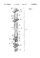
- FIG. 1 is a perspective view of a well string injector according to the invention, using a double hollow rod cylinder for moving upper and lower well string gripping clamps on the frame with respect to each other;
- FIG. 1A is a perspective view of a well string injector according to the invention, using two pairs of double cylinders for moving upper and lower well string gripping clamps on the frame with respect to each other;
- FIG. 2 is a perspective view of a well string injector according to the invention, using a single hollow rod cylinder for moving upper and lower well string gripping clamps on the frame with respect to each other;
- FIG. 3 is a perspective view of a well string injector according to the invention, using a double cylinder for moving upper and lower well string gripping clamps on the frame with respect to each other;
- FIG. 4 is a perspective view of a well string injector according to the invention with associated storage and transportation apparatus, the storage apparatus being shown in operational position;
- FIG. 5 is a perspective view of a well string injector according to the invention with a frame mounted for servicing slanted wells;
- FIG. 6 is a perspective view of a well string injector according to the invention including storage reel mounted on transportation apparatus;
- FIGS. 7A-7C are perspective views showing a storage reel in closed (FIG. 7A), intermediate (FIG. 7B) and open positions (FIG. 7C);
- FIG. 7D is a top view of the central pivot and arm restraint for the storage reel of FIGS. 7A-7C;
- FIG. 8 is a plan view of a clamp, in open position, for use with a well string injector according to the invention.
- FIG. 9 is a perspective view of a clamp, in open position, for use with a well string injector according to the invention.
- FIG. 10 is a plan view of a clamp, in closed position, for use with a well string injector according to the invention.
- FIG. 11 is a perspective view of a clamp, in closed position, for use with a well string injector according to the invention.
- FIG. 12 is a side view of a clamp, in open position, for use with a well string injector according to the invention.
- FIGS. 12A, 12B and 12C are respectfully cross-sections along the lines 12A, 12B and 12C in FIG. 12.
- FIG. 13 is a side view of a clamp, in closed position, for use with a well string injector according to the invention.
- FIG. 14 is an end view (piston end) of a clamp for use with a well string injector according to the invention.
- FIG. 15 is an end view (clamping end) of a clamp for use with a well string injector according to the invention.
- FIG. 16 is a section through a clamp, in closed position, for use with a well string injector according to the invention.
- FIG. 17 is a plan view of an open sided clamp for use with a well string injector according to the invention.
- FIG. 18 is a side view of an open sided clamp, for use with a well string injector according to the invention.
- FIGS. 19A-19D are schematics showing possible clamp configurations for use with the invention.
- FIG. 20 is a perspective view of a well string gripping die according to an aspect of the invention.
- FIG. 21A is a section through a well string gripping die according to an aspect of the invention.
- FIG. 21B shows stress distribution along the well string gripping die of FIG. 21A in use
- FIG. 22 is a longitudinal section through gripping dies in open position used to clamp parallel tubing strings
- FIG. 23 is a cross-section through gripping dies in open position used to clamp parallel tubing strings
- FIG. 24 is a longitudinal section through gripping dies in closed position used to clamp parallel tubing strings
- FIG. 25 is a cross-section through gripping dies in closed position used to clamp parallel tubing strings
- FIG. 26 is a schematic showing exemplary hydraulics for use with a well string injector according to the invention.
- FIGS. 27A and 27B show respectively two side views of an auxiliary ram for use in unseating stuck well string
- FIGS. 27C and 27D are top views of a clamp on top of the auxiliary ram of FIGS. 27A and 27B in closed and open positions respectively.
- the well string injector 10 is formed of a frame 14 secured to the wellhead 12 as by bolting.
- the frame 14 is formed of a pair of tubular members 16 bolted between lower and upper beams 18, 20 respectively at opposed frame ends of the frame 14.
- Lower beam 18 is secured to the wellhead 12.
- Upper beam 20 supports a guide structure 22 that is formed of a beam 24 secured to the upper beam 20 by tubular members 26.
- a coilable product guide 28 of conventional construction.
- Guide 28 may be one piece or foldable.
- a lower clamp 30 is secured to the lower beam 18 as by bolting.
- An upper clamp 32 is mounted on the frame 14 by double acting cylinder 34 with lower rod 36 and upper rod 38.
- the cylinder 34 is mounted along a longitudinal axis AB of frame 14, such that the upper clamp 32 is movable longitudinally along the frame 14.
- Rods 36 and 38 are hollow for receiving a well string, such as well tubing or rod, which may be continuous or jointed.
- Cylinder 34 has an annular piston for actuating the rods 36 and 38. As shown in FIG. 2, the upper rod 38 and the beam 24 may be omitted and the coilable product guide 28 connected directly to the upper beam 20. The rods 36 and 38 may thus be moved by the actuation of the cylinder 34 upwards and downwards as indicated by the double arrow AB.
- both clamps 30 and 32 mounted on hydraulic cylinders as shown in FIG. 1A.
- clamp 30 is mounted for longitudinal movement on cylinders 34A
- clamp 32 is mounted for longitudinal movement on cylinders 34.
- the well string injector of FIG. 1A is constructed in the same manner as the well string injector of FIG. 1.
- one of the clamps is shown as being fixed.
- both clamps are movable with respect to the frame. When both clamps are movable, the speed of the arrangement may be doubled.
- FIG. 2 A further embodiment of a mechanism used to move the clamps 30 and 32 longitudinally on the frame 14 with respect to each other is shown in FIG. 2.
- the frame 14 has the same constructions as in FIG. 1, except that only one rod 36 is used in double acting cylinder 34.
- guide 28 may be connected directly to the beam 20 over the end of the cylinder 34.
- FIG. 3 A further embodiment of a mechanism used to move the clamps 30 and 32 longitudinally on the frame 14 is shown in FIG. 3.
- the tubular members 16 are placed at diagonally opposed corners of the upper plate 39 of lower beam 18, and the upper clamp 32 is mounted on an intermediate beam 40, which is movable longitudinally on the frame by double acting cylinders 42 mounted on the lower beam 18.
- the upper clamps 32 shown in FIGS. 1, 2 and 3 are secured to the rod 36 (FIGS. 1, 2) and the beam 40 (FIG. 3) in a clamp sub-frame 44 consisting of spaced parallel upper and lower pairs of I-beams secured to each other by flat bars 46.
- the well string injector of FIGS. 1-3 may be located over a well 12, or other target, using a height adjustable platform 50 formed of base 52 and ground engaging supports 54.
- Well string 56 such as coilable product, is guided through guide 28 to the well string injector.
- a storage mechanism for the well string 56 is provided by rack or carousel 60.
- Both the well string injector 10 and carousel 60 may be transported on truck 70, as shown in FIG. 6. Where a well is slanted, the well string injector 10 may be supported at an angle anywhere from 0° to 90° by frame members 81 and 83 shown in FIG. 5.
- the carousel 60 is formed of a central spool 62 with arms 64 pivotally attached to and extending outward from the spool 62.
- Two arms 64A are fixed respectively to the upper and lower flanges 63 and 65 of spool 62 at diametrically opposed fixed points 66 shown for the upper flange 63 in FIG. 7D.
- the other arms 64 are pivotally attached at pivot points 68 also shown in FIG. 7D to both the upper and lower flanges 63 and 65.
- the arms 64, 64A comprise upper and lower arm rods that converge at their outer ends, such that the upper and lower rods and the spool 62 form triangular arms.
- each arm At the outer extremity of each arm is a U-shaped channel 67 for receiving the well string.
- the spool 62 rotates on base 69.
- One part 61 of the base 69 extends to the outer edge of the arms to act as a guide for guiding the well string into the U-shaped channels 67.
- the guide part 61 is fixed in relation to the arms 64, 64A.
- the arms 64, 64A When spaced evenly about the spool 62 as shown in FIG. 7C, the arms 64, 64A may carry well string, and rotate with the spool 62, as well string is pushed through the guide part 61 into the channels 67.
- the arms 64 rotate (intermediate position shown in FIG. 7B) about their pivots to be parallel to the arms 64A as shown in FIG. 7A, which is convenient for storage.
- the clamp 30 is formed from a first clamping member 80 and a second clamping member 82 and is so oriented on the frame 14 to provide clamping forces on well string by relative movement between the first and second clamping members 80, 82 predominantly in a transverse direction to the frame longitudinal direction.
- the clamp 30 sits on a base 84, which is bolted to the sub-frame 44 (clamp 32) or the top plate 39 of lower beam 18 (clamp 30).
- the base 84 has an opening 86 for receiving well string.
- the second clamping member 82 is preferably adjustably fixed to the base 84 so that a gripping die 92 is located such that well string gripped by the gripping die 92 is centrally located within the opening 86.
- a pedestal 81A is secured to the die 92 and slides on the base 84 to support the die under tension caused by a well string held by the clamp 30, 32.
- Various mechanisms may be used to adjustably secure the clamping member 82 to the base 84 for limited transverse motion in relation to the frame. In the example shown in FIGS. 8-16 and FIGS.
- curved rods 71 are clamped around the cylinder 87 and secured in brackets 72.
- Brackets 72 sit on top of the base plate 84.
- Rods 73 interconnect the brackets 72 so that the frame composed of rods 73 and brackets 72 moves as a unit on the base plate 84.
- a smaller frame is formed of parallel brackets 74 which are welded to the base plate 84.
- the rods 73 pass through holes 75 in the brackets 74.
- a threaded rod 76 passes through holes 77 and 78 in the brackets 72 and 74 respectively.
- the threaded rod 76 should be axially fixed in relation to one pair of the brackets 72, 74 and threaded into the other pair. Rotation of threaded rod 76 by crank 79 causes the frame formed of rods 73 and brackets 72 to move over the base plate 84.
- the second clamping member 82 is formed of a cylinder 87 mounted on the base 84 so as to have its longitudinal axis transverse to the frame 14.
- the cylinder 87 has an open end 87B and a closed end 87A, the gripping die 92, which is carried preferably on the closed end 87A, and the mechanism for securing the cylinder 87 to the base 84. Hydraulics for the cylinder 87 are discussed in more detail with reference to FIG. 25.
- the first clamping member 80 is formed of a piston 88 received in the open end 87B of the cylinder 87 for translational movement within the cylinder 87, a backing plate 89 for the piston.
- a pair of clamping arms 94 and 96 are fastened to the backing plate 89 and extend on either side of the cylinder 87 beyond the gripping die 92.
- the clamping arms 94, 96 are secured together at their ends remote from the piston 88 by a die block 98, on which is mounted a gripping die 90 in a position opposed to the gripping die 92 for gripping well string.
- Gripping die 90 is supported against longitudinal movement due to the weight of a well string by a pedestal 81B that is secured to the die 90 and that is free to move transversely over the pedestal 81B.
- the gripping die 92 is held fixed in relation to the base 84 and frame 14, while the gripping die 90 is moved in a predominantly transverse direction in relation to the frame 14 towards and away from the gripping die 92 to grip (closed position in FIGS. 10, 11, 13) and release well string (open position in FIGS. 8, 9 and 12) as required.
- the cylinder 87 is shown as being single acting. In that case, some method must be used to forcibly retract the piston 88 when well string is moving through the clamp. One way to do this is to place springs on the gripping dies 90 and 92. Another way is to provide retraction cylinders. If the cylinder 87 is double acting, then additional retraction means are not required.
- the piston 88 and cylinder 87 may be reversed, so that the arms extend from the cylinder 87 and the gripping die 92 is carried by the piston 88, but this design is not preferred, since the design shown is better able to withstand longitudinal forces on the clamp.
- the clamps 30, 32 may be formed with clamping members that pivot with respect to each other.
- FIGS. 19A-19D Various configurations of pivoting clamps are shown in FIGS. 19A-19D, wherein F, F 1 and F 2 are fulcrums about which the clamping members pivot, D refers to gripping dies, and P indicates the pipe or other coilable product.
- the double ended arrow indicates the location of a force applicator such as a hydraulic ram that applies translational force to the clamping members to cause them to clamp onto the pipe or other coilable product.
- FIG. 19A shows a plier type clamp.
- FIG. 19B shows a nutcracker type clamp.
- FIG. 19C shows a plier type in which the fulcrums of the respective clamping members are separated spatially.
- FIG. 19C shows a plier type in which the fulcrum and die of each clamping member are on opposite sides of the pipe. In each case, the fulcrum is located with respect to the die such that the force exerted by the die on the pipe is predominantly transverse to the pipe.
- clamping members 102 and 104 pivot respectively about pivots 106 and 108 on a mounting block 110.
- the mounting block 110 is mounted on the frame 14, in similar manner to the base 84.
- a double acting hydraulic cylinder 112 is pivotally connected between respective ends 102A and 104A of the clamping members 102 and 104.
- a pair of gripping dies 114 are mounted on respective ends 102B and 104B of the clamping members.
- the pivots 106, 108 are thus connected between the ends 102A, 102B and between the ends 104A, 104B respectively.
- the hydraulic cylinder 112 opens and closes the clamping members as required.
- the gripping dies 90, 92, 114 are illustrated in FIGS. 20, 21A and 21B.
- Each gripping die 90, 92, 114 is formed of a pair of gripper housings 120, 122.
- Each gripper housing 120, 122 has a groove 124, 126 formed in a front face of the gripper housing for receiving gripper pads 128, 130, respectively.
- Gripper housing 122 has a pair of barrier walls 132, 134 extending from the face of the gripper housing 122 forward of and beyond the gripper pad 130. These barrier walls 132, 134 extend sufficiently forward of the front face 136 of the gripper pad 130 to prevent walk out of well string gripped by the gripping dies.
- the barrier walls 132, 134 extend forward of the front face 136 of the gripper pad 130 more than one half the thickness of the well string 140.
- one of the barrier walls 132 may be carried by the gripper housing 120 and the other carried by the gripper housing 122 on opposite sides of the gripping die.
- the gripping dies 90, 92, 144 are preferably mounted on the clamping members such that they are readily removable, as by bolting.
- the gripper assembly in FIG. 20 can be used to advantage in chain type of injectors such as disclosed in U.S. Pat. No. 3,559,905.
- the front face 136 of the gripper pad 130 should have a sufficiently smooth surface, free of sharp teeth, or sharp edges, that well string gripped by the gripping dies is not damaged or scratched by the gripping dies during operation.
- the front face 136 is preferably configured, however, as shown in FIG. 21A with flat topped teeth 142 and gradually deepening grooves 144 (deepening in the expected direction of tension caused by weight of the well string) such that the gripping surface 136 induces an optimized stress distribution along the length L of the gripping surface, illustrated in FIG. 21B, in well string clamped by the gripping dies when the well string is in tension.
- circular recesses 150 in the gripper pads 146 and 148 may be used as illustrated in FIGS. 23 and 25.
- the curvature of the recesses 150 should match the curvature of the tubing to be gripped.
- Pads 146 and 148 may otherwise be desired in similar fashion to the pads 128, 130.
- an intermediate gripping die 152 may be carried by the clamps 30, 32 (such as by a bar, not shown, attached to the base 84) for location between parallel spaced well string 154, 156 clamped by the clamp 30, 32. In this way, parallel well strings 154, 156 may be injected into the well together.
- Strings 154 and 156 are shown in series, however, they could be in parallel, however, greater clamping forces would be required.
- a second or wider guide should be provided at the end of the frame, and the opening 86 in the base 84 should be widened to accommodate both well strings. Numerous parallel well strings may be injected together.
- Hydraulics for the clamps 30, 32 are shown in FIG. 26.
- cylinders 291 and 291A are the double acting cylinders 34 and 34A shown in FIG. 1A for example
- cylinders 287 and 287A are cylinders 87 of upper and lower clamps 30 and 32 shown in FIG. 1 or 1A for example.
- the circuit of FIG. 26 may be used with a single cylinder 34 as shown in FIG. 1, with cylinder 291A not used with the appropriate changes to the cylinder connections, this would permit the use of only one cylinder.
- Pump 247 draws hydraulic fluid from tank 295, this pressurized fluid transmits power to the supplies of valve 231 and of valve 235.
- This pump 247 supplies hydraulic fluid through check valve 223 and check valve 223A and if the pressure raises above a preset level it is relieved through relief valve 283 to tank 295.
- Pump 247 also supplies alternately through check valves 223 and 223A make up hydraulic fluid for the closed loop hydraulic system supplied by pump 219.
- Valve 279 is the relief valve which protects the circuit powered by pump 251.
- Pump 219 a variable volume pump supplies a closed loop hydraulic circuit that drives cylinders 291 and 291A. Pump 219 draws make up hydraulic fluid from pump 247 alternately through check valves 223 and 223A. Hydraulic fluid from pump 219 and pump 247 is supplied appropriately to valve 271, valve 271A, valve 223D, and valve 223E and to cylinders 291 through valve 213D and 213E.
- the swash actuators in pump 219 are controlled by valve 231, valve 235, valve 239, valve 239A, valve 243, valve 243A, valve 223F and valve 223G.
- valve 227 Prior to start up, valve 227 should be set in the safety position, and valve 211 can be set in either position.
- pump 247 provides pressure to the supplies of valve 231 and 235 and also through check valves 223 and 223A to relief valves 271 and 271A and then through check valves 213D and 213E to cylinders 291 and 291A.
- Pump 251 supplies pressure through check valve 223K to accumulator 275 and to the supply of valve 251 and through 223H to valve 227 and also to valve 255 and also to the supply of valve 217 and valve 217A.
- valve 227 Because valve 227 is shifted to the safety position pressure goes through valve 227 and activates the pilots of piloted check valve 213B and piloted check valve 213C allowing any pressure connected with operating valve 267, valve 267A, valve 271, and valve 271A to vent through to tank 295. And at the same time, valve 227 being in the safety position permits the pilots on piloted check valve 213D and piloted check valve 213E to vent through to the tank thus closing check valve 213D and check valve 213E not permitting cylinder 291 to move in either direction.
- valve 227 After the hydraulic system is started and pressured up valve 227 can be shifted to the run position. This permits pressure to travel to the pilots of check valve 213D and check valve 213E opening them to allow movement in cylinders 291 and 291A and at the same time it allows check valves 213B and 213C to close allowing pressure from pump 247 to pressurize valve 267, valve 267A and consequently valve 271 and valve 271A allow any make up oil to go into the case of pump 219. This is allowed because relief valve 283 is set at a preset pressure.
- valve 227 After start up the shifting of valve 227 to the run position causes hydraulic fluid from pump 247, as mentioned previously, to go to the supply of valve 231 which is closed off and to the supply of valve 235 which is open permitting hydraulic fluid to send power through valve 239 and through check valve 223F plus allowing hydraulic fluid to pass to a swash plate actuator in pump 219 allowing it to actuate. After this is actuated, pressure is built up enough to activate the pilot of valve 239 and thus closing it off.
- check valves 213 and 213A are to prevent cylinder 287 from releasing until cylinder 287A has been charged up and vice-versa.
- valves 235 and 231 This same signal from the pilot of valve 259 permits a power signal to reach valves 235 and 231. This shifts these valves and it causes the opposite swash actuator in pump 219 to actuate and the fluid from the previously actuated swash actuator to vent through valve 243 in a controlled manner. This will cause cylinder 291 to decelerate, stop and then accelerate in the opposite direction and after cylinder 291A is forced to extend by the shifting of the swashes sending oil from pump 219 through check valve 213E through valve 299 into the rear of cylinder 291A and this forces oil from the head of cylinder 291A through into the head of cylinder 291 causing it to retract.
- valve 291A After cylinder 291A has moved to its full stroke in the reverse direction, it actuates cam valve 255A causing the previous signal through valve 259 to vent thus valve 259 returns to its unactuated position closing off the pilot fluid that would be going to valves 235 and 231. This would cause everything to revert to the very start when valve 227 was first actuated.
- the clamp cylinders 287 and 287A are shown on the schematic as being returned with the use of return springs or these clamps could have independent single acting return cylinders on them.
- the single acting return cylinder or cylinders on clamp 287 would be connected up to the line between valve 217A and valve 213A.
- the return cylinder or cylinders on clamp 287A would be connected up between valve 217 and valve 213.
- the return cylinders for clamps 287 and 287A could also be double acting cylinders, the clamps themselves could also be constructed as double acting cylinders but it is felt that the single acting cylinder is best suited for this operation.
- Valve 299 would normally be set in a run position and would not be shifted except when the unit is first set up, if valve 299 is shifted then it permits fluid from pump 219 to actuate either both cap ends or rod ends of cylinder 291 and 291A. This would give double the amount of lifting force and could be used for unseating. For this purpose a separate valve would have to be installed to pressurize clamp 287 and clamp 287A simultaneously.
- Cylinder 291 and cylinder 291A have valving installed either in the pistons or externally to permit hydraulic fluid to be routed from one end of one cylinder to the other end of the other cylinder to permit the balancing of these cylinders in case they get out of synchronisation. If the valving were installed directly in the piston this alignment would be done automatically, if the valving were installed externally, this would not be a automatic operation, but a manual adjustment.
- the device described may be used to direct well string, or other strings, towards a target other than a well, for example a storage rack or pipeline.
- FIGS. 27A-27D An example of such an auxiliary ram is shown in FIGS. 27A-27D.
- the auxiliary ram is mounted directly on the well head 12 or a supporting platform such as beam 18 (FIG. 1).
- the auxiliary ram is formed by a pair of rams 300 mounted in cylinders 302 which are mounted vertically on top of the well head 12.
- a pair of channel beams 304 span between the rams 300.
- the channel beams 304 are hinged together at one closed end 306 to form a jaw, and may be fastened together by a gate 308 at the open end of the jaw.
- the gate 308 is hinged to only one of the channel beams 304 at arm 307.
- Flanges 309 on each side of the gate 308 secure the beams 304 together.
- Each of the channel beams 304 has a centrally mounted yoke 310.
- a clamp 312 is secured to the top of the channel beams 304.
- the clamp 312 is formed of a pair of opposed gripping dies 314 through which pass bolts 316. Tightening of the bolts 316 secures the dies 314 against well string passing through the clamp 312.
- the yokes 310 pass around well string passing between the channel beams 304.
- the auxiliary ram works as follows. When well string is stuck in the well, the clamp 312 is secured to the well string, bolted together securely, and the cylinders 302 activated to apply additional force upward or downward on the well string in excess of the force that may be applied by the cylinders 34, 34A.
- Coiled tubing as it is now used in some conventional coiled tubing injectors is regularly damaged and this can be observed on the coilable tubing product itself.
- the selection of the materials and their design and use must be carefully done so as to minimize the damage to the coiled tubing and the present invention makes it possible to use elements which will create little or no damage to the surface of the tube as compared to the present practices in handling coiled tubing.
Landscapes
- Engineering & Computer Science (AREA)
- Geology (AREA)
- Life Sciences & Earth Sciences (AREA)
- Mining & Mineral Resources (AREA)
- Physics & Mathematics (AREA)
- Environmental & Geological Engineering (AREA)
- Fluid Mechanics (AREA)
- Mechanical Engineering (AREA)
- General Life Sciences & Earth Sciences (AREA)
- Geochemistry & Mineralogy (AREA)
- Earth Drilling (AREA)
- Injection Moulding Of Plastics Or The Like (AREA)
- Moulds For Moulding Plastics Or The Like (AREA)
- Mounting, Exchange, And Manufacturing Of Dies (AREA)
Abstract
Description
Claims (30)
Priority Applications (2)
| Application Number | Priority Date | Filing Date | Title |
|---|---|---|---|
| US08/889,571 US5992516A (en) | 1997-07-08 | 1997-07-08 | Well string injector |
| CA002217413A CA2217413C (en) | 1997-07-08 | 1997-10-06 | Well string injector |
Applications Claiming Priority (1)
| Application Number | Priority Date | Filing Date | Title |
|---|---|---|---|
| US08/889,571 US5992516A (en) | 1997-07-08 | 1997-07-08 | Well string injector |
Publications (1)
| Publication Number | Publication Date |
|---|---|
| US5992516A true US5992516A (en) | 1999-11-30 |
Family
ID=25395381
Family Applications (1)
| Application Number | Title | Priority Date | Filing Date |
|---|---|---|---|
| US08/889,571 Expired - Lifetime US5992516A (en) | 1997-07-08 | 1997-07-08 | Well string injector |
Country Status (2)
| Country | Link |
|---|---|
| US (1) | US5992516A (en) |
| CA (1) | CA2217413C (en) |
Cited By (13)
| Publication number | Priority date | Publication date | Assignee | Title |
|---|---|---|---|---|
| US6431286B1 (en) * | 2000-10-11 | 2002-08-13 | Cancoil Integrated Services Inc. | Pivoting injector arrangement |
| US20030165555A1 (en) * | 1999-07-09 | 2003-09-04 | Trimeris, Inc. | Methods and compositions for administration of therapeutic reagents |
| US20030221844A1 (en) * | 2002-05-31 | 2003-12-04 | Dallas L. Murray | Reciprocating lubricator |
| US20040118573A1 (en) * | 2002-12-19 | 2004-06-24 | Jason Schroeder | Well string injection system with gripper pads |
| US20040262015A1 (en) * | 2003-06-27 | 2004-12-30 | Mark Mazzella | Convertible jack |
| US20050039926A1 (en) * | 2002-03-19 | 2005-02-24 | Mackay Alexander Craig | Tubing injector |
| US6880630B2 (en) | 2002-12-19 | 2005-04-19 | C-Tech Energy Services, Inc. | Guide support for rig mounted continuous feed injection unit |
| US20070175642A1 (en) * | 2004-12-16 | 2007-08-02 | Shampine Rod W | Injector apparatus and method of use |
| US20130192842A1 (en) * | 2012-01-31 | 2013-08-01 | Cudd Pressure Control, Inc. | Method and Apparatus to Perform Subsea or Surface Jacking |
| US20160245026A1 (en) * | 2015-02-23 | 2016-08-25 | Blue Ocean Technologies LLC | Guide apparatus for tubular members in a snubbing unit |
| US9822613B2 (en) * | 2016-03-09 | 2017-11-21 | Oceaneering International, Inc. | System and method for riserless subsea well interventions |
| US10392875B2 (en) | 2016-09-30 | 2019-08-27 | Weatherford Technology Holdings, Llc | Gripper assembly for continuous rod and methods of use thereof |
| WO2023213957A1 (en) * | 2022-05-04 | 2023-11-09 | Kormee B.V. | Directional drilling device |
Families Citing this family (1)
| Publication number | Priority date | Publication date | Assignee | Title |
|---|---|---|---|---|
| EP3571371B1 (en) | 2017-01-18 | 2023-04-19 | Minex CRC Ltd | Mobile coiled tubing drilling apparatus |
Citations (32)
| Publication number | Priority date | Publication date | Assignee | Title |
|---|---|---|---|---|
| US25680A (en) * | 1859-10-04 | Improvement in oyster-dredges | ||
| US1837990A (en) * | 1929-09-26 | 1931-12-22 | Herbert C Otis | Well tubing snubber |
| US1895132A (en) * | 1929-10-21 | 1933-01-24 | Burt S Minor | Snubbing device for oil well tubing |
| USRE25680E (en) | 1964-11-10 | Hydraulic pipe snubber for oil wells | ||
| US3191450A (en) * | 1962-09-24 | 1965-06-29 | Wilson Mfg Co Inc | Fluid driven pipe rotating device for rotary drilling |
| US3191981A (en) * | 1963-06-27 | 1965-06-29 | Bowen Tools Inc | Overshot-grappling tool |
| US3215203A (en) * | 1961-04-17 | 1965-11-02 | Otis Eng Co | Apparatus for moving a well flow conductor into or out of a well |
| US3216731A (en) * | 1962-02-12 | 1965-11-09 | Otis Eng Co | Well tools |
| US3285485A (en) * | 1964-01-23 | 1966-11-15 | Bowen Tools Inc | Apparatus for handling tubing or other elongate objects |
| US3313346A (en) * | 1964-12-24 | 1967-04-11 | Chevron Res | Continuous tubing well working system |
| US3559905A (en) * | 1968-01-09 | 1971-02-02 | Corod Mfg Ltd | roeder; Werner H. |
| US3677345A (en) * | 1970-05-13 | 1972-07-18 | Otis Eng Corp | Pipe handling apparatus and method |
| US3690136A (en) * | 1970-10-27 | 1972-09-12 | Bowen Tools Inc | Well tubing guide and straightener apparatus |
| US3754474A (en) * | 1971-09-01 | 1973-08-28 | Corod Mfg Ltd | Gripper pad |
| CA953644A (en) * | 1974-02-20 | 1974-08-27 | Benjamin C. Gray | Tubing injector |
| US3865408A (en) * | 1972-11-01 | 1975-02-11 | Otis Eng Co | Positive locking sealing connector for well pipe |
| US3926260A (en) * | 1974-05-28 | 1975-12-16 | Bowen Tools Inc | Wireline control system and method |
| US4085796A (en) * | 1976-11-16 | 1978-04-25 | Otis Engineering Corporation | Well tubing handling system |
| US4251176A (en) * | 1978-08-31 | 1981-02-17 | Otis Engineering Corporation | Well tubing handling apparatus |
| CA1096850A (en) * | 1979-04-10 | 1981-03-03 | Benjamin C. Gray | Injection assembly |
| US4475607A (en) * | 1981-12-11 | 1984-10-09 | Walker-Neer Manufacturing Co. Inc. | Clamp and insert for clamping drilling tubulars |
| CA1178533A (en) * | 1981-02-23 | 1984-11-27 | Roy R. Vann | Apparatus for forcing tubular elements into and out of boreholes |
| CA1220418A (en) * | 1983-12-12 | 1987-04-14 | Don C. Cox | Apparatus and method for rotating coil tubing in a well |
| US4673035A (en) * | 1986-01-06 | 1987-06-16 | Gipson Thomas C | Method and apparatus for injection of tubing into wells |
| US4705107A (en) * | 1985-06-11 | 1987-11-10 | Otis Engineering Corporation | Apparatus and methods for cleaning a well |
| US4715456A (en) * | 1986-02-24 | 1987-12-29 | Bowen Tools, Inc. | Slips for well pipe |
| CA1265998A (en) * | 1985-09-23 | 1990-02-20 | Don Crafton Cox | Injector for coupled pipe |
| US5094340A (en) * | 1990-11-16 | 1992-03-10 | Otis Engineering Corporation | Gripper blocks for reeled tubing injectors |
| US5133405A (en) * | 1991-05-23 | 1992-07-28 | Tom Elliston | Coil tubing injector unit |
| US5188174A (en) * | 1991-04-03 | 1993-02-23 | Stewart & Stevenson Services, Inc. | Apparatus for inserting and withdrawing coil tubing into a well |
| US5309990A (en) * | 1991-07-26 | 1994-05-10 | Hydra-Rig, Incorporated | Coiled tubing injector |
| US5553668A (en) * | 1995-07-28 | 1996-09-10 | Halliburton Company | Twin carriage tubing injector apparatus |
-
1997
- 1997-07-08 US US08/889,571 patent/US5992516A/en not_active Expired - Lifetime
- 1997-10-06 CA CA002217413A patent/CA2217413C/en not_active Expired - Fee Related
Patent Citations (33)
| Publication number | Priority date | Publication date | Assignee | Title |
|---|---|---|---|---|
| US25680A (en) * | 1859-10-04 | Improvement in oyster-dredges | ||
| USRE25680E (en) | 1964-11-10 | Hydraulic pipe snubber for oil wells | ||
| US1837990A (en) * | 1929-09-26 | 1931-12-22 | Herbert C Otis | Well tubing snubber |
| US1895132A (en) * | 1929-10-21 | 1933-01-24 | Burt S Minor | Snubbing device for oil well tubing |
| US3215203A (en) * | 1961-04-17 | 1965-11-02 | Otis Eng Co | Apparatus for moving a well flow conductor into or out of a well |
| US3216731A (en) * | 1962-02-12 | 1965-11-09 | Otis Eng Co | Well tools |
| US3191450A (en) * | 1962-09-24 | 1965-06-29 | Wilson Mfg Co Inc | Fluid driven pipe rotating device for rotary drilling |
| US3191981A (en) * | 1963-06-27 | 1965-06-29 | Bowen Tools Inc | Overshot-grappling tool |
| US3285485A (en) * | 1964-01-23 | 1966-11-15 | Bowen Tools Inc | Apparatus for handling tubing or other elongate objects |
| US3313346A (en) * | 1964-12-24 | 1967-04-11 | Chevron Res | Continuous tubing well working system |
| US3559905A (en) * | 1968-01-09 | 1971-02-02 | Corod Mfg Ltd | roeder; Werner H. |
| US3677345A (en) * | 1970-05-13 | 1972-07-18 | Otis Eng Corp | Pipe handling apparatus and method |
| US3690136A (en) * | 1970-10-27 | 1972-09-12 | Bowen Tools Inc | Well tubing guide and straightener apparatus |
| US3754474A (en) * | 1971-09-01 | 1973-08-28 | Corod Mfg Ltd | Gripper pad |
| US3865408A (en) * | 1972-11-01 | 1975-02-11 | Otis Eng Co | Positive locking sealing connector for well pipe |
| CA953644A (en) * | 1974-02-20 | 1974-08-27 | Benjamin C. Gray | Tubing injector |
| US3926260A (en) * | 1974-05-28 | 1975-12-16 | Bowen Tools Inc | Wireline control system and method |
| US4085796A (en) * | 1976-11-16 | 1978-04-25 | Otis Engineering Corporation | Well tubing handling system |
| US4251176A (en) * | 1978-08-31 | 1981-02-17 | Otis Engineering Corporation | Well tubing handling apparatus |
| CA1096850A (en) * | 1979-04-10 | 1981-03-03 | Benjamin C. Gray | Injection assembly |
| CA1178533A (en) * | 1981-02-23 | 1984-11-27 | Roy R. Vann | Apparatus for forcing tubular elements into and out of boreholes |
| US4475607A (en) * | 1981-12-11 | 1984-10-09 | Walker-Neer Manufacturing Co. Inc. | Clamp and insert for clamping drilling tubulars |
| CA1220418A (en) * | 1983-12-12 | 1987-04-14 | Don C. Cox | Apparatus and method for rotating coil tubing in a well |
| US4705107A (en) * | 1985-06-11 | 1987-11-10 | Otis Engineering Corporation | Apparatus and methods for cleaning a well |
| CA1265998A (en) * | 1985-09-23 | 1990-02-20 | Don Crafton Cox | Injector for coupled pipe |
| US4673035B1 (en) * | 1986-01-06 | 1999-08-10 | Plains Energy Services Ltd | Method and apparatus for injection of tubing into wells |
| US4673035A (en) * | 1986-01-06 | 1987-06-16 | Gipson Thomas C | Method and apparatus for injection of tubing into wells |
| US4715456A (en) * | 1986-02-24 | 1987-12-29 | Bowen Tools, Inc. | Slips for well pipe |
| US5094340A (en) * | 1990-11-16 | 1992-03-10 | Otis Engineering Corporation | Gripper blocks for reeled tubing injectors |
| US5188174A (en) * | 1991-04-03 | 1993-02-23 | Stewart & Stevenson Services, Inc. | Apparatus for inserting and withdrawing coil tubing into a well |
| US5133405A (en) * | 1991-05-23 | 1992-07-28 | Tom Elliston | Coil tubing injector unit |
| US5309990A (en) * | 1991-07-26 | 1994-05-10 | Hydra-Rig, Incorporated | Coiled tubing injector |
| US5553668A (en) * | 1995-07-28 | 1996-09-10 | Halliburton Company | Twin carriage tubing injector apparatus |
Non-Patent Citations (2)
| Title |
|---|
| Abstract of U.S. Patent No. 5,547,314, issued Aug. 20, 1996, Ames; Thomas J., Offshore system and method for storing and tripping a continuous length of jointed tubular conduit, 2 pages. * |
| Information on prior public use of gripper block shown in Fig. 21A. * |
Cited By (22)
| Publication number | Priority date | Publication date | Assignee | Title |
|---|---|---|---|---|
| US20030165555A1 (en) * | 1999-07-09 | 2003-09-04 | Trimeris, Inc. | Methods and compositions for administration of therapeutic reagents |
| US6431286B1 (en) * | 2000-10-11 | 2002-08-13 | Cancoil Integrated Services Inc. | Pivoting injector arrangement |
| US7140442B2 (en) * | 2002-03-19 | 2006-11-28 | Weatherford/Lamb, Inc. | Tubing injector |
| US20050039926A1 (en) * | 2002-03-19 | 2005-02-24 | Mackay Alexander Craig | Tubing injector |
| US20030221844A1 (en) * | 2002-05-31 | 2003-12-04 | Dallas L. Murray | Reciprocating lubricator |
| US6827147B2 (en) * | 2002-05-31 | 2004-12-07 | L. Murray Dallas | Reciprocating lubricator |
| US20040118573A1 (en) * | 2002-12-19 | 2004-06-24 | Jason Schroeder | Well string injection system with gripper pads |
| US6880629B2 (en) | 2002-12-19 | 2005-04-19 | C-Tech Energy Services, Inc. | Well string injection system with gripper pads |
| US6880630B2 (en) | 2002-12-19 | 2005-04-19 | C-Tech Energy Services, Inc. | Guide support for rig mounted continuous feed injection unit |
| US20040262015A1 (en) * | 2003-06-27 | 2004-12-30 | Mark Mazzella | Convertible jack |
| US7117948B2 (en) * | 2003-06-27 | 2006-10-10 | Varco I/P, Inc. | Convertible jack |
| US20070175642A1 (en) * | 2004-12-16 | 2007-08-02 | Shampine Rod W | Injector apparatus and method of use |
| US7810555B2 (en) * | 2004-12-16 | 2010-10-12 | Schlumberger Technology Corporation | Injector apparatus and method of use |
| US20130192842A1 (en) * | 2012-01-31 | 2013-08-01 | Cudd Pressure Control, Inc. | Method and Apparatus to Perform Subsea or Surface Jacking |
| US8863846B2 (en) * | 2012-01-31 | 2014-10-21 | Cudd Pressure Control, Inc. | Method and apparatus to perform subsea or surface jacking |
| US20160245026A1 (en) * | 2015-02-23 | 2016-08-25 | Blue Ocean Technologies LLC | Guide apparatus for tubular members in a snubbing unit |
| US10352114B2 (en) * | 2015-02-23 | 2019-07-16 | Oceaneering International, Inc. | Guide apparatus for tubular members in a snubbing unit |
| US9822613B2 (en) * | 2016-03-09 | 2017-11-21 | Oceaneering International, Inc. | System and method for riserless subsea well interventions |
| US10392875B2 (en) | 2016-09-30 | 2019-08-27 | Weatherford Technology Holdings, Llc | Gripper assembly for continuous rod and methods of use thereof |
| US11280140B2 (en) | 2016-09-30 | 2022-03-22 | Weatherford Technology Holdings, Llc | Gripper assembly for continuous rod |
| WO2023213957A1 (en) * | 2022-05-04 | 2023-11-09 | Kormee B.V. | Directional drilling device |
| NL2031778B1 (en) * | 2022-05-04 | 2023-11-14 | Kormee B V | Directional drilling device |
Also Published As
| Publication number | Publication date |
|---|---|
| CA2217413C (en) | 2008-06-17 |
| CA2217413A1 (en) | 1997-11-06 |
Similar Documents
| Publication | Publication Date | Title |
|---|---|---|
| US5992516A (en) | Well string injector | |
| BE1008764A3 (en) | METHOD AND APPARATUS FOR LAYING A PIPELINE ON A WATER-BASED SOIL, CARRIER AND TERMINAL. | |
| US5845708A (en) | Coiled tubing apparatus | |
| US4269395A (en) | Portable hydraulic rig for performing workover, drilling and other operations on a well | |
| US20140231374A1 (en) | Pin puller for crane connections | |
| US6298927B1 (en) | Pipe storage and handling system for a drilling rig | |
| US3726506A (en) | Hydraulic rod and pipe pusher-puller | |
| JPH0213117B2 (en) | ||
| US4119297A (en) | Snubbing apparatus | |
| US4846445A (en) | Hydraulic fence post puller | |
| US2967400A (en) | Method and apparatus for erecting offshore platform | |
| CN112982408B (en) | Pile pulling device and pile pulling construction method | |
| US4449614A (en) | Lift device | |
| CN115822478B (en) | Hydraulic workover well washing operation integrated machine and use method thereof | |
| US4333634A (en) | Gripper assembly for moving drilling rigs | |
| JPH01503052A (en) | Improved lift platform for road vehicles and trailers | |
| JP2958868B2 (en) | Chain hoisting equipment | |
| EP0805067B1 (en) | Loading lift for the container of a truck | |
| US3044647A (en) | Manipulator apparatus | |
| DE2433015C3 (en) | Lifting device with a vertically fixable mast | |
| CN209494534U (en) | A kind of device for putting drill-pipe stand for movement | |
| EP0105299A1 (en) | Casing stabbing tools. | |
| US3889926A (en) | Methods for shifting loads | |
| DE2462359A1 (en) | Adjustable force application device - with supporting hollow structural elements for hydraulic fluid for force compensating reaction | |
| US4274618A (en) | Strand lifting system |
Legal Events
| Date | Code | Title | Description |
|---|---|---|---|
| AS | Assignment |
Owner name: 707746 ALBERTA LTD., CANADA Free format text: ASSIGNMENT OF ASSIGNORS INTEREST;ASSIGNORS:PALYNCHUK, ALEXANDER;PALYNCHUK, ALAN;PALYNCHUK, MARK;REEL/FRAME:008687/0853 Effective date: 19970702 |
|
| AS | Assignment |
Owner name: SUMITOMO ELECTRIC INDUSTRIES, LTD., JAPAN Free format text: ASSIGNMENT OF ASSIGNORS INTEREST;ASSIGNORS:OKUNO, TOSHIAKI;ONISHI, MASASHI;NISHIMURA, MASAYUKI;AND OTHERS;REEL/FRAME:008964/0487;SIGNING DATES FROM 19970802 TO 19970822 Owner name: NIPPON TELEGRAPH AND TELEPHONE CORPORATION, JAPAN Free format text: ASSIGNMENT OF ASSIGNORS INTEREST;ASSIGNORS:OKUNO, TOSHIAKI;ONISHI, MASASHI;NISHIMURA, MASAYUKI;AND OTHERS;REEL/FRAME:008964/0487;SIGNING DATES FROM 19970802 TO 19970822 |
|
| AS | Assignment |
Owner name: NIPPON TELEGRAPH AND TELEPHONE CORPORATION, JAPAN Free format text: CORRECTIVE ASSIGNMENT TO CORRECT THE SECOND ASSIGNEE ADDRESS, FILED ON 2-9-98 RECORDED ON REEL 8964, FRAME 0487;ASSIGNORS:OKUNO, TOSHIAKI;ONISHI, MASASHI;NISHIMURA, MASAYUKI;AND OTHERS;REEL/FRAME:009930/0980;SIGNING DATES FROM 19970802 TO 19970822 Owner name: SUMITOMO ELECTRIC INDUSTRIES, LTD., JAPAN Free format text: CORRECTIVE ASSIGNMENT TO CORRECT THE SECOND ASSIGNEE ADDRESS, FILED ON 2-9-98 RECORDED ON REEL 8964, FRAME 0487;ASSIGNORS:OKUNO, TOSHIAKI;ONISHI, MASASHI;NISHIMURA, MASAYUKI;AND OTHERS;REEL/FRAME:009930/0980;SIGNING DATES FROM 19970802 TO 19970822 |
|
| STCF | Information on status: patent grant |
Free format text: PATENTED CASE |
|
| FEPP | Fee payment procedure |
Free format text: PAYOR NUMBER ASSIGNED (ORIGINAL EVENT CODE: ASPN); ENTITY STATUS OF PATENT OWNER: SMALL ENTITY |
|
| FPAY | Fee payment |
Year of fee payment: 4 |
|
| FPAY | Fee payment |
Year of fee payment: 8 |
|
| FPAY | Fee payment |
Year of fee payment: 12 |