US5988024A - Adjustable box wrench - Google Patents
Adjustable box wrench Download PDFInfo
- Publication number
- US5988024A US5988024A US08/785,655 US78565597A US5988024A US 5988024 A US5988024 A US 5988024A US 78565597 A US78565597 A US 78565597A US 5988024 A US5988024 A US 5988024A
- Authority
- US
- United States
- Prior art keywords
- wrench
- movable jaw
- gripping surface
- adjustment arm
- adjustable
- Prior art date
- Legal status (The legal status is an assumption and is not a legal conclusion. Google has not performed a legal analysis and makes no representation as to the accuracy of the status listed.)
- Expired - Fee Related
Links
- 230000008439 repair process Effects 0.000 claims abstract description 5
- 230000013011 mating Effects 0.000 claims 2
- 230000007246 mechanism Effects 0.000 description 5
- 208000027418 Wounds and injury Diseases 0.000 description 2
- 230000008901 benefit Effects 0.000 description 2
- 230000006378 damage Effects 0.000 description 2
- 208000014674 injury Diseases 0.000 description 2
- 210000003813 thumb Anatomy 0.000 description 2
- 210000003811 finger Anatomy 0.000 description 1
- 210000004247 hand Anatomy 0.000 description 1
- 238000000034 method Methods 0.000 description 1
- 238000012986 modification Methods 0.000 description 1
- 230000004048 modification Effects 0.000 description 1
- 230000008569 process Effects 0.000 description 1
Images

Classifications
-
- B—PERFORMING OPERATIONS; TRANSPORTING
- B25—HAND TOOLS; PORTABLE POWER-DRIVEN TOOLS; MANIPULATORS
- B25B—TOOLS OR BENCH DEVICES NOT OTHERWISE PROVIDED FOR, FOR FASTENING, CONNECTING, DISENGAGING OR HOLDING
- B25B13/00—Spanners; Wrenches
- B25B13/10—Spanners; Wrenches with adjustable jaws
- B25B13/12—Spanners; Wrenches with adjustable jaws the jaws being slidable
- B25B13/14—Spanners; Wrenches with adjustable jaws the jaws being slidable by rack and pinion, worm or gear
-
- B—PERFORMING OPERATIONS; TRANSPORTING
- B25—HAND TOOLS; PORTABLE POWER-DRIVEN TOOLS; MANIPULATORS
- B25B—TOOLS OR BENCH DEVICES NOT OTHERWISE PROVIDED FOR, FOR FASTENING, CONNECTING, DISENGAGING OR HOLDING
- B25B13/00—Spanners; Wrenches
- B25B13/10—Spanners; Wrenches with adjustable jaws
- B25B13/12—Spanners; Wrenches with adjustable jaws the jaws being slidable
- B25B13/16—Spanners; Wrenches with adjustable jaws the jaws being slidable by screw or nut
Definitions
- This invention relates to tools and more particularly, to an improved wrench which is adjustable to fit completely around any size of nut, bolt or the like.
- the White patent teaches an adjustable box wrench with a gripping jaw which uses a thumb nut on a screw rod as the adjustment mechanism.
- the Jeremic patent discloses an adjustable wrench with a removable key adjustment mechanism.
- the Glantz patent shows an adjustable ring spanner for a wrench.
- the Ejdenwik patent discloses an adjustable wrench with a box end different from the present invention.
- the Swedish patent shows a wrench with an adjustable box end.
- the two Cone design patents show adjustable box wrenches with gripping ends.
- the Dinkler patent teaches a double ended adjustable box wrench.
- the Gray patent discloses a double-ended adjustable wrench.
- the Colvin patent shows another double ended adjustable box wrench with a different gripping head than the present invention.
- the Cone utility patent teaches an adjustable box wrench that requires a large aperture in the jaw slot into which the thumb wheel screw and the threaded adjustment rod must fit.
- the adjustment mechanism of the Cone patent allows considerable play in the adjustment mechanism, making it susceptible to slippage during use.
- the major objects of the present invention are to provide an improved adjustable box wrench which:
- the present invention fulfills the above and other objects by providing an improved adjustable box wrench having a handle and jaw portion.
- the jaw portion has a plurality of gripping surfaces which form a closed mouth for placing around bolts, nuts and the like. Two of the gripping surfaces are longitudinally located on opposite sides of the mouth and are fixed. A third gripping surface is fixed and is located at the distal end of the mouth and a fourth gripping surface resides on a movable jaw which is adjustable according to the size of the nut, bolt or the like on which the wrench is used.
- An adjustment arm is connected to the movable jaw on an opposite side of its gripping surface. The adjustment arm moves longitudinally within a cavity located in the wrench between the mouth and the handle.
- Means for moving the adjustment arm is also provided in the cavity adjacent to the arm in the wrench.
- An elongated handle is provided which extends longitudinally from the jaw portion to provide sufficient leverage for turning nuts, bolts and the like.
- a removable closure plate is provided which covers the adjustment arm and adjustment means.
- the fixed gripping surface on the distal end and the movable gripping surface on the movable jaw at the proximal end of the mouth may each have two equal length angular surfaces indented outward from the center of the mouth to provide more lateral support to the gripping surfaces for use on nuts and bolts having more than four sides.
- the mouth may contain grooves in the two longitudinal gripping surfaces and the movable jaw may have outward protrusions on its sides which fit into and move within the grooves whenever the size of the mouth is adjusted.
- the adjustment means use to move the adjustment arm, thereby changing the size of the mouth is preferably a worm screw with helical gears on its circumference which fit into teeth on the adjustment arm, such that when a worm screw is turned it causes the adjustment arm to move longitudinally within the longitudinal cavity, thereby moving the movable jaw and altering the size of the mouth as desired.
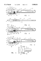
- FIG. 1 is a top view of the improved adjustable box wrench of this invention in an assembled configuration
- FIG. 2 is a side view of the improved adjustable box wrench of this invention in an assembled configuration
- FIG. 4 is a top view of the wrench body with both the closure plate and the movable jaw adjustment arm removed;
- FIG. 5 is a top view of the movable jaw and adjustment arm
- FIG. 6 is an end view of the movable jaw and adjustment arm
- FIG. 7 is a bottom view of the movable jaw and adjustment arm
- FIG. 8 is a side plan view of the adjustment worm screw with holding pin
- FIG. 9 is an end cross-sectional view of the mouth of the wrench along lines A--A of FIG. 3;
- FIG. 10 is a side exploded plan view of the improved adjustable box wrench of this invention.
- the wrench body 1 contains an elongated handle 2 which extends longitudinally from the head of the wrench 3.
- the head of the wrench 3 contains a mouth or cavity 9 which is designed to fit around a nut, bolt or the like.
- the mouth 9 is adjustable in size by moving a movable jaw 5 between two longitudinal gripping surfaces 32 on opposite sides of the mouth 9.
- the slanted gripping surface 31 of the movable jaw, together with the two longitudinal gripping surfaces 32 and the fixed gripping surface 27 on the distal end of the mouth completed or enclosed the head of a nut or bolt or the like on which the wrench is being used.
- the movable jaw 5 is moved longitudinally by means of an adjustment arm 4 that is contained in a cavity 14 between the handle 2 and the head 3 of the wrench.
- the cavity 14 is large enough to accommodate the full movement of the arm 4 so that the movable jaw 5 can move within the entire length of the mouth 9 to fit a wide range of sizes of nuts, bolts and the like.
- the adjustment arm 4 contains angular teeth 20.
- the adjustment means consists of a worm screw 8 as shown in FIG. 8, which is mounted by a holding pin 18 in a cavity 17 adjacent and contiguous with the cavity 14 for the adjustment arm 4.
- the worm screw 8 contains angular turning gear 24 which fit between the teeth 20 and the adjustment arm 4 such that when the worm screw 8 is turned by a user's fingers the adjustment arm 4 in turn moves the movable jaw 5, thereby changing the size of the mouth 9.
- the combination of the worm screw 8 and adjustment arm 4 provides an adjustment means that is precise, accurate and reduces play in the movable jaw 5 when the mouth 9 is around a nut, bolt or the like.
- a longitudinal channel 26 is provided in the longitudinal surfaces 32 on the opposite sides of the mouth 9 into which a protrusion 19 located adjacent a lowermost end on each side of the jaws 21 is inserted and moves within as the size of the mouth 9 is adjusted.
- the proximal gripping surfaces of the movable jaw 5 and the opposing distal gripping surface 27 would be comprised of equal length angular surfaces 31 on the movable jaw 5 and on the distal gripping surface 27. These gripping surfaces would be slanted outward from the center of the mouth to meet at vortices 22 on the movable jaw 5 and 25 on the distal fixed gripping surface, respectively. In this manner the mouth 9 of the wrench could be used on a variety of nuts and bolts ranging from those having four sides or more.
- the wrench may have a removable closure plate 6 covering the cavity with adjustment arm 14 and cavity for the adjustment worm screw 8 to secure the adjustment arm 4 and worm screw 8 in place.
- the closure plate 6 would have removable securing screws 7 which would fit into holes 15 in the wrench body 1.
- the wrench body under the removable closure plate 6 would also have slots 33 at the proximal end of the mouth so that the movable jaw 5 and adjustment arm 4 could be removed by allowing the protrusions 19 on the sides of the jaw 21 to be lifted.
- the movable jaw 5 could also contain sides 21 with pointed ends 23 which fully contact the longitudinal gripping surfaces 32 to provide further lateral support and strength for the wrench.
- FIG. 10 all of the components of the wrench and the manner of assembly are illustrated.
- the holding pin 18 is inserted into the central hole 34 in the worm screw 8 which in turn is placed into the cavity 17 in the wrench body with the front of the pin 18 being placed into a worm screw pin front tip holding cavity 30.
- the adjustment arm 4 and removable jaw 5 are placed into the adjustment arm cavity 14 and mouth 9 so that the gear 24 on the worm screw 8 fit between the slanted teeth 20 on the adjustment arm 4 and the protrusion 19 on the sides 21 of the movable jaw 5 fit into slots 33.
- the final step in the assembly process is to install the closure plate 6 by inserting screws 7 through holes 28 and into threaded holes 15 in the body of the wrench 1.
- head 3 includes a top and a bottom that taper toward each other beginning at the removable closure plate 6. See also FIG. 2.
- this invention provides a new and improved adjustable box wrench with improved adjustment means that reduces play in the adjustable jaw 5 and which reduces slippage of the mouth 9 while used around a nut or bolt.
- Increased lateral support is provided by protrusions 19 which fit into groves 26 in the opposing longitudinal gripping surfaces 32.
- Easy assembly and disassembly is provided by use of a closure plate 6.
Landscapes
- Engineering & Computer Science (AREA)
- Mechanical Engineering (AREA)
- Details Of Spanners, Wrenches, And Screw Drivers And Accessories (AREA)
Abstract
An improved adjustable box wrench having a mouth (9) with a plurality of gripping surfaces (27, 31, 32) for surrounding a nut, bolt or the like. A movable jaw (5) allows the size of the mouth to be altered when a worm screw (8) is turned. The worm screw (8) has gear (24) which fit between teeth (20) in an arm (4) extending from the movable jaw (5). The adjustment arm (4) and worm screw (8) fit into cavities (14, 17) in the wrench body (1). Increased lateral support for the movable jaw is provided by protrusions (19) on each side (21) of the jaw which fit into and move longitudinally within channels (26) in fixed gripping surfaces (32) on opposite sides of the mouth (9). A removable closure plate (6) covers the adjustment arm (4) and the worm screw (8) and facilitates assembly of the wrench and disassembly for repair or other purposes.
Description
This invention relates to tools and more particularly, to an improved wrench which is adjustable to fit completely around any size of nut, bolt or the like.
Conventional adjustable wrenches utilize a pair of jaws which contact only two sides of a nut or a bolt, thereby making the wrench prone to slipping during use. Such wrenches also allow too much play due to the adjustment mechanisms used therein. Slippage during use can cause injury to the user's knuckles or other part of the hands. In an effort to overcome such problems, adjustable wrenches which grip nuts and bolts on all sides, also known as "box wrenches," have been developed. However, current box wrenches often still allow too much play, thereby losing their grip or lock on a nut or bolt during use.
Thus, there exists a need for an improved adjustable box wrench that eliminates play and provides a non-slip grip or lock on bolts and nuts which are not provided by current box wrenches.
The most pertinent prior art includes the following patents:
______________________________________
Patent No.
(U.S. unless stated otherwise)
                  Inventor   Issue Date
______________________________________
390,422           White      Oct. 2, 1888
4,766,786         Jeremic    Aug. 30 1988
Des.239,759       Glantz     May 4, 1976
4,987,805         Ejdenwik   Jan. 29, 1991
Swed.60657                   March 11, 1923
Des.313,925       Cone       Jan. 22, 1991
Des.322,545       Cone       Dec. 24, 1991
3,204,497         Dinkler    Sept. 7, 1965
717,390           Gray       Dec. 30, 1902
Des.303,916       Colvin     Oct. 10, 1989
Des.304,669       Boyd et al.
                             Nov. 21, 1989
4,967,613         Cone       Nov. 6, 1990
______________________________________
The White patent teaches an adjustable box wrench with a gripping jaw which uses a thumb nut on a screw rod as the adjustment mechanism. The Jeremic patent discloses an adjustable wrench with a removable key adjustment mechanism. The Glantz patent shows an adjustable ring spanner for a wrench. The Ejdenwik patent discloses an adjustable wrench with a box end different from the present invention. The Swedish patent shows a wrench with an adjustable box end. The two Cone design patents show adjustable box wrenches with gripping ends. The Dinkler patent teaches a double ended adjustable box wrench. The Gray patent discloses a double-ended adjustable wrench. The Colvin patent shows another double ended adjustable box wrench with a different gripping head than the present invention. The Cone utility patent teaches an adjustable box wrench that requires a large aperture in the jaw slot into which the thumb wheel screw and the threaded adjustment rod must fit. Thus, as designed the adjustment mechanism of the Cone patent allows considerable play in the adjustment mechanism, making it susceptible to slippage during use.
Although the prior art contains many patented box wrenches, none has the same structure as the present invention which provides the benefits of the present invention as is described and illustrated herein.
The major objects of the present invention are to provide an improved adjustable box wrench which:
Provides a better grip on nuts, bolts and the like by eliminating play in the grip;
Is more precise;
Provides more lateral support, thereby even further reducing slippage;
Is stronger than conventional box wrenches;
Is safer than other adjustable box wrenches because it reduces slippage and thereby reduces the likelihood of injury; and
Provides a "lock" on a nut or bolt, thereby reducing the likelihood of slippage.
The present invention fulfills the above and other objects by providing an improved adjustable box wrench having a handle and jaw portion. The jaw portion has a plurality of gripping surfaces which form a closed mouth for placing around bolts, nuts and the like. Two of the gripping surfaces are longitudinally located on opposite sides of the mouth and are fixed. A third gripping surface is fixed and is located at the distal end of the mouth and a fourth gripping surface resides on a movable jaw which is adjustable according to the size of the nut, bolt or the like on which the wrench is used. An adjustment arm is connected to the movable jaw on an opposite side of its gripping surface. The adjustment arm moves longitudinally within a cavity located in the wrench between the mouth and the handle. Means for moving the adjustment arm is also provided in the cavity adjacent to the arm in the wrench. An elongated handle is provided which extends longitudinally from the jaw portion to provide sufficient leverage for turning nuts, bolts and the like. To facilitate assembly and disassembly of the wrench for repair or other purposes, a removable closure plate is provided which covers the adjustment arm and adjustment means. The fixed gripping surface on the distal end and the movable gripping surface on the movable jaw at the proximal end of the mouth, may each have two equal length angular surfaces indented outward from the center of the mouth to provide more lateral support to the gripping surfaces for use on nuts and bolts having more than four sides. For increased strength and to reduce slippage the mouth may contain grooves in the two longitudinal gripping surfaces and the movable jaw may have outward protrusions on its sides which fit into and move within the grooves whenever the size of the mouth is adjusted. The adjustment means use to move the adjustment arm, thereby changing the size of the mouth, is preferably a worm screw with helical gears on its circumference which fit into teeth on the adjustment arm, such that when a worm screw is turned it causes the adjustment arm to move longitudinally within the longitudinal cavity, thereby moving the movable jaw and altering the size of the mouth as desired.
The above and other objects, features and advantages of the present invention should become even more readily apparent to those skilled in the art upon a reading of the following detailed description in conjunction with the drawings wherein there is shown and described illustrative embodiments of the invention.
In the following detailed description, reference will be made to the attached drawings in which:
FIG. 1 is a top view of the improved adjustable box wrench of this invention in an assembled configuration;
FIG. 2 is a side view of the improved adjustable box wrench of this invention in an assembled configuration;
FIG. 3 is a top view the improved adjustable box wrench of this invention with the closure plate removed;
FIG. 4 is a top view of the wrench body with both the closure plate and the movable jaw adjustment arm removed;
FIG. 5 is a top view of the movable jaw and adjustment arm;
FIG. 6 is an end view of the movable jaw and adjustment arm;
FIG. 7 is a bottom view of the movable jaw and adjustment arm;
FIG. 8 is a side plan view of the adjustment worm screw with holding pin;
FIG. 9 is an end cross-sectional view of the mouth of the wrench along lines A--A of FIG. 3; and
FIG. 10 is a side exploded plan view of the improved adjustable box wrench of this invention.
For purposes of describing the preferred embodiment, the terminology used in reference to the numbered components in the drawings is as follows:
______________________________________ 1.wrench body 21. sides of jaw 2.handle 22. movable indent of 3. headadjustable jaw 4.adjustment arm 23. pointed tips of adjustable 5. movable jaw jaw. 6.closure plate 24. wormscrew turning gear 7. securing screws for 25. distal fixed grippingclosure plate surface 8.adjustment worm screw 26. channel forside 9. mouth (cavity)extensions 10. top ofhead 27. fixed distal slanted 11. bottom of head grippingsurface face 12.top slant 28. screw holes inclosure 13.bottom slant plate 14.adjustment arm cavity 29.closure plate cavity 15. holes for plate securing 30. worm screw pin front tip screws (8) holdingcavity 16. holding pin forworm 31. slantedgripping surface screw 32. fixed longitudinal 17. worm screw cavity gripping surfaces 18. slot forworm screw pin 33.removal slot 19.side extensions 34. central hole inworm 20. adjustment arm teeth screw (8) ______________________________________
Referring to FIG. 1, the wrench body 1 contains an elongated handle 2 which extends longitudinally from the head of the wrench 3. The head of the wrench 3 contains a mouth or cavity 9 which is designed to fit around a nut, bolt or the like. The mouth 9 is adjustable in size by moving a movable jaw 5 between two longitudinal gripping surfaces 32 on opposite sides of the mouth 9. The slanted gripping surface 31 of the movable jaw, together with the two longitudinal gripping surfaces 32 and the fixed gripping surface 27 on the distal end of the mouth completed or enclosed the head of a nut or bolt or the like on which the wrench is being used.
As further illustrated in FIGS. 1, 2, 3 and 4, the movable jaw 5 is moved longitudinally by means of an adjustment arm 4 that is contained in a cavity 14 between the handle 2 and the head 3 of the wrench. The cavity 14 is large enough to accommodate the full movement of the arm 4 so that the movable jaw 5 can move within the entire length of the mouth 9 to fit a wide range of sizes of nuts, bolts and the like.
As shown in FIGS. 5, 6 and 7 the adjustment arm 4 contains angular teeth 20. The adjustment means consists of a worm screw 8 as shown in FIG. 8, which is mounted by a holding pin 18 in a cavity 17 adjacent and contiguous with the cavity 14 for the adjustment arm 4. The worm screw 8 contains angular turning gear 24 which fit between the teeth 20 and the adjustment arm 4 such that when the worm screw 8 is turned by a user's fingers the adjustment arm 4 in turn moves the movable jaw 5, thereby changing the size of the mouth 9. The combination of the worm screw 8 and adjustment arm 4 provides an adjustment means that is precise, accurate and reduces play in the movable jaw 5 when the mouth 9 is around a nut, bolt or the like.
To provide further lateral support for the movable jaw 5, as shown in FIG. 9, a longitudinal channel 26 is provided in the longitudinal surfaces 32 on the opposite sides of the mouth 9 into which a protrusion 19 located adjacent a lowermost end on each side of the jaws 21 is inserted and moves within as the size of the mouth 9 is adjusted. The proximal gripping surfaces of the movable jaw 5 and the opposing distal gripping surface 27 would be comprised of equal length angular surfaces 31 on the movable jaw 5 and on the distal gripping surface 27. These gripping surfaces would be slanted outward from the center of the mouth to meet at vortices 22 on the movable jaw 5 and 25 on the distal fixed gripping surface, respectively. In this manner the mouth 9 of the wrench could be used on a variety of nuts and bolts ranging from those having four sides or more.
As shown in FIGS. 1, 2 and 3, to facilitate assembly of the wrench and disassembly for repair or other purposes, the wrench may have a removable closure plate 6 covering the cavity with adjustment arm 14 and cavity for the adjustment worm screw 8 to secure the adjustment arm 4 and worm screw 8 in place. Preferably the closure plate 6 would have removable securing screws 7 which would fit into holes 15 in the wrench body 1. The wrench body under the removable closure plate 6 would also have slots 33 at the proximal end of the mouth so that the movable jaw 5 and adjustment arm 4 could be removed by allowing the protrusions 19 on the sides of the jaw 21 to be lifted. The movable jaw 5 could also contain sides 21 with pointed ends 23 which fully contact the longitudinal gripping surfaces 32 to provide further lateral support and strength for the wrench.
In FIG. 10 all of the components of the wrench and the manner of assembly are illustrated. First, with the wrench body 1 having a head 3 and handle 2 as previously described, the holding pin 18 is inserted into the central hole 34 in the worm screw 8 which in turn is placed into the cavity 17 in the wrench body with the front of the pin 18 being placed into a worm screw pin front tip holding cavity 30. Then the adjustment arm 4 and removable jaw 5 are placed into the adjustment arm cavity 14 and mouth 9 so that the gear 24 on the worm screw 8 fit between the slanted teeth 20 on the adjustment arm 4 and the protrusion 19 on the sides 21 of the movable jaw 5 fit into slots 33. The final step in the assembly process is to install the closure plate 6 by inserting screws 7 through holes 28 and into threaded holes 15 in the body of the wrench 1. In addition, head 3 includes a top and a bottom that taper toward each other beginning at the removable closure plate 6. See also FIG. 2.
It should become readily apparent that as described and illustrated above in relation to the preferred embodiment, this invention provides a new and improved adjustable box wrench with improved adjustment means that reduces play in the adjustable jaw 5 and which reduces slippage of the mouth 9 while used around a nut or bolt. Increased lateral support is provided by protrusions 19 which fit into groves 26 in the opposing longitudinal gripping surfaces 32. Easy assembly and disassembly is provided by use of a closure plate 6.
Although only a few embodiments of the present invention have been described in detail hereinabove, all improvements and modifications to this invention within the scope or equivalents of the claims are covered by this invention.
Claims (10)
1. An adjustable box wrench comprising:
an elongated handle;
a head connected to one end of said elongated handle;
an aperture provided in said head and having a distal end and a proximal end;
a movable jaw including a first gripping surface and sides, said movable jaw being positioned in said aperture for sliding movement between said proximal end and said distal end for allowing said wrench to selectively grip a workpiece;
a protrusion provided on each of said sides of said movable jaw;
an adjustment arm connected to said movable jaw on an opposite side of said first gripping surface;
a gear for cooperating engagement with said adjustment arm for selectively moving said movable jaw;
a second gripping surface provided at a distal end of said aperture in opposing relationship to said first gripping surface;
third and fourth gripping surfaces extending longitudinally between said first and second gripping surfaces, said third gripping surface being in opposing, spaced apart relation to said fourth gripping surface;
a support groove provided in each of said third and said fourth gripping surfaces for mating engagement with a respective said protrusion on said movable jaw to increase lateral support of said movable jaw; and
a removal slot located along each of said support grooves for permitting removal of said protrusions from said support grooves to disassemble and repair said wrench.
2. The adjustable wrench of claim 1, wherein said gear includes a worm screw.
3. The adjustable wrench of claim 1, wherein said head includes a top and a bottom that taper inwardly toward each other.
4. The adjustable wrench of claim 1, wherein said protrusions are located adjacent a lowermost end of said sides.
5. The adjustable wrench of claim 1, further comprising a cavity in said wrench for receiving said adjustment arm and a removable closure plate to cover said cavity.
6. The adjustable wrench of claim 1, wherein said adjustment arm includes teeth on only one side of said adjustment arm.
7. The adjustable wrench of claim 1, wherein said removal slots are located adjacent said proximal end of said cavity.
8. The adjustable wrench of claim 1, wherein said movable jaw and said protrusions are unitary.
9. The adjustable wrench of claim 5, wherein said head includes a top and a bottom that taper inwardly toward each other beginning at said removable closure plate.
10. An adjustable box wrench comprising:
an elongated handle;
a head connected to one end of said elongated handle;
an aperture provided in said head and having a distal end and a proximal end;
a movable jaw including a first gripping surface and sides, said movable jaw being positioned in said aperture for sliding movement between said proximal end and said distal end for allowing said wrench to selectively grip a workpiece;
a protrusion provided on each of said sides of said movable jaw, said protrusions being located adjacent a lowermost end of said sides;
an adjustment arm connected to said movable jaw on an opposite side of said first gripping surface;
a gear for cooperating engagement with said adjustment arm for selectively moving said movable jaw;
a second gripping surface provided at a distal end of said aperture in opposing relationship to said first gripping surface;
third and fourth gripping surfaces extending longitudinally between said first and second gripping surfaces, said third gripping surface being in opposing, spaced apart relation to said fourth gripping surface;
a support groove provided in each of said third and said fourth gripping surfaces for mating engagement with a respective said protrusion on said movable jaw to increase lateral support of said movable jaw; and
a removal slot located along each of said support grooves for permitting removal of said protrusions from said support grooves to disassemble and repair said wrench, said removal slots being located adjacent said proximal end of said cavity;
said head including a top and a bottom that taper inwardly toward each other; and
wherein said wrench further includes a cavity for receiving said adjustment arm and a removable closure plate to cover said cavity.
Priority Applications (4)
| Application Number | Priority Date | Filing Date | Title |
|---|---|---|---|
| US08/785,655 US5988024A (en) | 1997-01-17 | 1997-01-17 | Adjustable box wrench |
| PCT/US1997/020339 WO1998031508A1 (en) | 1997-01-17 | 1997-11-04 | Improved adjustable box wrench |
| AU52496/98A AU5249698A (en) | 1997-01-17 | 1997-11-04 | Improved adjustable box wrench |
| US09/444,681 US6240814B1 (en) | 1997-01-17 | 1999-11-22 | Adjustable box wrench |
Applications Claiming Priority (1)
| Application Number | Priority Date | Filing Date | Title |
|---|---|---|---|
| US08/785,655 US5988024A (en) | 1997-01-17 | 1997-01-17 | Adjustable box wrench |
Related Child Applications (1)
| Application Number | Title | Priority Date | Filing Date |
|---|---|---|---|
| US09/444,681 Continuation-In-Part US6240814B1 (en) | 1997-01-17 | 1999-11-22 | Adjustable box wrench |
Publications (1)
| Publication Number | Publication Date |
|---|---|
| US5988024A true US5988024A (en) | 1999-11-23 |
Family
ID=25136207
Family Applications (2)
| Application Number | Title | Priority Date | Filing Date |
|---|---|---|---|
| US08/785,655 Expired - Fee Related US5988024A (en) | 1997-01-17 | 1997-01-17 | Adjustable box wrench |
| US09/444,681 Expired - Fee Related US6240814B1 (en) | 1997-01-17 | 1999-11-22 | Adjustable box wrench |
Family Applications After (1)
| Application Number | Title | Priority Date | Filing Date |
|---|---|---|---|
| US09/444,681 Expired - Fee Related US6240814B1 (en) | 1997-01-17 | 1999-11-22 | Adjustable box wrench |
Country Status (3)
| Country | Link |
|---|---|
| US (2) | US5988024A (en) |
| AU (1) | AU5249698A (en) |
| WO (1) | WO1998031508A1 (en) |
Cited By (8)
| Publication number | Priority date | Publication date | Assignee | Title |
|---|---|---|---|---|
| US6240814B1 (en) | 1997-01-17 | 2001-06-05 | Bill E. Boyd | Adjustable box wrench |
| CN102501212A (en) * | 2011-11-17 | 2012-06-20 | 尚玉东 | Combined type metering quincuncial plate |
| TWI496664B (en) * | 2013-09-11 | 2015-08-21 | Jun Fan Chen | Adjustable wrench |
| US20170320195A1 (en) * | 2016-05-09 | 2017-11-09 | Southern Handling and Delivery, LLC | Adjustable wrench |
| US20180021928A1 (en) * | 2016-05-09 | 2018-01-25 | Southern Handling and Delivery, LLC | Adjustable wrench |
| US10350736B2 (en) | 2013-06-21 | 2019-07-16 | Stanley Black & Decker Mea Fze | Slogging wrench |
| CN113339434A (en) * | 2021-05-24 | 2021-09-03 | 宁波划一马达有限公司 | Shaft lock |
| USD1018229S1 (en) * | 2021-10-18 | 2024-03-19 | William L. Hobson, Jr. | Battery powered wrench |
Families Citing this family (23)
| Publication number | Priority date | Publication date | Assignee | Title |
|---|---|---|---|---|
| US6545384B1 (en) * | 1997-02-07 | 2003-04-08 | Sri International | Electroactive polymer devices |
| TW512765U (en) * | 2001-12-31 | 2002-12-01 | Shiou-Ching Huang | Adjustable wrench allowing reciprocal operation |
| GB2388806B (en) * | 2002-05-21 | 2006-01-25 | Victor Martin Goddard | Tool |
| US20050022631A1 (en) * | 2002-12-20 | 2005-02-03 | Brazil Bill Thomas | Non-marring tool |
| EP2174360A4 (en) | 2007-06-29 | 2013-12-11 | Artificial Muscle Inc | Electroactive polymer transducers for sensory feedback applications |
| EP2239793A1 (en) | 2009-04-11 | 2010-10-13 | Bayer MaterialScience AG | Electrically switchable polymer film structure and use thereof |
| US20120000319A1 (en) * | 2010-02-09 | 2012-01-05 | Titan Technologies International, Inc. | Backup Tool for Holding Nuts |
| WO2012118916A2 (en) | 2011-03-01 | 2012-09-07 | Bayer Materialscience Ag | Automated manufacturing processes for producing deformable polymer devices and films |
| CN103703404A (en) | 2011-03-22 | 2014-04-02 | 拜耳知识产权有限责任公司 | Electroactive polymer actuator lenticular system |
| EP2828901B1 (en) | 2012-03-21 | 2017-01-04 | Parker Hannifin Corporation | Roll-to-roll manufacturing processes for producing self-healing electroactive polymer devices |
| US9761790B2 (en) | 2012-06-18 | 2017-09-12 | Parker-Hannifin Corporation | Stretch frame for stretching process |
| US9590193B2 (en) | 2012-10-24 | 2017-03-07 | Parker-Hannifin Corporation | Polymer diode |
| US9743726B1 (en) | 2013-05-19 | 2017-08-29 | John F. Belock | Advanced adjustable finger ring apparatus and methods |
| USD718996S1 (en) * | 2014-04-07 | 2014-12-09 | Ibt Holding Llc | Wrench |
| USD718995S1 (en) * | 2014-04-07 | 2014-12-09 | Ibt Holdings, Llc | Wrench |
| US9469018B2 (en) * | 2014-06-26 | 2016-10-18 | Toolrieh Imp & Exp. Co., Ltd. | Adjustable wrench |
| CN106392964B (en) * | 2016-11-11 | 2018-05-08 | 盐城市新澳精密锻造有限公司 | Bore adjustable spanner |
| CN106392977B (en) * | 2016-11-11 | 2018-05-15 | 台州市点睛模业有限公司 | With the electric adjustable wrench twisted |
| CN106346399B (en) * | 2016-11-11 | 2018-05-08 | 东台市润生纺机专件有限公司 | The novel adjustable spanner adjusted easy to bore |
| CN106392963B (en) * | 2016-11-11 | 2018-07-10 | 江苏科力斯通新材料有限公司 | The electric wrench adjusted convenient for bore |
| CN106378739B (en) * | 2016-11-11 | 2018-07-10 | 江苏科力斯通新材料有限公司 | The Novel electric wrench adjusted convenient for bore |
| CN106392961B (en) * | 2016-11-11 | 2018-05-08 | 苏州创必成电子科技有限公司 | The monkey wrench adjusted easy to bore |
| CN109093564B (en) * | 2018-09-29 | 2021-02-09 | 宁波鄞州竹创信息科技有限公司 | Nut dismounting tool for metallurgical mechanical equipment |
Citations (13)
| Publication number | Priority date | Publication date | Assignee | Title |
|---|---|---|---|---|
| US390422A (en) * | 1888-10-02 | Wrench | ||
| US717390A (en) * | 1902-05-19 | 1902-12-30 | Adelbert S Gray | Nut-wrench. |
| US1133132A (en) * | 1914-12-19 | 1915-03-23 | John W Greb | Wrench. |
| US1359403A (en) * | 1920-02-21 | 1920-11-16 | Jesse H Lynds | Wrench |
| US3204497A (en) * | 1964-02-07 | 1965-09-07 | Technical Entpr Inc | Simultaneously adjustable doubleended wrench |
| US4520699A (en) * | 1983-05-02 | 1985-06-04 | Miodrag Jeremic | Adjustable wrench |
| US4766786A (en) * | 1987-01-14 | 1988-08-30 | Miodrag Jeremic | Adjustable wrench |
| USD303916S (en) | 1987-03-24 | 1989-10-10 | Davis S. Colvin | Double-ended box wrench |
| USD304669S (en) | 1987-03-13 | 1989-11-21 | Boyd William D | Adjustable wrench |
| US4967613A (en) * | 1989-07-11 | 1990-11-06 | Sde Investments, Inc. | Reversible adjustable wrench |
| USD313925S (en) | 1988-06-06 | 1991-01-22 | SPE Investments, Inc. | Reversable adjustable wrench |
| US4987805A (en) * | 1987-12-02 | 1991-01-29 | Noren & Persson Ab | Adjustable eyebolt key |
| USD322545S (en) | 1989-08-14 | 1991-12-24 | SDE Investments, Inc. (Corp. of Michigan) | Adjustable wrench |
Family Cites Families (5)
| Publication number | Priority date | Publication date | Assignee | Title |
|---|---|---|---|---|
| US4838132A (en) * | 1982-03-11 | 1989-06-13 | Donald Pyles | Adjustable wrench |
| USD304699S (en) | 1987-07-16 | 1989-11-21 | De Brey Robert J | Lapel button |
| USD322542S (en) | 1989-05-09 | 1991-12-24 | Enrique Bernat F., S.A. | Combined display and dispenser for lollipops |
| US5988024A (en) | 1997-01-17 | 1999-11-23 | Boyd; Bill E. | Adjustable box wrench |
| USD390764S (en) | 1997-01-17 | 1998-02-17 | Boyd Bill E | Adjustable box wrench |
-
1997
- 1997-01-17 US US08/785,655 patent/US5988024A/en not_active Expired - Fee Related
- 1997-11-04 AU AU52496/98A patent/AU5249698A/en not_active Abandoned
- 1997-11-04 WO PCT/US1997/020339 patent/WO1998031508A1/en not_active Ceased
-
1999
- 1999-11-22 US US09/444,681 patent/US6240814B1/en not_active Expired - Fee Related
Patent Citations (13)
| Publication number | Priority date | Publication date | Assignee | Title |
|---|---|---|---|---|
| US390422A (en) * | 1888-10-02 | Wrench | ||
| US717390A (en) * | 1902-05-19 | 1902-12-30 | Adelbert S Gray | Nut-wrench. |
| US1133132A (en) * | 1914-12-19 | 1915-03-23 | John W Greb | Wrench. |
| US1359403A (en) * | 1920-02-21 | 1920-11-16 | Jesse H Lynds | Wrench |
| US3204497A (en) * | 1964-02-07 | 1965-09-07 | Technical Entpr Inc | Simultaneously adjustable doubleended wrench |
| US4520699A (en) * | 1983-05-02 | 1985-06-04 | Miodrag Jeremic | Adjustable wrench |
| US4766786A (en) * | 1987-01-14 | 1988-08-30 | Miodrag Jeremic | Adjustable wrench |
| USD304669S (en) | 1987-03-13 | 1989-11-21 | Boyd William D | Adjustable wrench |
| USD303916S (en) | 1987-03-24 | 1989-10-10 | Davis S. Colvin | Double-ended box wrench |
| US4987805A (en) * | 1987-12-02 | 1991-01-29 | Noren & Persson Ab | Adjustable eyebolt key |
| USD313925S (en) | 1988-06-06 | 1991-01-22 | SPE Investments, Inc. | Reversable adjustable wrench |
| US4967613A (en) * | 1989-07-11 | 1990-11-06 | Sde Investments, Inc. | Reversible adjustable wrench |
| USD322545S (en) | 1989-08-14 | 1991-12-24 | SDE Investments, Inc. (Corp. of Michigan) | Adjustable wrench |
Cited By (12)
| Publication number | Priority date | Publication date | Assignee | Title |
|---|---|---|---|---|
| US6240814B1 (en) | 1997-01-17 | 2001-06-05 | Bill E. Boyd | Adjustable box wrench |
| CN102501212A (en) * | 2011-11-17 | 2012-06-20 | 尚玉东 | Combined type metering quincuncial plate |
| US10350736B2 (en) | 2013-06-21 | 2019-07-16 | Stanley Black & Decker Mea Fze | Slogging wrench |
| TWI496664B (en) * | 2013-09-11 | 2015-08-21 | Jun Fan Chen | Adjustable wrench |
| US20170320195A1 (en) * | 2016-05-09 | 2017-11-09 | Southern Handling and Delivery, LLC | Adjustable wrench |
| US9833882B2 (en) * | 2016-05-09 | 2017-12-05 | Southern Handling and Delivery, LLC | Adjustable wrench |
| US20180021928A1 (en) * | 2016-05-09 | 2018-01-25 | Southern Handling and Delivery, LLC | Adjustable wrench |
| US10786889B2 (en) * | 2016-05-09 | 2020-09-29 | Southern Handling and Delivery, LLC | Adjustable wrench |
| US11707820B2 (en) | 2016-05-09 | 2023-07-25 | Southern Handling and Delivery, LLC | Adjustable wrench |
| CN113339434A (en) * | 2021-05-24 | 2021-09-03 | 宁波划一马达有限公司 | Shaft lock |
| CN113339434B (en) * | 2021-05-24 | 2025-03-21 | 宁波划一马达有限公司 | A shaft lock |
| USD1018229S1 (en) * | 2021-10-18 | 2024-03-19 | William L. Hobson, Jr. | Battery powered wrench |
Also Published As
| Publication number | Publication date |
|---|---|
| WO1998031508A1 (en) | 1998-07-23 |
| US6240814B1 (en) | 2001-06-05 |
| AU5249698A (en) | 1998-08-07 |
Similar Documents
| Publication | Publication Date | Title |
|---|---|---|
| US5988024A (en) | Adjustable box wrench | |
| US4542667A (en) | Tool handle | |
| US5520075A (en) | Socket wrench set and fastener | |
| US4967613A (en) | Reversible adjustable wrench | |
| US5582083A (en) | Open end wrench with removable handle | |
| US3672419A (en) | Hand tools | |
| US5131312A (en) | Surface conforming, torque enhancing wrench | |
| US6145417A (en) | Convertible plier tool | |
| US3283621A (en) | Socket wrenches | |
| US4787275A (en) | Adjustable double-ended box wrench | |
| CA2242131A1 (en) | Movable grip for double-ended wrench | |
| US4970917A (en) | Stud extractor and wrench apparatus | |
| JPS6318605U (en) | ||
| US4867018A (en) | Phillips screwdriver with retractable slotted screwdriver blade | |
| US3306142A (en) | Open end slideable jaw wrench | |
| US4766786A (en) | Adjustable wrench | |
| US4955262A (en) | Socket pipe wrench | |
| US2753746A (en) | Fastener-holding socket wrench | |
| US4920834A (en) | Socket pipe wrench | |
| US20030115991A1 (en) | Torque transfer mechanism for socket wrench | |
| US3253486A (en) | Wrench having sliding side jaws adjustable by means of a bar having right and left threads | |
| US4698993A (en) | Riveting tool for one side riveting of rivet nuts | |
| US20030015069A1 (en) | Hand tool angle adjustment structure | |
| US5606896A (en) | Articulated gripping box wrench for tight spaces | |
| US7942082B1 (en) | Crankable hand wrench |
Legal Events
| Date | Code | Title | Description |
|---|---|---|---|
| FPAY | Fee payment |
Year of fee payment: 4 |
|
| REMI | Maintenance fee reminder mailed | ||
| LAPS | Lapse for failure to pay maintenance fees | ||
| STCH | Information on status: patent discontinuation |
Free format text: PATENT EXPIRED DUE TO NONPAYMENT OF MAINTENANCE FEES UNDER 37 CFR 1.362 |
|
| FP | Lapsed due to failure to pay maintenance fee |
Effective date: 20071123 |