US5984584A - Fairings for drilling riser control pod hoses - Google Patents
Fairings for drilling riser control pod hoses Download PDFInfo
- Publication number
- US5984584A US5984584A US08/853,727 US85372797A US5984584A US 5984584 A US5984584 A US 5984584A US 85372797 A US85372797 A US 85372797A US 5984584 A US5984584 A US 5984584A
- Authority
- US
- United States
- Prior art keywords
- fairing
- elements
- bundled
- surface elements
- thrust bearing
- Prior art date
- Legal status (The legal status is an assumption and is not a legal conclusion. Google has not performed a legal analysis and makes no representation as to the accuracy of the status listed.)
- Expired - Fee Related
Links
Images


Classifications
-
- E—FIXED CONSTRUCTIONS
- E21—EARTH OR ROCK DRILLING; MINING
- E21B—EARTH OR ROCK DRILLING; OBTAINING OIL, GAS, WATER, SOLUBLE OR MELTABLE MATERIALS OR A SLURRY OF MINERALS FROM WELLS
- E21B17/00—Drilling rods or pipes; Flexible drill strings; Kellies; Drill collars; Sucker rods; Cables; Casings; Tubings
- E21B17/01—Risers
Definitions
- the present invention relates to deepwater drilling and production operations. More particularly, the present invention relates to providing protection from vortex induced vibration ("VIV") to parallel runs of intermittently connected cylindrical elements such as drilling riser control pod hoses bundled with wirelines.
- VIV vortex induced vibration
- Assemblies of multiple cylindrical elements or lines such as these hoses and associated wirelines run from surface facilities to valve control pods which manage blow out preventors or "BOPs" on the ocean floor.
- the wireline provides support in deploying, maintaining, and retrieving the control pod hose and clamps interconnect the control pod hose to the wireline at regular intervals along their lengths.
- the control pod hose itself is a multiplex hose in which many hydraulic and/or electrical control lines are bundled within a single sheath. These control lines manipulate valves in the control pod of the BOP or otherwise control remote, subsea equipment.
- Helical strakes and the like may be effective to reduce the VIV, but markedly increase current-induced drag.
- the bundled control pod hoses may be induced to "sail" past the risers and create tangling problems during rulnning and retrieval operations.
- fairings are effective to control both VIV and drag problems.
- fairings such as deployed for VIV protection about single cylindrical elements are not suitable for such tandem or other multiple line assemblies.
- An advantage of the fairing of the present invention is that it is suitable for deployment about bundled, i.e., side by side cylinders. Another advantage of the present invention is the ease of fairing installation about the cylinders.
- the present invention is a fairing system for protecting multiple, parallel, bundled but separate, side-by-side cylindrical elements deployed in offshore applications.
- the fairing system deploys a plurality of elongated fairing surface elements foldable about an axis with a connection system joining the elongated edges of the fairing surface elements in a folded manner about the axis.
- a plurality of thrust bearings are orthogonally connected across the fairing surface elements at each axial end and an axially extending circular rotational surface is defined by the interior of each of the folded fairing surface elements and a transverse edge of the thrust bearings connected thereto. This rotational surface has a diameter which circumscribes the multiple bundled cylindrical elements.
- a plurality of clamps interconnect the multiple bundled, cylindrical elements and a bearing collar on the axial ends of the clamps is provided to receive the thrust bearings of the axial ends of the fairing surface elements.
- FIG. 1 is a side elevational view of a fairing in accordance with the present invention
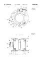
- FIG. 2 is a cross sectional view of the fairing of FIG. 1, taken at line 2--2 in FIG. 1;
- FIG. 3 is a top elevational view of the fairing of FIG. 2 in an open position during deployment about the control pod hose and support line;
- FIG. 4 is a side elevational close-up view of the bottom of the fairing of FIG. 1;
- FIG. 5 is a top elevational, partially broken away view of a clamp for connecting the control pod hose to the support line;
- FIG. 6 is a cross sectional view of the control pod hose and messenger line of FIG. 1, taken at line 6--6 in FIG. 1;
- FIG. 7 is a side elevational view of a clamp for connecting the control pod hose to the messenger line.
- FIG. 8 is a cross sectional view of the control pod hose and support line of FIG. 1, taken at line 8--8 in FIG. 1;
- FIG. 1 illustrates a fairing system 10 for protecting multiple, parallel, bundled but separate, side-by-side cylindrical elements in accordance with the present invention.
- this embodiment deploys the multiple, parallel, bundled but separate, side-by-side cylindrical elements in the form of a riser control pod hose 12 and a wireline 14.
- the riser control pod hose carries a plurality of hydraulic and/or electrical lines 16 (see FIG. 8) within a single sheath 18 for operating a BOP at the sea floor (not shown) during deepwater drilling operations.
- control line/flowline control line/guideline or support line
- control line/guideline control line/guideline or support line
- other offshore applications using two or more cylindrical elements which are adjacent, run parallel and are intermittently connected.
- the illustrated riser control pod hose application connects hose 12 to wireline or support line 14 at regular intervals through a plurality of clamps, here subsea umbilical clamps 20.
- Elongated fairing surface elements 22 are disposed between clamps 20.
- the fairing surface elements wrap or fold around the axis of the tandem cylindrical elements, here the drilling riser control pod hose/wireline assembly 24.
- the fairing surface element is formed from an elongated, rectangular sheet of resilient plastic or nylon and the sheet is elastically deformed into this shape.
- a hinged embodiment could be deployed from a more rigid material.
- the elongated edges of fairing surface elements 22 are joined into a VIV preventing fairing shape through a connection system 26.
- FIGS. 2 and 3 illustrate an embodiment of connection system 26 in greater detail.
- important elements of the connection system are formed integrally with thrust bearings or thrust bearing assembly 28 at the top and bottom of fairing surface elements 22.
- the thrust bearing is formed of first and second elements 30, 32 connected to opposing sides of the fairing surface element as it will fold into position. These first and second elements are attached to the top and bottom ends of the fairing surface element with pins or dowels 38.
- a latch pin 34 is mounted on the first element and a corresponding latch pin receptacle 36 is provided on the second element.
- the latch pin receptacle is provided a recess 40 and the latch pin itself is provided a spring loaded detent finger 42 arranged such that the detent finger will selectively engage the recess 40 to releasably secure the latch pin within the latch pin receptacle and hold the first and second elements of thrust bearing 28 together. It may also be useful to provide an alignment pin 44 and receptacle 46 across this interface.
- the trailing edge of the fairing presents a tail 48. See also FIGS. 1 and 4.
- This tail can be conveniently secured with clips 50 snapping into aligned perforations 52 along the edge of the tail.
- Clips 50 are formed from a resilient material which spring biases finger 56 into the perforations 52.
- a guide 58 at the throat of the clip aids clip installation.
- FIGS. 5-7 provide detailed illustrations of one embodiment for Clamp 20.
- the clamp is a double clam-shell for hinged placement to secure the riser control pod hose/wireline connection.
- Main section 60 attaches about hose 12 and is secured with pivotally retained wing nut assembly 62. It may also be useful to line main section 60 with a non-slip, protective liner 64, here held in place with set screw 66.
- An auxiliary section 68 of clamp 20 is attached to main section 60 and attaches about the wireline. Here it is secured through bolt 70.
- Bearing collar 72 has been largely broken away from FIG. 5 to best illustrate these members.
- Bearing collars 72 are placed on the top and bottom of clamp 20. These are best illustrated in FIGS. 6 which shows the bearing surface 74 and in FIG. 7 which illustrates attachment through flanges 78 and bolts 80. Bearing collars 72 of clamps 20 interface with the thrust bearings 28 on the fairings.
- Thrust bearings 28 also provide an inner partially circumferential surface which, with the inside of the fairing surface element, define a substantially circular rotational surface with a diameter sufficient to circumscribe the bundled cylindrical elements.
- the rotational surfaces about the inside of the fairing and the interfacing bearing surfaces between fairings and between fairings and clamps allow the fairings to rotate freely to orient with the current.
- Embodiments of the present invention can facilitate installation and retrieval and provide a very simple design in which the end pieces efficiently serve to act as 1) fairing closures, 2) radial bearings, and 3) thrust bearings.
Landscapes
- Engineering & Computer Science (AREA)
- Life Sciences & Earth Sciences (AREA)
- Geology (AREA)
- Mining & Mineral Resources (AREA)
- Mechanical Engineering (AREA)
- Physics & Mathematics (AREA)
- Environmental & Geological Engineering (AREA)
- Fluid Mechanics (AREA)
- General Life Sciences & Earth Sciences (AREA)
- Geochemistry & Mineralogy (AREA)
- Earth Drilling (AREA)
Abstract
A fairing system is disclosed for protecting multiple, parallel, bundled but separate cylindrical elements deployed in offshore applications. The fairing system deploys a plurality of elongated fairing surface elements foldable about an axis with a connection system joining the elongated edges of the fairing surface elements in a folded manner about the axis. A plurality of thrust bearings are orthogonally connected across the fairing surface elements at each axial end and an axially extending circular rotational surface is defined by the interior of each of the folded fairing surface elements and a transverse edge of the thrust bearings connected thereto. This rotational surface has a diameter which circumscribes the multiple bundled cylindrical elements. A plurality of clamps interconnect the bundled, cylindrical elements and a bearing collar on the axial ends of the clamps is provided to receive the thrust bearings of the axial ends of the fairing elements.
Description
This application claims benefit of provisional application 60/017,263 filed May 10, 1996.
The present invention relates to deepwater drilling and production operations. More particularly, the present invention relates to providing protection from vortex induced vibration ("VIV") to parallel runs of intermittently connected cylindrical elements such as drilling riser control pod hoses bundled with wirelines.
Assemblies of multiple cylindrical elements or lines such as these hoses and associated wirelines run from surface facilities to valve control pods which manage blow out preventors or "BOPs" on the ocean floor. The wireline provides support in deploying, maintaining, and retrieving the control pod hose and clamps interconnect the control pod hose to the wireline at regular intervals along their lengths. The control pod hose itself is a multiplex hose in which many hydraulic and/or electrical control lines are bundled within a single sheath. These control lines manipulate valves in the control pod of the BOP or otherwise control remote, subsea equipment.
Such applications require long runs which are subject to ocean currents. These currents can cause vortexes to shed from the sides of both the hose and the wireline, thereby inducing vibrations that can lead to the failure of either element or the clamps therebetween. Thus there is a need to provide protection from VIV in the control pod/support line assembly.
Helical strakes and the like, e.g., spiral wrapping ropes around the bundle, may be effective to reduce the VIV, but markedly increase current-induced drag. As a consequence, the bundled control pod hoses may be induced to "sail" past the risers and create tangling problems during rulnning and retrieval operations.
By contrast, fairings are effective to control both VIV and drag problems. However, the practice of using fairings such as deployed for VIV protection about single cylindrical elements are not suitable for such tandem or other multiple line assemblies.
An advantage of the fairing of the present invention is that it is suitable for deployment about bundled, i.e., side by side cylinders. Another advantage of the present invention is the ease of fairing installation about the cylinders.
Towards the fulfillment of the foregoing and other advantages, the present invention is a fairing system for protecting multiple, parallel, bundled but separate, side-by-side cylindrical elements deployed in offshore applications. The fairing system deploys a plurality of elongated fairing surface elements foldable about an axis with a connection system joining the elongated edges of the fairing surface elements in a folded manner about the axis. A plurality of thrust bearings are orthogonally connected across the fairing surface elements at each axial end and an axially extending circular rotational surface is defined by the interior of each of the folded fairing surface elements and a transverse edge of the thrust bearings connected thereto. This rotational surface has a diameter which circumscribes the multiple bundled cylindrical elements. A plurality of clamps interconnect the multiple bundled, cylindrical elements and a bearing collar on the axial ends of the clamps is provided to receive the thrust bearings of the axial ends of the fairing surface elements.
The brief description above, as well as further objects and advantages of the present invention, will be more filly appreciated by reference to the following detailed description of the preferred embodiments which should be read in conjunction with the accompanying drawings in which:
FIG. 1 is a side elevational view of a fairing in accordance with the present invention;
FIG. 2 is a cross sectional view of the fairing of FIG. 1, taken at line 2--2 in FIG. 1;
FIG. 3 is a top elevational view of the fairing of FIG. 2 in an open position during deployment about the control pod hose and support line;
FIG. 4 is a side elevational close-up view of the bottom of the fairing of FIG. 1;
FIG. 5 is a top elevational, partially broken away view of a clamp for connecting the control pod hose to the support line;
FIG. 6 is a cross sectional view of the control pod hose and messenger line of FIG. 1, taken at line 6--6 in FIG. 1;
FIG. 7 is a side elevational view of a clamp for connecting the control pod hose to the messenger line; and
FIG. 8 is a cross sectional view of the control pod hose and support line of FIG. 1, taken at line 8--8 in FIG. 1;
FIG. 1 illustrates a fairing system 10 for protecting multiple, parallel, bundled but separate, side-by-side cylindrical elements in accordance with the present invention. For the purposes of illustration, this embodiment deploys the multiple, parallel, bundled but separate, side-by-side cylindrical elements in the form of a riser control pod hose 12 and a wireline 14. The riser control pod hose carries a plurality of hydraulic and/or electrical lines 16 (see FIG. 8) within a single sheath 18 for operating a BOP at the sea floor (not shown) during deepwater drilling operations. However, the invention is not limited to the illustrated embodiment and those skilled in the art could apply the present invention across a number of control line/flowline, control line/guideline or support line, or other offshore applications using two or more cylindrical elements which are adjacent, run parallel and are intermittently connected.
Returning to FIG. 1, the illustrated riser control pod hose application connects hose 12 to wireline or support line 14 at regular intervals through a plurality of clamps, here subsea umbilical clamps 20. Elongated fairing surface elements 22 are disposed between clamps 20. The fairing surface elements wrap or fold around the axis of the tandem cylindrical elements, here the drilling riser control pod hose/wireline assembly 24. In the illustration, the fairing surface element is formed from an elongated, rectangular sheet of resilient plastic or nylon and the sheet is elastically deformed into this shape. Alternatively, a hinged embodiment could be deployed from a more rigid material. The elongated edges of fairing surface elements 22 are joined into a VIV preventing fairing shape through a connection system 26.
FIGS. 2 and 3 illustrate an embodiment of connection system 26 in greater detail. In this embodiment, important elements of the connection system are formed integrally with thrust bearings or thrust bearing assembly 28 at the top and bottom of fairing surface elements 22. The thrust bearing is formed of first and second elements 30, 32 connected to opposing sides of the fairing surface element as it will fold into position. These first and second elements are attached to the top and bottom ends of the fairing surface element with pins or dowels 38. A latch pin 34 is mounted on the first element and a corresponding latch pin receptacle 36 is provided on the second element. The latch pin receptacle is provided a recess 40 and the latch pin itself is provided a spring loaded detent finger 42 arranged such that the detent finger will selectively engage the recess 40 to releasably secure the latch pin within the latch pin receptacle and hold the first and second elements of thrust bearing 28 together. It may also be useful to provide an alignment pin 44 and receptacle 46 across this interface.
In the illustrated embodiment the trailing edge of the fairing presents a tail 48. See also FIGS. 1 and 4. This tail can be conveniently secured with clips 50 snapping into aligned perforations 52 along the edge of the tail. Clips 50 are formed from a resilient material which spring biases finger 56 into the perforations 52. A guide 58 at the throat of the clip aids clip installation.
FIGS. 5-7 provide detailed illustrations of one embodiment for Clamp 20. Here the clamp is a double clam-shell for hinged placement to secure the riser control pod hose/wireline connection. Main section 60 attaches about hose 12 and is secured with pivotally retained wing nut assembly 62. It may also be useful to line main section 60 with a non-slip, protective liner 64, here held in place with set screw 66. An auxiliary section 68 of clamp 20 is attached to main section 60 and attaches about the wireline. Here it is secured through bolt 70. Bearing collar 72 has been largely broken away from FIG. 5 to best illustrate these members.
The rotational surfaces about the inside of the fairing and the interfacing bearing surfaces between fairings and between fairings and clamps allow the fairings to rotate freely to orient with the current.
Embodiments of the present invention can facilitate installation and retrieval and provide a very simple design in which the end pieces efficiently serve to act as 1) fairing closures, 2) radial bearings, and 3) thrust bearings.
Other modifications, changes, and substitutions are also intended in the forgoing disclosure. Further, in some instances, some features of the present invention will be employed without a corresponding use of other features described in these illustrative embodiments. Accordingly, it is appropriate that the appended claims be construed broadly and in a manner consistent with the spirit and scope of the invention herein.
Claims (11)
1. A fairing system for protecting multiple, parallel, bundled, cylindrical elements deployed in offshore applications, said fairing system comprising:
a plurality of elongated fairing surface elements foldable about an axis and having elongated edges;
a connection system joining the elongated edges of the fairing surface elements in a folded manner about the axis;
a plurality of thrust bearing assemblies at orthogonally connected across each axial end of the fairing surface elements;
an axially extending circular rotational surface defined by the interior of each of the folded fairing surface elements and a transverse edge of the thrust bearing assemblies connected thereto, said rotational surface having a diameter which circumscribes the bundled cylindrical elements;
a plurality of clamps interconnecting the bundled, cylindrical elements; and
a bearing collar on the axial ends of the clamps.
2. A fairing system in accordance with claim 1 wherein the multiple, parallel, bundled cylindrical elements are a tandem set.
3. A fairing system in accordance with claim 2 wherein the tandem set of cylindrical elements comprises a wireline and a drilling riser control pod hose.
4. A fairing system in accordance with claim 1 wherein the elongated fairing surface elements are formed from sheets of resilient plastic.
5. A fairing system in accordance with claim 4 wherein the thrust bearing assemblies connected orthogonally across each axial end of the fairing surface elements comprises:
a first element connected to the fairing surface element;
a second element connected to the fairing surface element;
a bearing surface; and
wherein the connection system joining the elongated edges of the fairing surface elements comprises:
a latch pin carried on the first element of the thrust bearing;
a latch pin receiving receptacle on the second element of the thrust bearing;
a locking recess in the latch pin receiving receptacle; and
a detent finger projecting from the latch pin transverse to its axial reception within the latch pin receiving receptacle and selectively engagable within the locking recess.
6. A fairing system in accordance with claim 5 wherein the connection system joining the elongated edges of the fairing surface elements further comprises:
a guide pin carried on the first element;
a corresponding guide pin receptacle in the second element.
7. A fairing system in accordance with claim 6 wherein the connection system joining the elongated edges of the fairing surface elements further comprises:
a plurality of tail clips.
8. A fairing system for protecting tandem, bundled, cylindrical elements deployed in offshore applications, said fairing system comprising:
a plurality of elongated fairing surface elements foldable about an axis and having elongated edges;
a connection system joining the elongated edges of the fairing surface elements in a folded manner about the axis;
a plurality of thrust bearing assemblies connected orthogonally across each axial end of the fairing surface elements;
an axially extending circular rotational surface defined by the interior of each of the fairing folded fairing surface elements and a transverse edge of the thrust bearing assemblies connected thereto, said rotational surface having a diameter which circumscribes the tandem, bundled cylindrical elements;
a plurality of clamps interconnecting the bundled, cylindrical elements; and
a bearing collar on the axial ends of the clamps.
9. A fairing system for protecting multiple, parallel, bundled, cylindrical elements deployed in offshore applications, said fairing system comprising:
a plurality of elongated fairing surface elements formed from sheets of resilient plastic foldable about an axis;
a plurality of thrust bearing assemblies connected orthogonally across each axial end of the fairing surface elements, comprising:
a first element connected to the fairing surface element;
a second element connected to the fairing surface element;
a bearing surface;
a connection system joining the elongated edges of the fairing surface elements in a folded manner about the axis, comprising:
a latch pin carried on the first element of the thrust bearing assembly;
a latch pin receiving receptacle on the second element of the thrust bearing;
a locking recess in the latch pin receiving receptacle; and
a detent finger projecting from the latch pin transverse to its axial reception within the latch pin receiving receptacle and selectively engagable within the locking recess;
an axially extending circular rotational surface defined by the interior of each of the folded fairing surface elements and a transverse edge of the thrust bearing assemblies connected thereto, said rotational surface having a diameter which circumscribes the bundled cylindrical elements;
a plurality of clamps interconnecting the bundled, cylindrical elements; and
a bearing collar on the axial ends of the clamps.
10. A fairing system in accordance with claim 9 wherein the connection system joining the elongated edges of the fairing surface elements further comprises:
a guide pin carried on the first element; and
a corresponding guide pin receptacle in the second element.
11. A fairing system in accordance with claim 10 wherein the connection system joining the elongated edges of the fairing surface elements further comprises:
a plurality of tail clips.
Priority Applications (1)
| Application Number | Priority Date | Filing Date | Title |
|---|---|---|---|
| US08/853,727 US5984584A (en) | 1996-05-10 | 1997-05-09 | Fairings for drilling riser control pod hoses |
Applications Claiming Priority (2)
| Application Number | Priority Date | Filing Date | Title |
|---|---|---|---|
| US1726396P | 1996-05-10 | 1996-05-10 | |
| US08/853,727 US5984584A (en) | 1996-05-10 | 1997-05-09 | Fairings for drilling riser control pod hoses |
Publications (1)
| Publication Number | Publication Date |
|---|---|
| US5984584A true US5984584A (en) | 1999-11-16 |
Family
ID=26689656
Family Applications (1)
| Application Number | Title | Priority Date | Filing Date |
|---|---|---|---|
| US08/853,727 Expired - Fee Related US5984584A (en) | 1996-05-10 | 1997-05-09 | Fairings for drilling riser control pod hoses |
Country Status (1)
| Country | Link |
|---|---|
| US (1) | US5984584A (en) |
Cited By (35)
| Publication number | Priority date | Publication date | Assignee | Title |
|---|---|---|---|---|
| US6488447B1 (en) * | 2000-05-15 | 2002-12-03 | Edo Corporation | Composite buoyancy module |
| US6551029B2 (en) * | 2000-01-31 | 2003-04-22 | Hongbo Shu | Active apparatus and method for reducing fluid induced stresses by introduction of energetic flow into boundary layer around an element |
| US6565287B2 (en) * | 2000-12-19 | 2003-05-20 | Mcmillan David Wayne | Apparatus for suppression of vortex induced vibration without aquatic fouling and methods of installation |
| US6602016B2 (en) * | 2000-04-18 | 2003-08-05 | Hkx Inc. | Hydraulic line mounting clamp |
| US20030150618A1 (en) * | 2002-01-31 | 2003-08-14 | Edo Corporation, Fiber Science Division | Internal beam buoyancy system for offshore platforms |
| US6632112B2 (en) | 2000-11-30 | 2003-10-14 | Edo Corporation, Fiber Science Division | Buoyancy module with external frame |
| US6644894B2 (en) * | 2000-01-31 | 2003-11-11 | Shell Oil Company | Passive apparatus and method for reducing fluid induced stresses by introduction of energetic flow into boundary layer around structures |
| US20040126192A1 (en) * | 2002-01-31 | 2004-07-01 | Edo Corporation, Fiber Science Division | Internal beam buoyancy system for offshore platforms |
| US20050241832A1 (en) * | 2004-05-03 | 2005-11-03 | Edo Corporation | Integrated buoyancy joint |
| US20060153642A1 (en) * | 2002-08-28 | 2006-07-13 | Martin Esselbrugge | Suppression element for vortex-induced vibrations, construction kit, apparatus for extracting minerals, and mold |
| US20070003372A1 (en) * | 2005-06-16 | 2007-01-04 | Allen Donald W | Systems and methods for reducing drag and/or vortex induced vibration |
| US20070231077A1 (en) * | 2003-09-12 | 2007-10-04 | Trelleborg Crp Limited | Vacuum Formed Cladding |
| US20080166185A1 (en) * | 2007-01-05 | 2008-07-10 | Benton Frederick Baugh | Method of installing fairings around vertical pipes |
| US20090242207A1 (en) * | 2006-03-13 | 2009-10-01 | Shell Internationale Research Maatschappij B.V. | Strake systems and methods |
| US20090252559A1 (en) * | 2008-04-07 | 2009-10-08 | Masters Rodney H | Underwater device for rov installable tools |
| US20090252558A1 (en) * | 2008-04-07 | 2009-10-08 | Viv Suppression, Inc. | Underwater device for rov installable tools |
| US20100061809A1 (en) * | 2006-11-22 | 2010-03-11 | Shell Oil Company | Systems and methods for reducing drag and/or vortex induced vibration |
| US20100098497A1 (en) * | 2007-03-14 | 2010-04-22 | Donald Wayne Allen | Vortex induced vibration suppression systems and methods |
| US20100150662A1 (en) * | 2007-02-15 | 2010-06-17 | Donald Wayne Allen | Vortex induced vibration suppression systems and methods |
| US20100206564A1 (en) * | 2009-02-13 | 2010-08-19 | The Board Of Regents Of The Nevada System Of Higher Education, | Sampling system and method |
| EP2049805A4 (en) * | 2006-08-09 | 2011-06-29 | Viv Suppression Inc | Twin fin fairing |
| CN102134972A (en) * | 2010-12-31 | 2011-07-27 | 上海交通大学 | Device for inhibiting vortex-induced vibration of underwater standpipe of fish-tail imitating cowling |
| US20120243944A1 (en) * | 2009-12-08 | 2012-09-27 | Viv Suppression, Inc. | Apparatus and method for securing a fairing to a marine element |
| WO2012173932A1 (en) * | 2011-06-14 | 2012-12-20 | Transocean Sedco Forex Ventures Limited | Self contained marine riser fairing |
| US20130039702A1 (en) * | 2011-02-08 | 2013-02-14 | VIV Solutions LLC | Vortex-induced vibration suppression device and mating collar system |
| WO2014166543A1 (en) | 2013-04-12 | 2014-10-16 | Statoil Petroleum As | Fairing |
| WO2015000513A1 (en) | 2013-07-03 | 2015-01-08 | Statoil Petroleum As | Fairing and method |
| US9677688B1 (en) | 2015-06-02 | 2017-06-13 | VIV Solutions LLC | Fairing having an offset opening |
| US9702482B1 (en) * | 2015-06-23 | 2017-07-11 | VIV Solutions LLC | Two-piece U-shaped fairing |
| US10344785B1 (en) | 2017-01-03 | 2019-07-09 | VIV Solutions LLC | Multiple component fairing |
| USRE48123E1 (en) * | 2006-08-09 | 2020-07-28 | Asset Integrity Management Solutions, L.L.C. | Twin fin fairing |
| US10890272B1 (en) | 2019-08-30 | 2021-01-12 | VIV Solutions LLC | U-shaped fairing with hinged blocks |
| US10940920B2 (en) * | 2015-08-26 | 2021-03-09 | Pgs Geophysical As | Collapsible fairing |
| US11242715B2 (en) * | 2020-02-08 | 2022-02-08 | Southwest Petroleum University | Bullhead-shaped grooved diversion jet and empennage swing vibration suppression device and method |
| US11261670B1 (en) * | 2019-07-08 | 2022-03-01 | VIV Solutions LLC | VIV suppression for retrofit with minimal tooling |
Citations (9)
| Publication number | Priority date | Publication date | Assignee | Title |
|---|---|---|---|---|
| FR1465630A (en) * | 1967-06-06 | 1967-01-13 | Chantiers De Nantes Atel | Device for towing objects underwater |
| US4078605A (en) * | 1977-02-25 | 1978-03-14 | Cameron Iron Works, Inc. | Riser pipe string |
| US4398487A (en) * | 1981-06-26 | 1983-08-16 | Exxon Production Research Co. | Fairing for elongated elements |
| US4474129A (en) * | 1982-04-29 | 1984-10-02 | W. R. Grace & Co. | Riser pipe fairing |
| SU683150A1 (en) * | 1978-04-04 | 1987-11-23 | Специальное Конструкторское Бюро Гидрометеорологического Приборостроения | Towing device for underwater equipment carriers |
| US5410979A (en) * | 1994-02-28 | 1995-05-02 | Shell Oil Company | Small fixed teardrop fairings for vortex induced vibration suppression |
| US5456199A (en) * | 1992-03-30 | 1995-10-10 | Kernkamp; Willem J. A. | Fluid drag reducing apparatus |
| US5678504A (en) * | 1996-06-03 | 1997-10-21 | The United States Of America As Represented By The Secretary Of The Navy | Negative lift device for tow cable fairing |
| US5722340A (en) * | 1996-12-11 | 1998-03-03 | Mobil Oil Corporation | Fairing for marine risers |
-
1997
- 1997-05-09 US US08/853,727 patent/US5984584A/en not_active Expired - Fee Related
Patent Citations (9)
| Publication number | Priority date | Publication date | Assignee | Title |
|---|---|---|---|---|
| FR1465630A (en) * | 1967-06-06 | 1967-01-13 | Chantiers De Nantes Atel | Device for towing objects underwater |
| US4078605A (en) * | 1977-02-25 | 1978-03-14 | Cameron Iron Works, Inc. | Riser pipe string |
| SU683150A1 (en) * | 1978-04-04 | 1987-11-23 | Специальное Конструкторское Бюро Гидрометеорологического Приборостроения | Towing device for underwater equipment carriers |
| US4398487A (en) * | 1981-06-26 | 1983-08-16 | Exxon Production Research Co. | Fairing for elongated elements |
| US4474129A (en) * | 1982-04-29 | 1984-10-02 | W. R. Grace & Co. | Riser pipe fairing |
| US5456199A (en) * | 1992-03-30 | 1995-10-10 | Kernkamp; Willem J. A. | Fluid drag reducing apparatus |
| US5410979A (en) * | 1994-02-28 | 1995-05-02 | Shell Oil Company | Small fixed teardrop fairings for vortex induced vibration suppression |
| US5678504A (en) * | 1996-06-03 | 1997-10-21 | The United States Of America As Represented By The Secretary Of The Navy | Negative lift device for tow cable fairing |
| US5722340A (en) * | 1996-12-11 | 1998-03-03 | Mobil Oil Corporation | Fairing for marine risers |
Non-Patent Citations (2)
| Title |
|---|
| Advertisement Tri Tech Systems, 17200 Park Row, Houston, Texas 77084 4925, Copyright 1992 Syntro Inc., pp. * |
| Advertisement--Tri-Tech Systems, 17200 Park Row, Houston, Texas 77084-4925, Copyright 1992 Syntro Inc., pp. |
Cited By (57)
| Publication number | Priority date | Publication date | Assignee | Title |
|---|---|---|---|---|
| US6644894B2 (en) * | 2000-01-31 | 2003-11-11 | Shell Oil Company | Passive apparatus and method for reducing fluid induced stresses by introduction of energetic flow into boundary layer around structures |
| US6551029B2 (en) * | 2000-01-31 | 2003-04-22 | Hongbo Shu | Active apparatus and method for reducing fluid induced stresses by introduction of energetic flow into boundary layer around an element |
| US6602016B2 (en) * | 2000-04-18 | 2003-08-05 | Hkx Inc. | Hydraulic line mounting clamp |
| US6488447B1 (en) * | 2000-05-15 | 2002-12-03 | Edo Corporation | Composite buoyancy module |
| US6632112B2 (en) | 2000-11-30 | 2003-10-14 | Edo Corporation, Fiber Science Division | Buoyancy module with external frame |
| US6565287B2 (en) * | 2000-12-19 | 2003-05-20 | Mcmillan David Wayne | Apparatus for suppression of vortex induced vibration without aquatic fouling and methods of installation |
| US20030150618A1 (en) * | 2002-01-31 | 2003-08-14 | Edo Corporation, Fiber Science Division | Internal beam buoyancy system for offshore platforms |
| US20040126192A1 (en) * | 2002-01-31 | 2004-07-01 | Edo Corporation, Fiber Science Division | Internal beam buoyancy system for offshore platforms |
| US6805201B2 (en) | 2002-01-31 | 2004-10-19 | Edo Corporation, Fiber Science Division | Internal beam buoyancy system for offshore platforms |
| US7096957B2 (en) | 2002-01-31 | 2006-08-29 | Technip Offshore, Inc. | Internal beam buoyancy system for offshore platforms |
| US7458752B2 (en) * | 2002-08-28 | 2008-12-02 | Lankhorst Special Mouldings B.V. | Suppression element for vortex-induced vibrations |
| US20060153642A1 (en) * | 2002-08-28 | 2006-07-13 | Martin Esselbrugge | Suppression element for vortex-induced vibrations, construction kit, apparatus for extracting minerals, and mold |
| US7600945B2 (en) * | 2003-09-12 | 2009-10-13 | Trelleborg Crp Limited | Vacuum formed cladding |
| US20070231077A1 (en) * | 2003-09-12 | 2007-10-04 | Trelleborg Crp Limited | Vacuum Formed Cladding |
| US20080213048A1 (en) * | 2004-05-03 | 2008-09-04 | Jones Randy A | Method for fabricating and transporting an integrated buoyancy system |
| US7328747B2 (en) | 2004-05-03 | 2008-02-12 | Edo Corporation, Fiber Science Division | Integrated buoyancy joint |
| US20050241832A1 (en) * | 2004-05-03 | 2005-11-03 | Edo Corporation | Integrated buoyancy joint |
| US20070003372A1 (en) * | 2005-06-16 | 2007-01-04 | Allen Donald W | Systems and methods for reducing drag and/or vortex induced vibration |
| US20090242207A1 (en) * | 2006-03-13 | 2009-10-01 | Shell Internationale Research Maatschappij B.V. | Strake systems and methods |
| EP2049805A4 (en) * | 2006-08-09 | 2011-06-29 | Viv Suppression Inc | Twin fin fairing |
| USRE48123E1 (en) * | 2006-08-09 | 2020-07-28 | Asset Integrity Management Solutions, L.L.C. | Twin fin fairing |
| US20100061809A1 (en) * | 2006-11-22 | 2010-03-11 | Shell Oil Company | Systems and methods for reducing drag and/or vortex induced vibration |
| US8523492B2 (en) * | 2007-01-05 | 2013-09-03 | Benton Frederick Baugh | Method of installing fairings around vertical pipes |
| US20080166185A1 (en) * | 2007-01-05 | 2008-07-10 | Benton Frederick Baugh | Method of installing fairings around vertical pipes |
| US20100150662A1 (en) * | 2007-02-15 | 2010-06-17 | Donald Wayne Allen | Vortex induced vibration suppression systems and methods |
| US20100098497A1 (en) * | 2007-03-14 | 2010-04-22 | Donald Wayne Allen | Vortex induced vibration suppression systems and methods |
| US8297883B2 (en) | 2008-04-07 | 2012-10-30 | Viv Suppression, Inc. | Underwater device for ROV installable tools |
| US20090252558A1 (en) * | 2008-04-07 | 2009-10-08 | Viv Suppression, Inc. | Underwater device for rov installable tools |
| US20090252559A1 (en) * | 2008-04-07 | 2009-10-08 | Masters Rodney H | Underwater device for rov installable tools |
| US8622657B2 (en) | 2008-04-07 | 2014-01-07 | Viv Suppression, Inc. | Underwater device for ROV installable tools |
| US20100206586A1 (en) * | 2009-02-13 | 2010-08-19 | The Board Of Regents Of The Nevada System Of Higher Education, | Sampling system and method |
| US20100206564A1 (en) * | 2009-02-13 | 2010-08-19 | The Board Of Regents Of The Nevada System Of Higher Education, | Sampling system and method |
| US9587448B2 (en) | 2009-02-13 | 2017-03-07 | Board Of Regents Of The Nevada System Of Higher Education, On Behalf Of The Desert Research Institute | Sampling system and method |
| US8727024B2 (en) | 2009-02-13 | 2014-05-20 | Board Of Regents Of The Nevada System Of Higher Education, On Behalf Of The Desert Research Institute | Sampling system and method |
| US8418760B2 (en) * | 2009-02-13 | 2013-04-16 | Board Of Regents Of The Nevada System Of Higher Education, On Behalf Of The Desert Research Institute | Sampling system and method |
| US20120243944A1 (en) * | 2009-12-08 | 2012-09-27 | Viv Suppression, Inc. | Apparatus and method for securing a fairing to a marine element |
| US8834070B2 (en) * | 2009-12-08 | 2014-09-16 | Viv Suppression, Inc. | Apparatus and method for securing a fairing to a marine element |
| CN102134972B (en) * | 2010-12-31 | 2013-01-09 | 上海交通大学 | Device for inhibiting vortex-induced vibration of underwater standpipe of fish-tail imitating cowling |
| CN102134972A (en) * | 2010-12-31 | 2011-07-27 | 上海交通大学 | Device for inhibiting vortex-induced vibration of underwater standpipe of fish-tail imitating cowling |
| US8727667B2 (en) * | 2011-02-08 | 2014-05-20 | VIV Solutions LLC | Vortex-induced vibration suppression device and mating collar system |
| US9151308B2 (en) | 2011-02-08 | 2015-10-06 | VIV Solutions LLC | Vortex-induced vibration suppression device and mating collar system |
| US20130039702A1 (en) * | 2011-02-08 | 2013-02-14 | VIV Solutions LLC | Vortex-induced vibration suppression device and mating collar system |
| US9011045B2 (en) | 2011-06-14 | 2015-04-21 | Transocean Sedco Forex Ventures Limited | Self contained marine riser fairing |
| WO2012173932A1 (en) * | 2011-06-14 | 2012-12-20 | Transocean Sedco Forex Ventures Limited | Self contained marine riser fairing |
| US9725961B2 (en) | 2013-04-12 | 2017-08-08 | Statoil Petroleum As | Fairing |
| WO2014166543A1 (en) | 2013-04-12 | 2014-10-16 | Statoil Petroleum As | Fairing |
| US10690265B2 (en) | 2013-07-03 | 2020-06-23 | Equinor Energy As | Fairing and method |
| US10274107B2 (en) | 2013-07-03 | 2019-04-30 | Statoil Petroleum As | Fairing and method |
| EP3536598A1 (en) | 2013-07-03 | 2019-09-11 | Equinor Energy AS | Fairing and method |
| WO2015000513A1 (en) | 2013-07-03 | 2015-01-08 | Statoil Petroleum As | Fairing and method |
| US9677688B1 (en) | 2015-06-02 | 2017-06-13 | VIV Solutions LLC | Fairing having an offset opening |
| US9702482B1 (en) * | 2015-06-23 | 2017-07-11 | VIV Solutions LLC | Two-piece U-shaped fairing |
| US10940920B2 (en) * | 2015-08-26 | 2021-03-09 | Pgs Geophysical As | Collapsible fairing |
| US10344785B1 (en) | 2017-01-03 | 2019-07-09 | VIV Solutions LLC | Multiple component fairing |
| US11261670B1 (en) * | 2019-07-08 | 2022-03-01 | VIV Solutions LLC | VIV suppression for retrofit with minimal tooling |
| US10890272B1 (en) | 2019-08-30 | 2021-01-12 | VIV Solutions LLC | U-shaped fairing with hinged blocks |
| US11242715B2 (en) * | 2020-02-08 | 2022-02-08 | Southwest Petroleum University | Bullhead-shaped grooved diversion jet and empennage swing vibration suppression device and method |
Similar Documents
| Publication | Publication Date | Title |
|---|---|---|
| US5984584A (en) | Fairings for drilling riser control pod hoses | |
| US7070361B2 (en) | Apparatus and methods for providing VIV suppression to a riser system comprising umbilical elements | |
| US6223672B1 (en) | Ultrashort fairings for suppressing vortex-induced-vibration | |
| US5722340A (en) | Fairing for marine risers | |
| US6010278A (en) | Fairings for deepwater drilling risers | |
| US6048136A (en) | Vortex induced vibration protection for deepwater drilling risers | |
| US6067922A (en) | Copper protected fairings | |
| US20080025800A1 (en) | Fairing for marine drilling risers | |
| WO2000068514A1 (en) | Partial helical strake system for vortex-induced-vibration suppression | |
| US6030145A (en) | Articulated underwater cable riser system | |
| US8186912B2 (en) | Hybrid riser tower and methods of installing same | |
| US8882066B2 (en) | Buoyant clamp for tubular members | |
| US5738034A (en) | Fairing system for subsea drilling rigs and method for installation and removal | |
| US8944722B1 (en) | Spring systems for vortex suppression devices | |
| US9080392B1 (en) | Vortex-induced vibration suppression devices for retrofitting | |
| JP7249329B2 (en) | Cylindrical elements profiled to reduce vortex-induced vibration (VIV) and/or drag | |
| CA2368828C (en) | System for reducing vortex induced vibration of a marine element | |
| US9784042B2 (en) | Riser clamp assembly | |
| US9677688B1 (en) | Fairing having an offset opening | |
| US20120292039A1 (en) | Hybrid riser tower and methods of installing same | |
| US11555358B1 (en) | Method and apparatus for protection of control lines and other equipment | |
| US8523492B2 (en) | Method of installing fairings around vertical pipes | |
| US10669785B1 (en) | VIV suppression devices with buoyancy modules | |
| US20100150662A1 (en) | Vortex induced vibration suppression systems and methods | |
| BR112014029133B1 (en) | METHOD OF SETTING A DUCT |
Legal Events
| Date | Code | Title | Description |
|---|---|---|---|
| AS | Assignment |
Owner name: SHELL OIL COMPANY, TEXAS Free format text: ASSIGNMENT OF ASSIGNORS INTEREST;ASSIGNORS:MCMILLAN, DAVID WAYNE;DENISON, EARLY BAGGETT;MCDANIEL, RICHARD BRUCE;REEL/FRAME:010314/0183;SIGNING DATES FROM 19990923 TO 19991005 |
|
| FPAY | Fee payment |
Year of fee payment: 4 |
|
| FPAY | Fee payment |
Year of fee payment: 8 |
|
| REMI | Maintenance fee reminder mailed | ||
| LAPS | Lapse for failure to pay maintenance fees | ||
| STCH | Information on status: patent discontinuation |
Free format text: PATENT EXPIRED DUE TO NONPAYMENT OF MAINTENANCE FEES UNDER 37 CFR 1.362 |
|
| FP | Lapsed due to failure to pay maintenance fee |
Effective date: 20111116 |