US9080392B1 - Vortex-induced vibration suppression devices for retrofitting - Google Patents
Vortex-induced vibration suppression devices for retrofitting Download PDFInfo
- Publication number
- US9080392B1 US9080392B1 US13/594,450 US201213594450A US9080392B1 US 9080392 B1 US9080392 B1 US 9080392B1 US 201213594450 A US201213594450 A US 201213594450A US 9080392 B1 US9080392 B1 US 9080392B1
- Authority
- US
- United States
- Prior art keywords
- suppression device
- closure
- attached
- opening
- viv
- Prior art date
- Legal status (The legal status is an assumption and is not a legal conclusion. Google has not performed a legal analysis and makes no representation as to the accuracy of the status listed.)
- Expired - Fee Related
Links
Images


Classifications
-
- E—FIXED CONSTRUCTIONS
- E21—EARTH DRILLING; MINING
- E21B—EARTH DRILLING, e.g. DEEP DRILLING; OBTAINING OIL, GAS, WATER, SOLUBLE OR MELTABLE MATERIALS OR A SLURRY OF MINERALS FROM WELLS
- E21B17/00—Drilling rods or pipes; Flexible drill strings; Kellies; Drill collars; Sucker rods; Cables; Casings; Tubings
- E21B17/01—Risers
-
- F—MECHANICAL ENGINEERING; LIGHTING; HEATING; WEAPONS; BLASTING
- F16—ENGINEERING ELEMENTS AND UNITS; GENERAL MEASURES FOR PRODUCING AND MAINTAINING EFFECTIVE FUNCTIONING OF MACHINES OR INSTALLATIONS; THERMAL INSULATION IN GENERAL
- F16L—PIPES; JOINTS OR FITTINGS FOR PIPES; SUPPORTS FOR PIPES, CABLES OR PROTECTIVE TUBING; MEANS FOR THERMAL INSULATION IN GENERAL
- F16L1/00—Laying or reclaiming pipes; Repairing or joining pipes on or under water
- F16L1/12—Laying or reclaiming pipes on or under water
- F16L1/123—Devices for the protection of pipes under water
-
- B—PERFORMING OPERATIONS; TRANSPORTING
- B63—SHIPS OR OTHER WATERBORNE VESSELS; RELATED EQUIPMENT
- B63B—SHIPS OR OTHER WATERBORNE VESSELS; EQUIPMENT FOR SHIPPING
- B63B21/00—Tying-up; Shifting, towing, or pushing equipment; Anchoring
- B63B21/50—Anchoring arrangements or methods for special vessels, e.g. for floating drilling platforms or dredgers
- B63B21/502—Anchoring arrangements or methods for special vessels, e.g. for floating drilling platforms or dredgers by means of tension legs
- B63B2021/504—Anchoring arrangements or methods for special vessels, e.g. for floating drilling platforms or dredgers by means of tension legs comprising suppressors for vortex induced vibrations
Definitions
- VIV vortex-induced vibration
- VIV vortex-induced vibration
- helical strakes Two solutions for VIV suppression are helical strakes and fairings.
- helical strakes are made by installing fins helically around a cylindrical shell. The cylindrical shell may be separated into two halves and positioned around the tubular to helically arrange the fins around the underlying tubular.
- helical strakes if properly designed, can reduce the VIV fatigue damage rate of a tubular in an ocean current, they typically produce an increase in the drag on the tubular and hence an increase in deflection.
- helical strakes can be effective for solving the vibration problem at the expense of worsening the drag and deflection problem.
- fairings as the VIV suppression device.
- Typical fairings have a substantially triangular shape and work by streamlining the current flow past the tubular.
- a properly designed fairing can reduce both the VIV and the drag.
- Fairings can be made to be free to weathervane around the tubular in response to changes in the ocean current.
- Fairings and helical stakes have been used to suppress VIV for many applications in the past. They have also been retrofit to tubulars; that is they have been installed underwater after the tubular is in place.
- a difficulty with most retrofit suppression designs is that they require tooling to interface with a remote operated vehicle (ROV) for installation.
- This tooling can be substantial.
- the tooling can be expensive, difficult and unsafe to use, and requires a slow process for installation of the suppression devices.
- it can take months, or even years, to design and fabricate tooling for ROV installation of VIV suppression devices.
- FIG. 1A is a side perspective view of one embodiment of a helical strake on a tubular.
- FIG. 1B is an end perspective view of the helical strake of FIG. 1A in an open position.
- FIG. 2A is a side perspective view of one embodiment of a helical strake having a biasing hinge mechanism.
- FIG. 2B is a side perspective view of one embodiment of the biasing hinge mechanism illustrated in FIG. 2A .
- FIG. 3 is a side perspective view of another embodiment of a helical strake.
- FIG. 4 is a side perspective view of another side of the helical strake of FIG. 1A having a closure mechanism.
- FIG. 5A is a side view of one embodiment of a closure mechanism along line A-A′ of FIG. 4 .
- FIG. 5B is a top view of the closure mechanism of FIG. 5A .
- FIG. 6A is an end view of another embodiment of a closure mechanism along line A-A′ of FIG. 4 .
- FIG. 6B is a side view of the closure mechanism of FIG. 6A along line B-B′ of FIG. 4 .
- FIG. 7 is an end view of another embodiment of a closure mechanism along line A-A′ of FIG. 4 .
- FIG. 8 is an end view of another embodiment of a closure mechanism along line A-A′ of FIG. 4 .
- FIG. 9A is a top view of another embodiment of a closure mechanism in an open position.
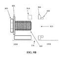
- FIG. 9B is a side view of the closure mechanism of FIG. 9A along line C-C′.
- FIG. 9C is a top view of the closure mechanism of FIG. 9A in a closed position.
- FIG. 10A is a top view of another embodiment of a closure mechanism in an open position.
- FIG. 10B is a top view of the closure mechanism of FIG. 10A in a closed position.
- FIG. 11A is an end view of another embodiment of a closure mechanism along line A-A′ of FIG. 4 in an open position.
- FIG. 11B is an end view of the closure mechanism of FIG. 11A in a closed position.
- FIG. 12A is an end view of another embodiment of a closure mechanism along line A-A′ of FIG. 4 in an open position.
- FIG. 12B is an end view of the closure mechanism of FIG. 12A in a closed position.
- FIG. 13 is a perspective view of a fairing.
- FIG. 14 is a flow chart illustrating one embodiment of a retrofitting process.
- FIG. 1A shows one embodiment of a VIV suppression device positioned around a support structure.
- the VIV suppression device may be a helical strake 100 positioned around a tubular 101 .
- Tubular 101 may be of any type of tubular including, but not limited to, a pipeline, riser, spar, tendon, buoy, rope, or cable.
- a single helical strake 100 is shown, it is to be understood that any number of helical strakes may be positioned along the length of tubular 101 .
- Helical strake 100 may include strake fins 112 extending from a body portion, in this case a strake sleeve 102 , which surrounds the underlying tubular 101 once installed. Fins 112 disrupt the normal flow around tubular 101 and in turn suppress VIV about tubular 101 . Any number of fins 112 may be attached to strake sleeve 102 , in this embodiment, three fins 112 are provided.
- Strake sleeve 102 may have a clam shell configuration in that it is formed by a first side 102 A and a second side 102 B that can be separated along opening 106 so that helical strake 100 can be placed around tubular 101 .
- opening 106 is formed along a longitudinal dimension of sleeve 102 .
- strake sleeve 102 may have a substantially cylindrical shape.
- strake sleeve 102 may have an inner diameter substantially the same as or slightly larger than tubular 101 or other underlying structure such that it fits around the tubular 101 or other structure.
- strake fins 112 have a substantially triangular cross-sectional shape, however, other shapes may be suitable (e.g., circular, square, etc.). It is noted, however, that helical strake 100 may be of any geometry with any number, size, and shape of fins.
- Helical strake 100 may be of any suitable length, but will typically be from about 4 feet to about 10 feet long.
- Strake fins 112 may be of any suitable height but will typically range from about 5 to about 50 percent of the tubular diameter, with 20 to 30 percent being the most common height range.
- the pitch of strake fins 112 may be of any suitable pitch, for example, within a range of from about 5 to about 25 times the tubular diameter, with 10-20 times the tubular diameter being most common.
- the number of fins may vary from about 1 to about 8, preferably from 3 to 4.
- Strake sleeve 102 and fins 112 may be made of any suitable material including, but not limited to, plastic, fiberglass, wood, metal, or synthetics such as rubber or fiber. Strake sleeve 102 and fins 112 may be made of the same or different materials. In some embodiments, strake sleeve 102 having fins 112 extending therefrom may be integrally formed as one piece. For example, strake sleeve 102 may be formed with fins 112 by an extrusion process that sets the helix of fins 112 as the material is drawn through the die. The helix may be set by the die by, for example, rotating the starting material as it is drawn through the die so that a desired helical angle is achieved.
- Suitable processes for integrally forming strake sleeve 102 with fins 112 may include an injection molding process, vacuum forming process or other similar process. Opening 106 may be molded into helical strake 100 or formed by a cutting operation after helical strake 100 is formed. It is noted, however, that in some embodiments, one or more portions of opening 106 may be omitted as discussed in more detail in reference to FIG. 3 .
- Helical strake 100 may be made of any material including, but not limited to, metal, plastic, fiberglass, synthetic, rubber, wood, or ceramic.
- helical strake 100 may be positioned around tubular 101 by separating sleeve sides 102 A, 102 B along opening 116 , formed along a side of sleeve 102 opposite opening 106 . Once sides 102 A, 102 B are separated, tubular 101 is inserted through opening 116 . Sides 102 A, 102 B are then closed around tubular 101 to secure helical strake 100 to tubular 101 .
- a retrofit installation of helical strake 100 about tubular 101 can be difficult and costly because special tooling to interface with a remote operated vehicle (ROV) is required to position and secure helical strake 100 around tubular 100 .
- ROV remote operated vehicle
- Such tooling can be expensive, difficult and unsafe to use, and requires a slow process for installation of the suppression devices.
- it can take months, or even years, to design and fabricate tooling for ROV installation of such helical strake configurations.
- helical strake 100 may include features which can be manipulated directly by the ROV or a diver performing the retrofit installation. Such features may include a biasing hinge mechanism 103 along opening 106 as well as handles 104 as illustrated in FIGS. 2A-2B and FIG. 3 . In addition, a securing mechanism 403 that can be easily manipulated by the ROV or diver may be positioned along opening 116 as illustrated in FIG. 4-FIG . 11 C.
- FIG. 2A illustrates a perspective view of one side of helical strake 100 including one or more of biasing hinge mechanism 103 positioned along opening 106 .
- Biasing hinge mechanism 103 may be configured to bias helical strake sleeve 102 in a closed position.
- biasing hinge mechanism 103 biases sleeve side 102 A toward 102 B, into the closed position.
- tubular 101 is forced through opening 116 of strake sleeve 102 , the installer (e.g., ROV or diver) does not have to exert a substantial force to close sleeve 102 around tubular 101 .
- the installer e.g., ROV or diver
- any number of biasing hinge mechanisms capable of achieving the desired biasing force may be positioned along opening 106 .
- three biasing hinge mechanisms 103 are provided, although one or more than three, for example, four or five, may be used.
- Biasing hinge mechanism 103 may be, in one embodiment, a spring hinge as illustrated in FIG. 2B .
- biasing hinge mechanism 103 may include brackets 107 which are attached to sleeve side 102 A and sleeve side 102 B along opening 106 .
- brackets 107 are attached to sleeve sides 102 A, 102 B using fasteners 109 (e.g., screws, bolts, pins or the like). It is contemplated, however, that brackets 107 may be attached by any suitable mechanism, e.g., welding, chemical boding, or the like.
- Pin 110 may extend through the interfacing ends of brackets 107 and along opening 106 .
- biasing member 108 may be positioned at each end of pin 110 .
- biasing member 108 may be a spring coil which is compressed when strake sleeve 102 is in the closed position and therefore provides a biasing force on helical strake 100 favoring the closed position.
- biasing hinge mechanism 103 may be used as a biasing hinge mechanism or, in another example, a compression or tension spring material may be directly connected to helical strake 100 or through brackets 107 .
- Biasing hinge mechanism 103 may be of any suitable size.
- Brackets 107 may be attached to helical strake sleeve 102 through fasteners 109 or may be welded, chemically bonded, or attached by any suitable means.
- Any number or type of biasing mechanism 108 may be attached along pin 110 , in this embodiment, two biasing mechanisms are attached at opposing ends of pin 110 .
- Biasing hinge mechanism 103 may also be made of any suitable material and may be made of more than one material. It is recognized that the optional biasing mechanism in biasing hinge mechanism 103 may be made of a temporary material since they are only used for installation.
- biasing hinge mechanism 103 The function of the biasing mechanisms, e.g. springs, in biasing hinge mechanism 103 is to keep the strake pressed against the tubular until the latches on the other side may be engaged. But some latching mechanisms will not require springs on the hinges since they may be closed to sufficiently impose pressure on the tubular without the need for a spring to impose pressure. Some devices, such as fairings, may use the same design and do not require pressure on the tubular. Biasing hinge mechanism 103 and handles 104 may be of any suitable design.
- Biasing hinge mechanism 103 including one or more of biasing mechanism 108 , pin 110 , brackets 107 , and fasteners 109 may be made of any suitable material including, but not limited to: metals such as Inconel, Elgiloy, Hastelloy, stainless steel, aluminum or copper; rubbers such as polyurethane, nitrile, or neoprene; plastics such as ABS, PVC, polyethylene, or Delrin; fiberglass; or wood. More than one material may be used to make any single component and more than one material may be utilized for the biasing hinge mechanism. It is noted that biasing mechanism 108 may be an optional feature in some embodiments, and may be made of a temporary material since they are only used during installation.
- Helical strake 100 may further include handle 104 which can be manipulated directly by the ROV or a diver performing the retrofit installation without the need for special tooling.
- handle 104 may be attached to strake sleeve 102 as desired.
- one handle 104 is attached to sleeve side 102 A and another handle 104 is attached to sleeve side 102 B.
- Handle 104 may have any structure capable of being used by an ROV or diver to open or close strake sleeve 102 around tubular 101 .
- handle 104 is any structure that protrudes from a surface of strake sleeve 102 .
- handle 104 may be a substantially ‘U’ shaped protrusion as illustrated in FIG. 2A .
- Handle 104 may be separately formed and attached to strake sleeve 102 , such as by welding, bolting, screwing or a chemical bonding process.
- handle 104 is integrally formed with strake sleeve 102 during fabrication of strake sleeve 102 .
- Handle 104 may be made of any suitable material including, but not limited to, metal, plastic, fiberglass, synthetic, rubber, wood, or ceramic.
- Helical strake 100 may further include fin opening 105 within fin 112 .
- Fin opening 105 may be formed within a portion of fin 112 along opening 106 to reduce interference when strake 100 is opened.
- FIG. 3 illustrates a perspective view of another embodiment of helical strake 100 in which opening 106 is formed along only a portion of helical strake 100 .
- opening 106 is formed at spaced apart locations along the length helical strake sleeve 102 .
- a biasing hinge mechanism 103 is positioned at each opening 106 .
- both the biasing hinge mechanism 103 and the material stiffness of strake sleeve 102 between each hinge 103 provide the biasing force which biases strake sleeve 102 into the closed position.
- biasing hinge mechanism 103 may be optional, and strake sleeve 102 formed without opening 106 .
- biasing hinge mechanism 103 and opening 106 are omitted, the material stiffness of strake sleeve 102 provides the biasing force and acts as the biasing mechanism to help close sleeve sides 102 A, 102 B around tubular 101 .
- FIG. 4 illustrates a perspective view of another side of helical strake 100 illustrated in FIG. 1A . From this view it can be seen that helical strake 100 includes closure mechanisms 403 that close opening 116 along helical strake sleeve 102 . An optional opening 405 in one or more of fins 112 may be utilized. When helical strake 100 is closed, closure mechanisms 403 are engaged to impose pressure on tubular 101 to keep helical strake 100 in place.
- Closure mechanism 403 may have any structure suitable for closing and securing strake side 102 A to strake side 102 B. Closure mechanisms 403 may be of any suitable material, but will typically be required to maintain their function in seawater for a time period measured in months or years. Representative closure mechanisms are described in reference to FIGS. 5A-11 . Closure mechanisms 403 may be of any suitable material, but will typically be required to maintain their function in seawater for a time period measured in months or years.
- closure mechanism 403 is a latch type mechanism that includes a latch arm 507 attached to pivot mechanism 508 , for example a hinge which, in turn, is attached to one of sides 102 A or 102 B of helical strake sleeve 102 .
- Latch receptacle 506 is attached to the other of sides 102 A and 102 B.
- Closure mechanism is configured such that notch 510 in latch receptacle 506 is of suitable design (i.e. not too deep) such that helical strake 100 imposes pressure on the tubular underneath it when closure mechanism 403 is closed.
- Closure mechanism 403 including latch plate 507 , latch receptacle 506 , and pivot mechanism 508 may be of any suitable size and shape. Variations of each of the components (geometric variations or otherwise) may be utilized to optimize the design for a given application. It is further noted that pivot mechanism 508 is optional, such that latch plate 507 and latch receptacle 506 may be designed to close sufficiently when latch plate 507 is set at a given angle. Other variations in the latch plate 507 and latch receptacle 506 are possible including any common latch. The invention is not restricted to a given latch design.
- Closure mechanism 403 including latch plate 507 , latch receptacle 506 , and pivot mechanism 508 may be of any suitable material including, but not limited to: metals such as Inconel, Elgiloy, Hastelloy, stainless steel, aluminum or copper; rubbers such as polyurethane, nitrile, or neoprene; plastics such as ABS, PVC, polyethylene, or Delrin; fiberglass; or wood. More than one material may be used to make any single component and more than one material may be utilized for closure mechanism 403 .
- FIG. 6A and FIG. 6B show another embodiment of a closure mechanism that may be used to hold opposing sides of a VIV suppression device together.
- FIG. 6A illustrates the closure mechanism of FIG. 4 along line A-A′
- FIG. 6B illustrates the closure mechanism of FIG. 4 along line A-A′.
- closure mechanism 403 includes a closure side 603 A and closure side 603 B, which are attached to sleeve sides 102 A, 102 B, respectively of helical strake 100 .
- Each of closure side 603 A and 603 B may have any sufficient profile capable of coming together at opening 116 and being held together, by for example, a cap 604 .
- closure sides 603 A and 603 B may comprise the profile of opposing sides of a bolt, serrated pin, or other profile.
- closure sides 603 A and 603 B are aligned with one another as illustrated in FIG. 6A .
- cap 604 is inserted over each side.
- cap 604 may have a handle 606 to facilitate handling of cap 604 by the ROV or diver performing the installation.
- Cap 604 is configured such that when it is pushed onto closure sides 603 A and 603 B, there is some interference which keeps cap 604 in place.
- cap 604 may have a size and shape complimentary to that of closure sides 603 A and 603 B, when they are aligned with one another in the closed position.
- Closure sides 603 A and 603 B may be of any suitable size. Cap 604 is designed to just fit over closure sides 603 A and 603 B and handle 606 may be of any suitable size that facilitates ease of installation by the ROV. Closure sides 603 A and 603 B may be molded as part of helical strake 100 or may be attached separately.
- Closure sides 603 A and 603 B, cap 604 , and handle 606 may be made of any suitable material, including, but not limited to: metals such as Inconel, Elgiloy, Hastelloy, stainless steel, aluminum or copper; rubbers such as polyurethane, nitrile, or neoprene; plastics such as ABS, PVC, polyethylene, or Delrin; fiberglass; or wood. More than one material may be used to make any single component and more than one material may be utilized for the latch system.
- cap 604 may be pulled off for removal of the suppression device. This feature allows the suppression device to be retrofitted numerous times at minimal cost.
- FIG. 6B illustrates a side view of closure mechanism 403 along line B-B′ of FIG. 4 .
- closure side 603 A may be of different cross section when viewed from one direction relative to the normal direction illustrated by FIG. 6A .
- closure sides 603 A and 603 B are depicted as comprising a conical or pyramidal shape in the figures, it is contemplated that closure sides 603 A and 603 B may join to form any suitable shape including square, rectangular, trapezoidal, or any suitable geometry. It is further noted that closure sides 603 A and 603 B do not need to be the same size nor are they required to mate exactly.
- FIG. 7 illustrates another embodiment of a closure mechanism along line A-A′ of FIG. 4 , which is similar to FIG. 6A , except that it includes mating mechanisms 705 A and 705 B.
- One of mating mechanisms 705 A, 705 B are attached to one of closure sides 703 A, 703 B on each side of opening 116 .
- Mating mechanisms 705 A, 705 B are configured to assist in holding closure sides 603 A, 603 B together prior to placement of cap 604 .
- mating mechanisms 705 A, 705 B are magnets which are attracted to one another. It is contemplated, however, that mating mechanisms 705 A, 705 B may be any type of mechanism capable of holding closure side 603 A against closure side 603 B.
- closure sides 603 A and 603 B come together, and the magnets contact each other and form a magnetic bond that keeps closure sides 603 A and 603 B adjacent to each other.
- this magnetic bond may be sufficient to hold sleeve sides 102 A, 102 B around tubular 101 and impose sufficient pressure (on itself or on an internal tubular) such that cap 604 is not required.
- Mating mechanisms 705 A, 705 B may be of any suitable shape, size, and in the case of magnets, strength. Representatively, the size of the magnets may be selected to provide a suitable magnetic force depending upon the actual application. Mating mechanisms 705 A, 705 B may be attached to closure sides 603 A and 603 B by any suitable means including, but not limited to, chemical bonding, magnetic bonding and mechanical fastening. Mating mechanisms 705 A, 705 B may be made of the same or different material as strake sleeve 102 . In the case of a magnetic material, the magnetic material may be any suitable magnetic material including, but not limited to, metals (ferro-magnets), rare earth materials, exotic materials, or any system that comprises an electrical circuit.
- FIG. 8 illustrates another embodiment of a closure mechanism along line A-A′ of FIG. 4 .
- Closure mechanism 403 may include closure side 803 A attached to sleeve side 102 A and closure side 803 B attached to sleeve side 102 B.
- Closure sides 803 A and 803 B may be substantially similar in operation as closure sides 603 A and 603 B described in reference to FIG. 7 , except that in this embodiment, they have a different profile.
- closure sides 603 A and 603 B may have barbs 810 a and 810 b which catch on receiving portions formed within cap 804 to hold sleeve sides 102 A and 102 B together.
- Closure mechanism 403 may further include mating mechanisms 805 A and 805 B similar to mating mechanisms 705 A and 705 B described in reference to FIG. 7 .
- FIG. 9A , FIG. 9B and FIG. 9C illustrate another embodiment of a closure mechanism.
- FIG. 9A illustrates the closure mechanism along line A-A′ of FIG. 4 when in an open position.
- FIG. 9B illustrates the closure mechanism along line C-C′ of FIG. 9A .
- FIG. 9C illustrates the closure mechanism of FIG. 9A in a closed position.
- Closure mechanism 403 may include a male housing 903 attached to sleeve side 102 A and female housing 904 attached to sleeve side 102 B. Each of male housing 903 and female housing 904 may be attached to their respective sides 102 A, 102 B along opening 116 .
- Male housing 903 may be a channel like structure dimensioned to maintain alignment of pin 905 with an opening 922 formed through female housing 904 when sides 102 A and 102 B are brought together as illustrated.
- male housing 903 may include side walls 910 , 912 which rest on a surface of sleeve side 102 A along opposing sides of pin 905 .
- Base member 914 may be positioned across a bottom end of side walls 910 , 912 and include an opening 920 through which pin 905 may be inserted.
- Male housing 903 may also include optional washer 906 which helps to support pin 905 at one end using clip 907 and/or stop 908 .
- Each of side walls 910 , 912 , base member 914 , washer 906 , clip 907 and stop 908 may be formed as separate pieces and then assembled together, or as one integrally formed piece that is, for example, molded from plastic.
- Female housing 904 which is attached to sleeve side 102 B, holds receptacle 909 in place.
- female housing 904 may be a bracket type structure that extends from the surface of sleeve side 102 B and faces opening 116 .
- Receptacle 909 may be a washer type structure in that it includes an opening for receiving pin 905 .
- Receptacle 909 may be attached to a side of female housing 904 opposite opening 116 , or it may be attached to the side facing opening 116 .
- Female housing 904 and male housing 903 may be attached to their respective sleeve side using any suitable attachment mechanism, e.g., bolting, screwing, welding, molding, chemical bonding or the like.
- pin 905 begins in a retracted position as illustrated by FIG. 9A and is held into place by either clip 907 or stop 908 .
- the ROV presses on pin 905 it is inserted through receptacle 909 as shown in FIG. 9C .
- sides 102 A and 102 B are now latched together.
- Male housing 903 , female housing 904 , receptacle 909 , pin 905 , washer 906 , clip 907 , and stop 908 may be made in any suitable size.
- pin 905 will range from 2 to 8 inches long and the accompanying hardware will be fit to match the pin size.
- Pin 905 may be of any suitable design but is designed to go through receptacle 909 with an interference fit on its threads 916 or appurtenances.
- Clip 907 may be of any suitable design and merely designates an attachment between male housing 903 and pin 905 that may be broken when the pin is inserted into receptacle 909 .
- Stop 908 may be of any suitable design and merely indicates an appurtenance that acts as an obstacle for pin 905 that can be passed when the pin 905 is inserted into receptacle 909 .
- One or more clips 907 and stops 909 are used to hold pin 905 in place before it is inserted, and any number or combination of clips or stops may be used.
- male housing 903 , female housing 904 , receptacle 909 , pin 905 , washer 906 , clip 907 , and stop 908 may be made of any suitable material including, but not limited to metal, plastic, rubber, fiberglass, synthetic, wood, or exotic materials.
- One pin 905 is inserted through receptacle 909 , parts of this latch system (for example, clip 907 or stop 908 , or parts of male housing 903 ) are no longer needed, and they may be made of a material that will corrode or dissolve in seawater.
- pin 905 may be a screw or bolt driven in by the ROV or diver.
- the head of pin 905 may be of any suitable size and may have a lanyard or other cabling attached to it to make it easier for the ROV or diver to grab and turn.
- pin 905 may be cut for removal of the suppression device. At the surface, pin 905 may then be replaced for reinstallation of the suppression device. This feature allows the suppression device to be retrofitted numerous times at minimal cost.
- FIG. 10A and FIG. 10B illustrate another embodiment of a closure mechanism along line A-A′ of FIG. 4 .
- Closure mechanism 403 is substantially the same as the closure mechanism described in reference to FIGS. 9A-9C , except in this embodiment, mating mechanisms 1010 A and 1010 B are attached to male housing 903 and female housing 904 .
- Mating mechanisms 1010 A and 1010 B may be substantially the same as mating mechanisms 705 A, 705 B, 805 A and 805 B described in reference to FIG. 7 and FIG. 8 .
- mating mechanisms 1010 A and 1010 B may be magnetic members attached to interfacing portions of male housing 903 and female housing 904 .
- mating mechanisms 1010 A and 1010 B allow for sleeve sides 102 A and 102 B to be temporarily magnetically bonded before pin 905 is inserted into receptacle 909 .
- the installation sequence includes bringing the device around the tubular and temporarily attaching sides 102 A and 102 B, and then using the insertion of pin 905 for a more permanent attachment.
- Pin 905 can also be a bolt, and/or may also have a spring under it to provide tension. It is further noted that in one embodiment, pin 905 may be a screw or bolt driven in by the ROV or diver.
- the head of pin 905 may be of any suitable size and may have a lanyard or other cabling attached to it to make it easier for the ROV or diver to grab and turn.
- FIG. 10A this figure shows sleeve side 102 A coming together with side 102 B.
- Male housing 903 which is on side 102 A, holds pin 905 and optional washer 906 using clip 907 and/or stop 908 to hold pin 905 in place.
- Female housing 904 which is on side 102 B, holds receptacle 909 in place.
- FIG. 11A and FIG. 11B illustrate another embodiment of a closure mechanism along line A-A′ of FIG. 4 .
- VIV suppression device sides for example, helical strake sleeve sides 102 A and 102 B, include extension members 1103 A and 1103 B which extend from interfacing ends of sleeve sides 102 A and 102 B.
- Extension members 1103 A and 1103 B may have a substantially ‘L’ shaped profile with the short arm perpendicular to the surface of sides 102 A and 102 B and the long arm parallel to the surface.
- Holes 1104 A and 1104 B may be formed through the short arm portions of each of extension members 1103 A and 1103 B.
- Holes 1104 A and 1104 B are dimensioned to receive clip portions 1107 A, 1107 B which extend inward from side walls 1110 A and 1110 B of cap 1105 .
- Side walls 1110 A and 1110 B extend from a base member 1106 of cap 1105 .
- Extension members 1103 A and 1103 B may be devices sides 102 A, 102 B (i.e. integrally formed with), or may be attached separately. Cap 1105 may also have a handle for ease of installation (not shown).
- cap 1105 includes a spring
- additional closing pressure is brought onto sleeve sides 102 A and 102 B of the VIV suppression device (e.g., helical strake) and may impart additional pressure onto the tubular to which it is attached.
- the spring can serve to mitigate changes in the tubular diameter due to hydrostatic pressure, or other causes.
- Cap 1105 , extension members 1103 A and 1103 B, clips 1107 A and 1107 B, and base member 1106 may be made of any suitable material such as any of the previously discussed materials.
- FIG. 12A and FIG. 12B illustrate another embodiment of a of a closure mechanism along line A-A′ of FIG. 4 .
- Closure mechanism 403 is substantially the same as that described in reference to FIGS. 11A-11B , except that instead of having a cap to hold device sides 102 A and 102 B together, extension members 1103 A and 1103 B overlap one another and are secured together using pin 1209 .
- holes 1208 A and 1208 B are formed along the top portions of extension members 1103 A and 1103 B. Holes 1208 A and 1208 B are dimensioned to overlap one another and receive pin 1209 .
- Pin 1209 may include appurtenances 1210 which, in one embodiment, provide an interference fit between pin 1209 and holes 1208 A and 1208 B.
- pin 1209 can be inserted into the holes to lock then together, and in turn, secure the VIV suppression device around the underlying structure.
- Pin 1209 may consist of any reasonable structure that allows its insertion into the holes 1208 A, 1208 B, thus pin 1209 and holes 1208 A and 1208 B may be of any reasonable geometry. Pin 1209 may be tapered to ease installation or to help insure that it stays in place. Pin 1209 may be further locked into place by other mechanical means. Appurtenances 1210 may consist of any suitable geometry and may act as springs or may simply provide interference with holes 1208 A and 1208 B.
- pin 1209 , extension members 1103 A and 1103 B, and appurtenances 1210 may be of any suitable size, shape, or material, with their exact size, shape, and material determined by the requirements of their application.
- biasing hinge mechanisms and closure mechanisms are described in reference to helical strake 100 , they may be used with any type of VIV suppression device configured to encircle and be attached around, an underlying structure such as a tubular.
- any one or more of the previously discussed biasing hinge mechanisms and closure mechanisms may be used to attach a fairing such as that illustrated in FIG. 13 to an underlying structure.
- fairing 1302 includes an opening 1304 along one side similar to the opening 116 described in reference to the previous figures. Any of the previously discussed closure mechanisms 403 may be used to hold fairing side 1302 A together with fairing side 1302 B.
- fairing includes a second opening along the opposite side
- such opening could be configured to have any one or more of the previously discussed biasing hinge mechanisms to bias fairing sides 1302 A and 1302 B into the closed position around an underlying tubular.
- VIV suppression devices may include, helical strakes, fairings, a VIV suppression device that encircles the underlying tubular and has other shapes and sizes (e.g., round, square, rectangular, etc.) and collars.
- VIV suppression devices disclosed herein may be attached to the underlying tubular structure by retrofitting using an ROV or diver, or prior to installation of the tubular structure.
- a retrofit installation process is illustrated in the flowchart of FIG. 14 .
- flow chart 1400 illustrates a retrofit installation processing which includes lowering of the VIV suppression device (e.g., helical strake 100 ) down to the desired region of the tubular, which is underwater using, for example, a diver, ROV, winch line or other suitable mechanism (block 1402 ).
- the diver or ROV may be used to open the VIV device (block 1404 ) and insert the device around the tubular structure (block 1406 ) according to the previously discussed techniques.
- the diver or ROV can close the device around the tubular (block 1408 ).
- the biasing hinge mechanism previously discussed which is attached between the sides, biases the sides toward one another to facilitate closing of the device around the tubular.
- the diver or ROV may further secure the sides of the device to one another by manipulating any of the above described closure mechanisms.
- the diver or ROV may rotate the device around the tubular such that the opening and closure mechanisms are facing the diver or ROV. In this manner, the diver or ROV may more easily manipulate the closure mechanism. It is noted that each of the retrofit installation steps described herein may be performed by the ROV or diver without any special tooling.
- biasing hinge mechanism and closure mechanisms may be directly manipulated by components already present on exiting ROV devices or by hand by the diver.
- retrofit installation using any of the above described VIV devices is simpler and more cost effective than existing methodologies which require special tooling.
- the VIV devices may be placed in an open configuration, positioned adjacent the tubular structure and then closed around the tubular structure. The tubular structure may then be lowered down through the water to the sea floor.
Abstract
Description
Claims (19)
Priority Applications (1)
| Application Number | Priority Date | Filing Date | Title |
|---|---|---|---|
| US13/594,450 US9080392B1 (en) | 2011-08-25 | 2012-08-24 | Vortex-induced vibration suppression devices for retrofitting |
Applications Claiming Priority (2)
| Application Number | Priority Date | Filing Date | Title |
|---|---|---|---|
| US201161527416P | 2011-08-25 | 2011-08-25 | |
| US13/594,450 US9080392B1 (en) | 2011-08-25 | 2012-08-24 | Vortex-induced vibration suppression devices for retrofitting |
Publications (1)
| Publication Number | Publication Date |
|---|---|
| US9080392B1 true US9080392B1 (en) | 2015-07-14 |
Family
ID=53506684
Family Applications (1)
| Application Number | Title | Priority Date | Filing Date |
|---|---|---|---|
| US13/594,450 Expired - Fee Related US9080392B1 (en) | 2011-08-25 | 2012-08-24 | Vortex-induced vibration suppression devices for retrofitting |
Country Status (1)
| Country | Link |
|---|---|
| US (1) | US9080392B1 (en) |
Cited By (9)
| Publication number | Priority date | Publication date | Assignee | Title |
|---|---|---|---|---|
| CN106014275A (en) * | 2016-07-07 | 2016-10-12 | 哈尔滨工程大学 | Novel vortex-induced vibration resisting bionic riser |
| CN106909712A (en) * | 2017-01-12 | 2017-06-30 | 王炳超 | The method for designing of the offset frequency type progressive rate leaf spring tangent line camber such as the main spring formula of two-stage is non- |
| CN107701122A (en) * | 2017-11-01 | 2018-02-16 | 西南石油大学 | The standpipe vortex-induced vibration suppression device and method that a kind of Fenestration drainage is combined with swing |
| CN108571497A (en) * | 2017-03-08 | 2018-09-25 | 中国科学院力学研究所 | A kind of vortex-induced vibration suppression device |
| US10473131B1 (en) * | 2016-07-10 | 2019-11-12 | VIV Solutions LLC | Helical strakes and collar |
| CN113983041A (en) * | 2021-11-02 | 2022-01-28 | 西南石油大学 | Marine riser vortex-induced vibration suppression device |
| US11261670B1 (en) * | 2019-07-08 | 2022-03-01 | VIV Solutions LLC | VIV suppression for retrofit with minimal tooling |
| US11261675B2 (en) | 2018-01-16 | 2022-03-01 | VIV Solutions LLC | Methods for constructing a helical strake segment using one or more shell sections and fins |
| US11946571B1 (en) * | 2020-01-16 | 2024-04-02 | Allan John Edwards, IV | Temporary pipeline protection apparatus |
Citations (7)
| Publication number | Priority date | Publication date | Assignee | Title |
|---|---|---|---|---|
| US5507243A (en) * | 1994-02-23 | 1996-04-16 | The Laitram Corporation | Connector for underwater cables |
| US6048136A (en) * | 1996-07-19 | 2000-04-11 | Shell Oil Company | Vortex induced vibration protection for deepwater drilling risers |
| US6113313A (en) * | 1996-06-11 | 2000-09-05 | Slickbar Products Corporation | Pile wrapper and clamping assembly |
| US20020146287A1 (en) * | 2000-07-26 | 2002-10-10 | Allen Donald Wayne | Methods and systems for reducing drag and vortex-induced vibrations on cylindrical structures |
| US6896447B1 (en) * | 2000-11-14 | 2005-05-24 | Weldon Taquino | Vortex induced vibration suppression device and method |
| US20100146734A1 (en) * | 2008-12-16 | 2010-06-17 | Munson Dennis J | Control hinge for stabilizing door |
| US20100156088A1 (en) * | 2004-11-12 | 2010-06-24 | Viv Suppression, Inc. | Rov friendly vortex induced vibration inhibitor and method of use |
-
2012
- 2012-08-24 US US13/594,450 patent/US9080392B1/en not_active Expired - Fee Related
Patent Citations (7)
| Publication number | Priority date | Publication date | Assignee | Title |
|---|---|---|---|---|
| US5507243A (en) * | 1994-02-23 | 1996-04-16 | The Laitram Corporation | Connector for underwater cables |
| US6113313A (en) * | 1996-06-11 | 2000-09-05 | Slickbar Products Corporation | Pile wrapper and clamping assembly |
| US6048136A (en) * | 1996-07-19 | 2000-04-11 | Shell Oil Company | Vortex induced vibration protection for deepwater drilling risers |
| US20020146287A1 (en) * | 2000-07-26 | 2002-10-10 | Allen Donald Wayne | Methods and systems for reducing drag and vortex-induced vibrations on cylindrical structures |
| US6896447B1 (en) * | 2000-11-14 | 2005-05-24 | Weldon Taquino | Vortex induced vibration suppression device and method |
| US20100156088A1 (en) * | 2004-11-12 | 2010-06-24 | Viv Suppression, Inc. | Rov friendly vortex induced vibration inhibitor and method of use |
| US20100146734A1 (en) * | 2008-12-16 | 2010-06-17 | Munson Dennis J | Control hinge for stabilizing door |
Cited By (11)
| Publication number | Priority date | Publication date | Assignee | Title |
|---|---|---|---|---|
| CN106014275A (en) * | 2016-07-07 | 2016-10-12 | 哈尔滨工程大学 | Novel vortex-induced vibration resisting bionic riser |
| US10473131B1 (en) * | 2016-07-10 | 2019-11-12 | VIV Solutions LLC | Helical strakes and collar |
| CN106909712A (en) * | 2017-01-12 | 2017-06-30 | 王炳超 | The method for designing of the offset frequency type progressive rate leaf spring tangent line camber such as the main spring formula of two-stage is non- |
| CN106909712B (en) * | 2017-01-12 | 2020-07-28 | 王炳超 | Design method for tangential arc height of two-stage main spring type unequal frequency bias gradient stiffness plate spring |
| CN108571497A (en) * | 2017-03-08 | 2018-09-25 | 中国科学院力学研究所 | A kind of vortex-induced vibration suppression device |
| CN107701122A (en) * | 2017-11-01 | 2018-02-16 | 西南石油大学 | The standpipe vortex-induced vibration suppression device and method that a kind of Fenestration drainage is combined with swing |
| US11261675B2 (en) | 2018-01-16 | 2022-03-01 | VIV Solutions LLC | Methods for constructing a helical strake segment using one or more shell sections and fins |
| US11261670B1 (en) * | 2019-07-08 | 2022-03-01 | VIV Solutions LLC | VIV suppression for retrofit with minimal tooling |
| US11946571B1 (en) * | 2020-01-16 | 2024-04-02 | Allan John Edwards, IV | Temporary pipeline protection apparatus |
| CN113983041A (en) * | 2021-11-02 | 2022-01-28 | 西南石油大学 | Marine riser vortex-induced vibration suppression device |
| CN113983041B (en) * | 2021-11-02 | 2024-01-12 | 西南石油大学 | Vortex-induced vibration suppression device for marine riser |
Similar Documents
| Publication | Publication Date | Title |
|---|---|---|
| US9080392B1 (en) | Vortex-induced vibration suppression devices for retrofitting | |
| US8475085B2 (en) | ROV friendly vortex induced vibration inhibitor and method of use | |
| US8511245B2 (en) | Helical strake systems | |
| US20130064607A1 (en) | Underwater Device for ROV Installable Tools | |
| US8727667B2 (en) | Vortex-induced vibration suppression device and mating collar system | |
| US6561734B1 (en) | Partial helical strake for vortex-induced-vibrationsuppression | |
| US6928709B2 (en) | Apparatus for remote installation of devices for reducing drag and vortex induced vibration | |
| US5984584A (en) | Fairings for drilling riser control pod hoses | |
| US9511825B1 (en) | Apparatus for suppressing vortex-induced vibration of a structure with reduced coverage | |
| US9677688B1 (en) | Fairing having an offset opening | |
| US7406923B2 (en) | Systems and methods for reducing vibrations | |
| US8770894B1 (en) | Helical strakes with molded in stand-offs | |
| US8882066B2 (en) | Buoyant clamp for tubular members | |
| US20080025800A1 (en) | Fairing for marine drilling risers | |
| US10473131B1 (en) | Helical strakes and collar | |
| US9080610B1 (en) | Vortex suppression fairings | |
| EP2049805A2 (en) | Twin fin fairing | |
| CA2813023A1 (en) | Tubing grab assembly | |
| US9534618B1 (en) | Fairing bodies with multiple parts | |
| US10337649B1 (en) | Strake system | |
| US10865910B1 (en) | Coupled fairing systems | |
| US20090252558A1 (en) | Underwater device for rov installable tools | |
| WO2010141436A2 (en) | Vortex induced vibration suppression systems and methods | |
| US9074426B1 (en) | Method and apparatus for accommodating tubular diameter changes | |
| US11261670B1 (en) | VIV suppression for retrofit with minimal tooling |
Legal Events
| Date | Code | Title | Description |
|---|---|---|---|
| AS | Assignment |
Owner name: VIV SOLUTIONS LLC, TEXAS Free format text: ASSIGNMENT OF ASSIGNORS INTEREST;ASSIGNORS:ALLEN, DONALD WAYNE;WEST, WILLIAM ANDREW;DEHNE, JULIE ANN;AND OTHERS;SIGNING DATES FROM 20120822 TO 20120824;REEL/FRAME:028847/0506 Owner name: VIV SOLUTIONS LLC, TEXAS Free format text: ASSIGNMENT OF ASSIGNORS INTEREST;ASSIGNORS:ALLEN, DONALD WAYNE;WEST, WILLIAM ANDREW;DEHNE, JULIE ANN;AND OTHERS;SIGNING DATES FROM 20120822 TO 20120824;REEL/FRAME:028847/0154 |
|
| AS | Assignment |
Owner name: VIV SOLUTIONS LLC, TEXAS Free format text: CORRECTIVE ASSIGNMENT TO CORRECT THE TO REMOVE ASSIGNMENT RECORD FILED IN THE INCORRECT APPLICATION NO. 13/584,450 PREVIOUSLY RECORDED ON REEL 028847 FRAME 0154. ASSIGNOR(S) HEREBY CONFIRMS THE ASSIGNMENT;ASSIGNORS:ALLEN, DONALD WAYNE;WEST, WILLIAM ANDREW;DEHNE, JULIE ANN;AND OTHERS;SIGNING DATES FROM 20120822 TO 20120824;REEL/FRAME:028943/0905 |
|
| STCF | Information on status: patent grant |
Free format text: PATENTED CASE |
|
| FEPP | Fee payment procedure |
Free format text: MAINTENANCE FEE REMINDER MAILED (ORIGINAL EVENT CODE: REM.); ENTITY STATUS OF PATENT OWNER: SMALL ENTITY |
|
| LAPS | Lapse for failure to pay maintenance fees |
Free format text: PATENT EXPIRED FOR FAILURE TO PAY MAINTENANCE FEES (ORIGINAL EVENT CODE: EXP.); ENTITY STATUS OF PATENT OWNER: SMALL ENTITY |
|
| STCH | Information on status: patent discontinuation |
Free format text: PATENT EXPIRED DUE TO NONPAYMENT OF MAINTENANCE FEES UNDER 37 CFR 1.362 |
|
| FP | Expired due to failure to pay maintenance fee |
Effective date: 20190714 |