US5983654A - Freezer-equipped refrigerator - Google Patents

Freezer-equipped refrigerator Download PDF

Info

Publication number
US5983654A
US5983654A US08/861,804 US86180497A US5983654A US 5983654 A US5983654 A US 5983654A US 86180497 A US86180497 A US 86180497A US 5983654 A US5983654 A US 5983654A
Authority
US
United States
Prior art keywords
cool air
freezer
sections
air supply
opening
Prior art date
Legal status (The legal status is an assumption and is not a legal conclusion. Google has not performed a legal analysis and makes no representation as to the accuracy of the status listed.)
Expired - Fee Related
Application number
US08/861,804
Inventor
Kazu Yamamoto
Toshie Hiraoka
Mutsumi Kato
Katsumasa Sakamoto
Kunihiko Yagi
Current Assignee (The listed assignees may be inaccurate. Google has not performed a legal analysis and makes no representation or warranty as to the accuracy of the list.)
Mitsubishi Electric Corp
Original Assignee
Mitsubishi Electric Corp
Priority date (The priority date is an assumption and is not a legal conclusion. Google has not performed a legal analysis and makes no representation as to the accuracy of the date listed.)
Filing date
Publication date
Application filed by Mitsubishi Electric Corp filed Critical Mitsubishi Electric Corp
Assigned to MITSUBISHI DENKI KABUSHIKI KAISHA reassignment MITSUBISHI DENKI KABUSHIKI KAISHA ASSIGNMENT OF ASSIGNORS INTEREST (SEE DOCUMENT FOR DETAILS). Assignors: HIRAOKA, TOSHIE, KATO, MUTSUMI, SAKAMOTO, KATSUMASA, YAGI, KUNIHIKO, YAMAMOTO, KAZU
Assigned to MITSUBISHI DENKI KABUSHIKI KAISHA reassignment MITSUBISHI DENKI KABUSHIKI KAISHA (ASSIGNMENT OF ASSIGNOR'S INTEREST) RE-RECORDED TO CORRECT THE RECORDATION DATE OF 04-06-98 TO 04-07-98 PREVIOUSLY RECORDED AT REEL 9096, FRAME 0750. Assignors: HIRAOKA, TOSHIE, KATO, MUTSUMI, SAKAMOTO, KATSUMASA, YAGI, KUNIHIKO, YAMAMOTO, KAZU
Application granted granted Critical
Publication of US5983654A publication Critical patent/US5983654A/en
Anticipated expiration legal-status Critical
Expired - Fee Related legal-status Critical Current

Links

Images

Classifications

    • FMECHANICAL ENGINEERING; LIGHTING; HEATING; WEAPONS; BLASTING
    • F25REFRIGERATION OR COOLING; COMBINED HEATING AND REFRIGERATION SYSTEMS; HEAT PUMP SYSTEMS; MANUFACTURE OR STORAGE OF ICE; LIQUEFACTION SOLIDIFICATION OF GASES
    • F25DREFRIGERATORS; COLD ROOMS; ICE-BOXES; COOLING OR FREEZING APPARATUS NOT OTHERWISE PROVIDED FOR
    • F25D17/00Arrangements for circulating cooling fluids; Arrangements for circulating gas, e.g. air, within refrigerated spaces
    • F25D17/04Arrangements for circulating cooling fluids; Arrangements for circulating gas, e.g. air, within refrigerated spaces for circulating air, e.g. by convection
    • F25D17/06Arrangements for circulating cooling fluids; Arrangements for circulating gas, e.g. air, within refrigerated spaces for circulating air, e.g. by convection by forced circulation
    • F25D17/062Arrangements for circulating cooling fluids; Arrangements for circulating gas, e.g. air, within refrigerated spaces for circulating air, e.g. by convection by forced circulation in household refrigerators
    • F25D17/065Arrangements for circulating cooling fluids; Arrangements for circulating gas, e.g. air, within refrigerated spaces for circulating air, e.g. by convection by forced circulation in household refrigerators with compartments at different temperatures
    • FMECHANICAL ENGINEERING; LIGHTING; HEATING; WEAPONS; BLASTING
    • F25REFRIGERATION OR COOLING; COMBINED HEATING AND REFRIGERATION SYSTEMS; HEAT PUMP SYSTEMS; MANUFACTURE OR STORAGE OF ICE; LIQUEFACTION SOLIDIFICATION OF GASES
    • F25DREFRIGERATORS; COLD ROOMS; ICE-BOXES; COOLING OR FREEZING APPARATUS NOT OTHERWISE PROVIDED FOR
    • F25D29/00Arrangement or mounting of control or safety devices
    • FMECHANICAL ENGINEERING; LIGHTING; HEATING; WEAPONS; BLASTING
    • F25REFRIGERATION OR COOLING; COMBINED HEATING AND REFRIGERATION SYSTEMS; HEAT PUMP SYSTEMS; MANUFACTURE OR STORAGE OF ICE; LIQUEFACTION SOLIDIFICATION OF GASES
    • F25DREFRIGERATORS; COLD ROOMS; ICE-BOXES; COOLING OR FREEZING APPARATUS NOT OTHERWISE PROVIDED FOR
    • F25D17/00Arrangements for circulating cooling fluids; Arrangements for circulating gas, e.g. air, within refrigerated spaces
    • F25D17/04Arrangements for circulating cooling fluids; Arrangements for circulating gas, e.g. air, within refrigerated spaces for circulating air, e.g. by convection
    • F25D17/042Air treating means within refrigerated spaces
    • F25D17/045Air flow control arrangements
    • FMECHANICAL ENGINEERING; LIGHTING; HEATING; WEAPONS; BLASTING
    • F25REFRIGERATION OR COOLING; COMBINED HEATING AND REFRIGERATION SYSTEMS; HEAT PUMP SYSTEMS; MANUFACTURE OR STORAGE OF ICE; LIQUEFACTION SOLIDIFICATION OF GASES
    • F25DREFRIGERATORS; COLD ROOMS; ICE-BOXES; COOLING OR FREEZING APPARATUS NOT OTHERWISE PROVIDED FOR
    • F25D2317/00Details or arrangements for circulating cooling fluids; Details or arrangements for circulating gas, e.g. air, within refrigerated spaces, not provided for in other groups of this subclass
    • F25D2317/06Details or arrangements for circulating cooling fluids; Details or arrangements for circulating gas, e.g. air, within refrigerated spaces, not provided for in other groups of this subclass with forced air circulation
    • F25D2317/065Details or arrangements for circulating cooling fluids; Details or arrangements for circulating gas, e.g. air, within refrigerated spaces, not provided for in other groups of this subclass with forced air circulation characterised by the air return
    • F25D2317/0651Details or arrangements for circulating cooling fluids; Details or arrangements for circulating gas, e.g. air, within refrigerated spaces, not provided for in other groups of this subclass with forced air circulation characterised by the air return through the bottom
    • FMECHANICAL ENGINEERING; LIGHTING; HEATING; WEAPONS; BLASTING
    • F25REFRIGERATION OR COOLING; COMBINED HEATING AND REFRIGERATION SYSTEMS; HEAT PUMP SYSTEMS; MANUFACTURE OR STORAGE OF ICE; LIQUEFACTION SOLIDIFICATION OF GASES
    • F25DREFRIGERATORS; COLD ROOMS; ICE-BOXES; COOLING OR FREEZING APPARATUS NOT OTHERWISE PROVIDED FOR
    • F25D2317/00Details or arrangements for circulating cooling fluids; Details or arrangements for circulating gas, e.g. air, within refrigerated spaces, not provided for in other groups of this subclass
    • F25D2317/06Details or arrangements for circulating cooling fluids; Details or arrangements for circulating gas, e.g. air, within refrigerated spaces, not provided for in other groups of this subclass with forced air circulation
    • F25D2317/065Details or arrangements for circulating cooling fluids; Details or arrangements for circulating gas, e.g. air, within refrigerated spaces, not provided for in other groups of this subclass with forced air circulation characterised by the air return
    • F25D2317/0653Details or arrangements for circulating cooling fluids; Details or arrangements for circulating gas, e.g. air, within refrigerated spaces, not provided for in other groups of this subclass with forced air circulation characterised by the air return through the mullion
    • FMECHANICAL ENGINEERING; LIGHTING; HEATING; WEAPONS; BLASTING
    • F25REFRIGERATION OR COOLING; COMBINED HEATING AND REFRIGERATION SYSTEMS; HEAT PUMP SYSTEMS; MANUFACTURE OR STORAGE OF ICE; LIQUEFACTION SOLIDIFICATION OF GASES
    • F25DREFRIGERATORS; COLD ROOMS; ICE-BOXES; COOLING OR FREEZING APPARATUS NOT OTHERWISE PROVIDED FOR
    • F25D2317/00Details or arrangements for circulating cooling fluids; Details or arrangements for circulating gas, e.g. air, within refrigerated spaces, not provided for in other groups of this subclass
    • F25D2317/06Details or arrangements for circulating cooling fluids; Details or arrangements for circulating gas, e.g. air, within refrigerated spaces, not provided for in other groups of this subclass with forced air circulation
    • F25D2317/067Details or arrangements for circulating cooling fluids; Details or arrangements for circulating gas, e.g. air, within refrigerated spaces, not provided for in other groups of this subclass with forced air circulation characterised by air ducts
    • FMECHANICAL ENGINEERING; LIGHTING; HEATING; WEAPONS; BLASTING
    • F25REFRIGERATION OR COOLING; COMBINED HEATING AND REFRIGERATION SYSTEMS; HEAT PUMP SYSTEMS; MANUFACTURE OR STORAGE OF ICE; LIQUEFACTION SOLIDIFICATION OF GASES
    • F25DREFRIGERATORS; COLD ROOMS; ICE-BOXES; COOLING OR FREEZING APPARATUS NOT OTHERWISE PROVIDED FOR
    • F25D2400/00General features of, or devices for refrigerators, cold rooms, ice-boxes, or for cooling or freezing apparatus not covered by any other subclass
    • F25D2400/04Refrigerators with a horizontal mullion
    • FMECHANICAL ENGINEERING; LIGHTING; HEATING; WEAPONS; BLASTING
    • F25REFRIGERATION OR COOLING; COMBINED HEATING AND REFRIGERATION SYSTEMS; HEAT PUMP SYSTEMS; MANUFACTURE OR STORAGE OF ICE; LIQUEFACTION SOLIDIFICATION OF GASES
    • F25DREFRIGERATORS; COLD ROOMS; ICE-BOXES; COOLING OR FREEZING APPARATUS NOT OTHERWISE PROVIDED FOR
    • F25D2700/00Means for sensing or measuring; Sensors therefor
    • F25D2700/12Sensors measuring the inside temperature
    • F25D2700/123Sensors measuring the inside temperature more than one sensor measuring the inside temperature in a compartment

Definitions

  • the present invention relates to a cool air supply in a freezer-equipped refrigerator.
  • FIGS. 13 to 16 show conventional cool air wind passage structures.
  • FIG. 13 is an appearance view of a conventional freezer-equipped refrigerator.
  • FIG. 14 is a transparent perspective view showing a cool air wind structure of the conventional freezer-equipped refrigerator.
  • a freezer-equipped refrigerator 1 includes a refrigerating chamber 2 and freezing chambers 3 located below the refrigerating chamber 2.
  • the freezing chamber 3 incorporates a heat exchanger 4 and a fan 5 for circulating cool air located above the fan 5.
  • the cool wind blown off from the fan 5 is branched into several areas. It blows off into the refrigerating chamber 2 as follows.
  • FIG. 15 shows a control substrate 80 for controlling whether or not the circulation of cool wind should be carried out.
  • the 16 is a flowchart of a control of the circulation of cool wind.
  • the element 12 detects that the temperature of the refrigerating chamber 2 is higher than a setting value
  • the fan 5 rotates and the damper 7 opens so that cool wind is supplied to the respective shelves of the refrigerating chamber 2.
  • a compressor for supplying refrigerant to the heat exchanger is rotating.
  • the damper 7 is closed.
  • the fan 5, in accordance with the temperature of other chambers, continues to rotate or stops. By the repetition of such an operation, the temperature of the refrigerating chamber 2 is controlled so as to be constant.
  • the conventional freezer-equipped refrigerator has the following problems. If the chamber in a uniform temperature zone are sectioned by plural shelves or boxes, the temperature difference between the temperature of the element 12 and the sectioned places is increased. Accordingly, it is difficult to maintain the temperature of the refrigerating chamber at a predetermined temperature. Additionally, when the door of the refrigerating chamber 2 is opened, the temperature of the refrigerating chamber 2 increases. However, the temperature does not increase uniformly, and the temperature of an upper zone is increased. If the setting value is lowered in order to suppress such a phenomenon, inversely the temperature of the lowest section becomes lower than the setting value.
  • a freezer-equipped refrigerator comprises: a refrigerating chamber; a freezing chamber; a plurality of sections formed within at least one of the refrigerating chamber and the freezing chamber, a setting temperature of the sections being substantially equal; temperature detecting means provided in each of the sections, for detecting a temperature of each section; a plurality of cool air supply ducts each having at least one cool air blow-off opening for supplying the cool air to each of the sections, the number of the cool air supply ducts being equal to the number of the temperature detecting means or the sections; opening/closing means for opening/closing an inlet for sucking the cool air into the cool air supply duct; and control means for controlling the open/close of the opening/closing means.
  • the temperature of a plurality of sections formed in the refrigerating chamber or a freezing chamber can be uniform.
  • FIG. 1 is a general view of a freezer-equipped refrigerator
  • FIG. 2 is a perspective view showing the cool wind circulating wind passage of a freezer-equipped refrigerator according to the first embodiment according to the present invention
  • FIG. 3 is a schematic view of a control substrate for controlling whether the circulation of cool wind should be effected in a freezer-equipped refrigerator according to the first embodiment
  • FIG. 4 is a control flowchart for controlling whether the circulation of cool wind should be effected in a freezer-equipped refrigerator according to the first embodiment
  • FIG. 5 is a perspective view showing the cool wind circulating wind passage of a freezer-equipped refrigerator according to the first embodiment according to the present invention
  • FIG. 6 is a table showing the relationship between each of the detected values of elements of a freezer-equipped refrigerator and open/close of each damper
  • FIG. 7 is a schematic view of a control substrate for controlling whether the circulation of cool wind should be effected in a freezer-equipped refrigerator according to the third embodiment
  • FIG. 8 is a view showing the relationship between the detected values and the standing point of a wind adjusting damper in a freezer-equipped refrigerator according to the third embodiment
  • FIG. 9 is a perspective view showing the cool wind circulating passage in a freezer-equipped refrigerator according to the third embodiment.
  • FIG. 10 is a view showing the relationship between the detected values and the standing point of a wind adjusting damper in a freezer-equipped refrigerator according to the third embodiment
  • FIGS. 11A and 11B are perspective views showing the cool wind circulating passage in a freezer-equipped refrigerator according to the fourth embodiment
  • FIG. 12 is a perspective view showing the control wind circulating passage in a freezer-equipped refrigerator according to the fifth embodiment
  • FIG. 13 is an appearance view of the conventional freezer-equipped refrigerator
  • FIG. 14 is a perspective view of a cool air passage structure of the conventional freezer-equipped refrigerator.
  • FIG. 15 is a schematic view showing the control substrate 80 for controlling whether or not the circulation of cool air should be carried out in a conventional freezer-equipped refrigerator.
  • FIG. 16 is a control flowchart for controlling whether or not the circulation of cool air should be carried out in a conventional freezer-equipped refrigerator.
  • FIG. 1 is a perspective view showing a cool wind circulating passage of a freezer-equipped refrigerator according to the embodiment of the present invention.
  • FIG. 2 is an enlarged view of the main part in FIG. 1.
  • the freezer-equipped refrigerator 1 includes a refrigerating chamber 2 including two sections 23 and 26 (see, FIG. 2) having setting temperature of 0-10° and a freezing chamber 3 located below the refrigerating chamber 2.
  • the refrigerating chamber 2 is divided into the sections 23 and 26 by a partition plate 91.
  • This partition plate may be a plate-like plate, a net-like plate or the like. However, it is possible to omit the partition plate 91 in this embodiment.
  • FIG. 1 is a perspective view showing a cool wind circulating passage of a freezer-equipped refrigerator according to the embodiment of the present invention.
  • FIG. 2 is an enlarged view of the main part in FIG. 1.
  • the freezer-equipped refrigerator 1 includes a refrigerating chamber 2 including two sections 23 and 26 (see, FIG. 2) having setting temperature of
  • the freezing chamber 3 incorporates a heat exchanger 4 and a fan 5 for circulating cool air located above the heat exchanger 4.
  • the cool wind blown off from the fan 5 is branched into several areas. It blows off into the refrigerating chamber 2 as follows. It is taken in from inlet 6, passes a box 90 in which a wind passage may be provided to communicate with each damper of a twin damper 20 or a base plate may be installed, and reaches a twin damper 20 which is a damper portion having a plurality of dampers.
  • An UP damper 20A which is one of the plural opening/closing inlets serves to open/close an upper section duct 21 whereas an LR damper 20B which is also one of the plural closing opening/closing inlets serves to open/close a lower section duct 22.
  • An upper section 23 is provided with a first temperature detecting element 24 which is one of temperature detecting elements whereas a lower section 26 is provided with a second temperature detecting element 25 which is also one of the temperature detecting elements.
  • the upper section duct 21 and lower section duct 22 are provided with cool air blow-off openings 9 at the intermediate position and distal positions of tubes, which blow off the cool wind.
  • the blown-off cool wind cools the food and others within the refrigerating chamber 2 and is drawn into an inhalation opening 10.
  • the cool wind further passes a return wind passage 11 to return to the lower part of the heat exchanger 4. Then, the cool wind is rid of heat again by the heat exchanger 4 and sent to the refrigerating chamber 2 and others. Such
  • the refrigerating chamber 2 is divided to an upper section 23 and a lower section 26 by a separating plate 91.
  • the refrigerating chamber 2 may be divided into three or more sections.
  • the separating plate may be a plate-shaped plate, a net-shaped plate or the like.
  • one of the sections may be a closed type box.
  • FIG. 3 is a schematic view of a control substrate 80 for controlling whether or not the above cool wind circulation should be carried out.
  • FIG. 4 is a flowchart of the controlling operation.
  • a compressor turns ON (S1)
  • a fan turns ON (S2)
  • S4 the temperatures detected by the respective first and second temperature detecting elements 24, 25 are higher than setting values, respectively
  • S6 the fan 5 rotates and the opening/closing dampers (UP damper 20A and LR damper 20B) open (S5, S7) to lower the temperatures to the setting values.
  • the temperatures at the respective elements become lower than the setting values, respectively, the corresponding opening/closing dampers close.
  • the freezer-equipped refrigerator since a temperature detecting element is arranged within each of the sections having substantially equal setting temperatures, and the cool wind blown off from each of the ducts dedicated to the individual sections is locally controlled in accordance with the detected temperature. For this reason, the temperatures with the respective sections can be made uniform with high accuracy so that the freshness of food can be maintained for a long time. Even if "high burden" food at high temperatures are put locally or only within a certain section, the remaining sections are prevented from being cooled excessively so that the food therein can be cooled to prescribed temperatures.
  • twin damper which is a damper portion having a plurality of dampers, even if either damper suffers a breakdown, complete impossibility of cooling does not occur.
  • an upper section and lower section are used as individual sections, they may be further divided in some sections.
  • FIG. 5 is a perspective view showing the cool wind circulating wind passage of the freezer-equipped refrigerator according to the second embodiment.
  • a first duct 30 communicating with the one damper 20A of the twin damper 20 has cool wind blow-off openings 9 provided at the lower section 26 and upper section 23.
  • a second duct 31 communicating with the other damper 20B of the twin damper 20 has the cool wind blow-off opening 9 provided at only the upper section 23.
  • the first temperature detecting element 24 is arranged in the upper section whereas the second temperature detecting element 25 is arranged in the lower section 25.
  • the coupling manner of the above elements with the control substrate 80 is the same as in the first embodiment.
  • FIG. 6 is a table showing the relationship between the temperatures at the temperature detecting elements and the open/close in each of the dampers of the twin damper 20.
  • a setting value "H" in the table
  • H setting value
  • h setting value
  • both dampers of the twin damper 20 open to supply the cool wind.
  • the absolute value of the difference between the values read by the elements is smaller than the prescribed value ("l" in the table)
  • only the damper 20A opens.
  • the damper 20A in a normal state, the upper section 23 and lower section 26 are cooled by the damper 20A, and only under a certain condition (the temperature at the first element 24 is higher than that at the second element 25 by a prescribed value or more), the damper 20B opens. For this reason, the temperature difference between the upper section 23 and the lower section 26 can be minimized. In addition, even if either damper suffers a breakdown, complete impossibility of cooling does not occur. Namely, the cooling by only the damper 20B permits the lower section to be convection-cooled slightly. In this embodiment, although an upper section and lower section are used as individual sections, they may be further divided in sections.
  • FIG. 7 is a perspective view showing the cool wind circulating passage of the freezer-equipped refrigerator according to the third embodiment.
  • reference numeral 40 represents a wind orientation adjusting damper which can adjust the opening/closing angle over 180° with high accuracy (using a two-phase exciting stepping motor as a driving source).
  • the wind orientation adjusting damper has damper stationary points whose number is equal to the number of cool wind supply ducts communicating with the cool wind blow-off openings 9 which supply cool wind to the respective sections in the refrigerator 40 plus one point of wind passage closure.
  • the first temperature detecting element 24 is provided in the upper section 23 whereas the second temperature detecting element 25 is provided in the lower section 26.
  • the coupling manner of the above elements with the control substrate 80 is the same as in the second embodiment.
  • FIG. 8 is a table showing the relationship between the temperatures at the temperature detecting elements and the stationary point of the wind adjusting damper 40. For example, if the temperature at the first element 24 is higher than a setting value ("H" in the table), that at the second element 25 is higher than a setting value ("H" in the table), the stationary point is fully open. If only the temperature at the first element 24 is higher than the setting temperature, the stationary point is half open. If both the temperatures at the first and second elements 24 and 25 are lower than the setting values, the stationary point is close.
  • H setting value
  • H setting value
  • the temperature difference between the upper section 23 and the lower section 26 can be minimized and this can also be minimized using a single component (wind orientation damper 40). This reduces the production cost of the refrigerator.
  • an upper section and lower section are used as individual sections, they may be further divided into several sections. Additionally, in FIG. 7, two ducts are located individually for the upper section 23 and lower section 26.
  • the wind orientation damper 40 is opened or closed on the basis of the same manner as in the second embodiment, i.e., the differences between the detected temperatures of the temperature detecting elements 24 and 25 from their setting values, and the absolute value between the detected values of the respective elements.
  • FIG. 9 shows a duct structure which can also supply cool wind to only the duct communicating with the cool wind blow-off opening in the lower section 26.
  • the first and second temperature detecting elements 24 and 25, the damper 41 and the wind orientation damper 40 are used so that the full or half opening of the damper 41 and the opening or closing of the wind orientation adjusting damper 40 are controlled on the basis of the temperatures detected by the temperature detecting elements at the upper and lower sections of the freezing chamber. If both the temperatures detected by the elements 24 and 25 are higher than the setting values, the damper 41 is opened and the wind orientation damper 40 is located at both sections in FIG. 9 to supply cool wind to both ducts.
  • FIG. 10 is a table showing a method of controlling the wind orientation adjusting damper 40 and the damper 41. For example, if the temperature at the element 25 is higher than a setting value ("H" in the table), that at the element 25 is higher than a setting value ("H" in the table) and the absolute value of the difference between the values detected by the elements 24 and 25 is larger than a prescribed value ("h" in the table), the damper 41 is open and the wind orientation adjusting damper 40 is located at an upper section position to supply cool wind to the upper section. Either upper section or lower section is determined by positioning of the origin of the damper 40.
  • FIG. 11A is a perspective view of a freezer-equipped refrigerator according to the fourth embodiment.
  • a refrigerator inside lamp 51 is fixed at the center of a partition plate 50 between an internal plate and the inside of the background of the refrigerator 2.
  • the partition plate 50 is fixed to the internal plate of the refrigerator 2 by a screw 91.
  • An upper duct 21 and a lower duct 22 are fixed between the partition plate and the internal plate.
  • FIG. 11B is a perspective view of the cool wind circulating wind passage in which the partition plate 50 at the back of the freezing chamber 2 is removed for convenience of explanation.
  • the refrigerator lamp 51 can be installed on the center of the back of the refrigerator 51.
  • the cool air taken in from the cool air of a box 90 passes through the twin damper 20 and blows off to the cool air blow-off opening 9 of each duct.
  • One of the wind passages of the ducts 20 and 22 is the front in the box 90 whereas the other thereof is the rear (back) in the box 90.
  • the lower ducts 22 separately blows up the cool air from the damper 20B towards both sides through this side (forward of the box 90) whereas the upper ducts 21 directly blows up the cool air toward both sides directly from the damper 20A.
  • the lower ducts 22 may blow up the cool air from the damper 20B towards both sides directly from the damper 20B whereas the upper ducts 21 may separately blow up the cool air toward both sides through this side (forward of the box 90) from the rear of the box 90.
  • a recess may be provided at the area on the center side of the refrigerator of the upper duct 21 where the cool wind blow-off opening 9 is not extended. This increases the illumination range of the lamp by the degree corresponding to the recess.
  • FIG. 12 is a perspective view of the cool wind circulating wind passage in which the partition plate 50 at the back of the freezing chamber 2 as shown in FIG. 11A removed for convenience of illustration. Since cool wind supply ducts 30 and 31 are arranged on both sides on the back of the refrigerator, the refrigerator lamp 51 can be centrally installed at the back of the refrigerator 51.
  • the cool air taken in from the cool air inlet 6 of a box 90 passes through the twin damper 20 and is blown off to the cool air blow-off opening 9 of each duct.
  • One of the wind passages of the ducts 20 and 22 is the front in the box 90 whereas the other thereof is the rear (back) in the box 90.
  • a pair of ducts 30 for blow-off for both upper and lower sections and another pair of ducts 31 for blow-off for only the upper section are installed on both sides of the refrigerator.
  • the ducts 30 separately blow up the cool air from the damper 20B towards both sides through this side (forward of the box 90) whereas the ducts 31 directly blow up the cool air toward both sides directly from the damper 20A.
  • the ducts 30 may blow up the cool air towards both sides directly from the damper 20B whereas the duct 31 may separately blow up the cool air toward both sides through this side (forward of the box 90) from the rear of the box 90.
  • the cool wind can be supplied to the pair of ducts for both sections and only the upper section located on both sides of the inside lamp.
  • the coupling manner of the above elements with the control substrate 80 and its operation are the same as in the second embodiment. Provision of the pair of ducts 30 and the pair of ducts 31 on both sides further improves the accuracy of making uniform the temperatures at the respective points obtained in the second embodiment.
  • the limitation to the width of the refrigerator lamp due to the increase in the number of ducts and wind passages can be reduced, thereby improving the design.
  • a recess may be provided at the area on the center side of the refrigerator of the upper duct 21 where the cool wind blow-off opening 9 is not extended. This increases the illumination range of the inside lamp by the degree corresponding to the recess.
  • the structure of the refrigerating chamber has been described in the above-described embodiments, the structure also can be applied to that of the freezing chamber to control the temperature therein.
  • a freezer-equipped refrigerator has a plurality of sections at substantially equal setting temperature zones partitioned within the freezer-equipped refrigerator and comprises temperature detecting means provided in each of said sections; a plurality of cool air supply ducts each having a cool air blow-off opening for supplying the cool air to each of said sections, the number of them being equal to that of said temperature detecting means or sections; a damper for opening or closing a sucking inlet of the cool air into said cool air supply duct; and control means for controlling the open/close of said damper by the temperature detected by said temperature detecting means. Because of such a structure, the temperature of each section can be made uniform.
  • a freezer-equipped refrigerator has a plurality of sections at substantially equal setting temperature zones partitioned within the freezer-equipped refrigerator, and comprises temperature detecting means provided in each of said sections; a plurality of cool air supply ducts each having a cool air blow-off opening for supplying the cool air to each of said sections, the number of them being equal to that of said temperature detecting means or sections; a damper connected to said plurality of ducts, for opening or closing a sucking inlet for supplying cool air to said cool air supply ducts; and control means for controlling the amount of the cool air from the sucking inlet to said plurality of cool air supply ducts by the opening angle of said damper opened or closed. Because of such a structure, a plurality of dampers are replaced by a single wind orientation adjusting damper and the refrigerator can be fabricated at low cost.
  • the amount of cool air to each of the cool air supply ducts is determined by open/close controlling the damper in accordance with the value of the temperature detecting means provided for each of the sections, the temperature of each section can be made uniform with accuracy thereby to maintain the freshness of food for a longer time.
  • said cool air supply ducts are a combination of a duct for supplying the cool air to a plurality of sections and another duct for supply the cool air to a specific section, even if "high burden" food at high temperatures are put locally or only within a certain section, the remaining sections are prevented from being cooled excessively.
  • the damper is open/close controlled using a difference between each of values detected by the temperature detecting means and each of setting temperatures, or using these values and the absolute value of a difference between the detected values. For this reason, the temperature difference between the respective sections can be minimized.
  • a plurality of cool air supply ducts are preferably arranged on both sides of the back of the inside of a refrigerator so that the cool air supply ducts are located on both sides of the inside of the refrigerator to supply the cool air through the same damper. For this reason, the temperature within the refrigerator can be made uniform.
  • cool air is supplied through a first cool air supply passage extending upward from the back of the inside of the refrigerator to one of a plurality of cool air supply ducts arranged on the one side whereas it is supplied from a sucking inlet through a second cool air supply passage located in front of said first cool air supply passage to the other cool air supply duct.
  • the wind passages do not overlap so that the section of the inside of the refrigerator can be used effectively.

Abstract

In a freezer-equipped refrigerator, a refrigerating chamber or freezing chamber is divided into a plurality of sections having substantially same temperature zone. A temperature element is provided in each section, and an open/close damper and a duct for supplying cool wind for each section are also provided. In such a structure, control is made on whether or not cool wind should be supplied or not in accordance with a detected temperature.

Description

BACKGROUND OF THE INVENTION
1. Field of the Invention
The present invention relates to a cool air supply in a freezer-equipped refrigerator.
2. Description of the Related Art
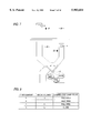
FIGS. 13 to 16 show conventional cool air wind passage structures. FIG. 13 is an appearance view of a conventional freezer-equipped refrigerator. FIG. 14 is a transparent perspective view showing a cool air wind structure of the conventional freezer-equipped refrigerator. As seen from FIG. 13, a freezer-equipped refrigerator 1 includes a refrigerating chamber 2 and freezing chambers 3 located below the refrigerating chamber 2. As shown in FIG. 14, the freezing chamber 3 incorporates a heat exchanger 4 and a fan 5 for circulating cool air located above the fan 5. The cool wind blown off from the fan 5 is branched into several areas. It blows off into the refrigerating chamber 2 as follows. It is taken in from an inlet 6, passes a duct 8 via an opening/closing damper 7 and blows off toward respective shelves from cool air blow-off openings 9. The blown off cool wind cools food or others in the refrigerating chamber 2 and drawn into an inhalation inlet 10. The cool wind further passes a return wind passage 11 to return to the lower part of the heat exchanger 4. Then, the cool wind is cooled again by the heat exchanger 4 and sent to the refrigerating chamber 2 and the like, and such circulation is repeated. Reference numeral 12 represents an element for detecting the temperature within the refrigerating chamber. FIG. 15 shows a control substrate 80 for controlling whether or not the circulation of cool wind should be carried out. FIG. 16 is a flowchart of a control of the circulation of cool wind. When the element 12 detects that the temperature of the refrigerating chamber 2 is higher than a setting value, the fan 5 rotates and the damper 7 opens so that cool wind is supplied to the respective shelves of the refrigerating chamber 2. Incidentally, in this case, it is assumed that a compressor for supplying refrigerant to the heat exchanger is rotating. When the temperature of the refrigerating chamber 2 detected by the element 12 is lower than the setting value, the damper 7 is closed. The fan 5, in accordance with the temperature of other chambers, continues to rotate or stops. By the repetition of such an operation, the temperature of the refrigerating chamber 2 is controlled so as to be constant.
One example of the conventional technique is disclosed in Japanese Patent Examined Application Hei. 7-11379.
Owing to the structure and control described above, the conventional freezer-equipped refrigerator has the following problems. If the chamber in a uniform temperature zone are sectioned by plural shelves or boxes, the temperature difference between the temperature of the element 12 and the sectioned places is increased. Accordingly, it is difficult to maintain the temperature of the refrigerating chamber at a predetermined temperature. Additionally, when the door of the refrigerating chamber 2 is opened, the temperature of the refrigerating chamber 2 increases. However, the temperature does not increase uniformly, and the temperature of an upper zone is increased. If the setting value is lowered in order to suppress such a phenomenon, inversely the temperature of the lowest section becomes lower than the setting value.
SUMMARY OF THE INVENTION
It is an object of the present invention to provide a freezer-equipped refrigerator with no variation in the temperature in a refrigerating chamber or a freezing chamber and good cooling performance.
A freezer-equipped refrigerator according to the present invention comprises: a refrigerating chamber; a freezing chamber; a plurality of sections formed within at least one of the refrigerating chamber and the freezing chamber, a setting temperature of the sections being substantially equal; temperature detecting means provided in each of the sections, for detecting a temperature of each section; a plurality of cool air supply ducts each having at least one cool air blow-off opening for supplying the cool air to each of the sections, the number of the cool air supply ducts being equal to the number of the temperature detecting means or the sections; opening/closing means for opening/closing an inlet for sucking the cool air into the cool air supply duct; and control means for controlling the open/close of the opening/closing means.
According to the present invention, the temperature of a plurality of sections formed in the refrigerating chamber or a freezing chamber can be uniform.
BRIEF DESCRIPTION OF THE DRAWINGS
In the accompanying drawings:
FIG. 1 is a general view of a freezer-equipped refrigerator;
FIG. 2 is a perspective view showing the cool wind circulating wind passage of a freezer-equipped refrigerator according to the first embodiment according to the present invention;
FIG. 3 is a schematic view of a control substrate for controlling whether the circulation of cool wind should be effected in a freezer-equipped refrigerator according to the first embodiment;
FIG. 4 is a control flowchart for controlling whether the circulation of cool wind should be effected in a freezer-equipped refrigerator according to the first embodiment;
FIG. 5 is a perspective view showing the cool wind circulating wind passage of a freezer-equipped refrigerator according to the first embodiment according to the present invention;
FIG. 6 is a table showing the relationship between each of the detected values of elements of a freezer-equipped refrigerator and open/close of each damper;
FIG. 7 is a schematic view of a control substrate for controlling whether the circulation of cool wind should be effected in a freezer-equipped refrigerator according to the third embodiment;
FIG. 8 is a view showing the relationship between the detected values and the standing point of a wind adjusting damper in a freezer-equipped refrigerator according to the third embodiment;
FIG. 9 is a perspective view showing the cool wind circulating passage in a freezer-equipped refrigerator according to the third embodiment;
FIG. 10 is a view showing the relationship between the detected values and the standing point of a wind adjusting damper in a freezer-equipped refrigerator according to the third embodiment;
FIGS. 11A and 11B are perspective views showing the cool wind circulating passage in a freezer-equipped refrigerator according to the fourth embodiment;
FIG. 12 is a perspective view showing the control wind circulating passage in a freezer-equipped refrigerator according to the fifth embodiment;
FIG. 13 is an appearance view of the conventional freezer-equipped refrigerator;
FIG. 14 is a perspective view of a cool air passage structure of the conventional freezer-equipped refrigerator;
FIG. 15 is a schematic view showing the control substrate 80 for controlling whether or not the circulation of cool air should be carried out in a conventional freezer-equipped refrigerator; and
FIG. 16 is a control flowchart for controlling whether or not the circulation of cool air should be carried out in a conventional freezer-equipped refrigerator.
PREFERRED EMBODIMENTS OF THE INVENTION
Preferred embodiments of the present invention will be described as follows referring to the accompanying drawings.
Embodiment 1
FIG. 1 is a perspective view showing a cool wind circulating passage of a freezer-equipped refrigerator according to the embodiment of the present invention. FIG. 2 is an enlarged view of the main part in FIG. 1. In FIG. 1, the freezer-equipped refrigerator 1 includes a refrigerating chamber 2 including two sections 23 and 26 (see, FIG. 2) having setting temperature of 0-10° and a freezing chamber 3 located below the refrigerating chamber 2. As shown in FIG. 2, the refrigerating chamber 2 is divided into the sections 23 and 26 by a partition plate 91. This partition plate may be a plate-like plate, a net-like plate or the like. However, it is possible to omit the partition plate 91 in this embodiment. As shown in FIG. 1, the freezing chamber 3 incorporates a heat exchanger 4 and a fan 5 for circulating cool air located above the heat exchanger 4. The cool wind blown off from the fan 5 is branched into several areas. It blows off into the refrigerating chamber 2 as follows. It is taken in from inlet 6, passes a box 90 in which a wind passage may be provided to communicate with each damper of a twin damper 20 or a base plate may be installed, and reaches a twin damper 20 which is a damper portion having a plurality of dampers. An UP damper 20A which is one of the plural opening/closing inlets serves to open/close an upper section duct 21 whereas an LR damper 20B which is also one of the plural closing opening/closing inlets serves to open/close a lower section duct 22. An upper section 23 is provided with a first temperature detecting element 24 which is one of temperature detecting elements whereas a lower section 26 is provided with a second temperature detecting element 25 which is also one of the temperature detecting elements. The upper section duct 21 and lower section duct 22 are provided with cool air blow-off openings 9 at the intermediate position and distal positions of tubes, which blow off the cool wind. The blown-off cool wind cools the food and others within the refrigerating chamber 2 and is drawn into an inhalation opening 10. The cool wind further passes a return wind passage 11 to return to the lower part of the heat exchanger 4. Then, the cool wind is rid of heat again by the heat exchanger 4 and sent to the refrigerating chamber 2 and others. Such circulation is repeated.
As shown in FIG. 2, in this embodiment, the refrigerating chamber 2 is divided to an upper section 23 and a lower section 26 by a separating plate 91. However, the refrigerating chamber 2 may be divided into three or more sections. The separating plate may be a plate-shaped plate, a net-shaped plate or the like. Furthermore, for example, one of the sections may be a closed type box.
The temperature control within the refrigerating chamber will be explained. FIG. 3 is a schematic view of a control substrate 80 for controlling whether or not the above cool wind circulation should be carried out. FIG. 4 is a flowchart of the controlling operation. In FIG. 4, when a power source is turned on, a compressor turns ON (S1), a fan turns ON (S2), and an UP damper and LR damper close (S3). If the temperatures detected by the respective first and second temperature detecting elements 24, 25 are higher than setting values, respectively (S4, S6), the fan 5 rotates and the opening/closing dampers (UP damper 20A and LR damper 20B) open (S5, S7) to lower the temperatures to the setting values. When the temperatures at the respective elements become lower than the setting values, respectively, the corresponding opening/closing dampers close.
As described above, in the freezer-equipped refrigerator according this embodiment, since a temperature detecting element is arranged within each of the sections having substantially equal setting temperatures, and the cool wind blown off from each of the ducts dedicated to the individual sections is locally controlled in accordance with the detected temperature. For this reason, the temperatures with the respective sections can be made uniform with high accuracy so that the freshness of food can be maintained for a long time. Even if "high burden" food at high temperatures are put locally or only within a certain section, the remaining sections are prevented from being cooled excessively so that the food therein can be cooled to prescribed temperatures. Further, since there is provided the twin damper which is a damper portion having a plurality of dampers, even if either damper suffers a breakdown, complete impossibility of cooling does not occur. In this embodiment, although an upper section and lower section are used as individual sections, they may be further divided in some sections.
Embodiment 2
The second embodiment is different from the first embodiment in the structure of ducts succeeding to the opening/closing dampers and the controlling method. FIG. 5 is a perspective view showing the cool wind circulating wind passage of the freezer-equipped refrigerator according to the second embodiment. A first duct 30 communicating with the one damper 20A of the twin damper 20 has cool wind blow-off openings 9 provided at the lower section 26 and upper section 23. On the other hand, a second duct 31 communicating with the other damper 20B of the twin damper 20 has the cool wind blow-off opening 9 provided at only the upper section 23. The first temperature detecting element 24 is arranged in the upper section whereas the second temperature detecting element 25 is arranged in the lower section 25. The coupling manner of the above elements with the control substrate 80 is the same as in the first embodiment.
An explanation will be given of the operation of the freezer-equipped refrigerator according to the second embodiment. FIG. 6 is a table showing the relationship between the temperatures at the temperature detecting elements and the open/close in each of the dampers of the twin damper 20. For example, if the temperature at the first element 25 is higher than a setting value ("H" in the table), that at the second element 25 is higher than a setting value ("H" in the table) and the absolute value the difference between the values detected by the first elements 24 and 25 is larger than a prescribed value ("h" in the table), both dampers of the twin damper 20 open to supply the cool wind. On the several conditions, if the absolute value of the difference between the values read by the elements is smaller than the prescribed value ("l" in the table), only the damper 20A opens. The operation described above applies to the case where the temperature of the upper section 23 is higher than that of the lower section 26. On the other hand, if the temperature of the lower section 26 is higher than that of the upper section 23, the cool wind blow-off opening 9 of the second duct 31 is arranged on the lower section 26 so that the relationship of the open/close of the dampers as shown in FIG. 6 can be applied. In this case, when either damper opens, the fan 5 rotates, and when both dampers close, the fan 5 is controlled in accordance with the temperature in the other sections.
As described above, in accordance with this embodiment, in a normal state, the upper section 23 and lower section 26 are cooled by the damper 20A, and only under a certain condition (the temperature at the first element 24 is higher than that at the second element 25 by a prescribed value or more), the damper 20B opens. For this reason, the temperature difference between the upper section 23 and the lower section 26 can be minimized. In addition, even if either damper suffers a breakdown, complete impossibility of cooling does not occur. Namely, the cooling by only the damper 20B permits the lower section to be convection-cooled slightly. In this embodiment, although an upper section and lower section are used as individual sections, they may be further divided in sections.
[0018]
Embodiment 3
Third embodiment according to the present invention is different from the second embodiment in the duct structure incorporating an opening/closing damper and the control method. FIG. 7 is a perspective view showing the cool wind circulating passage of the freezer-equipped refrigerator according to the third embodiment. In FIG. 7, reference numeral 40 represents a wind orientation adjusting damper which can adjust the opening/closing angle over 180° with high accuracy (using a two-phase exciting stepping motor as a driving source). The wind orientation adjusting damper has damper stationary points whose number is equal to the number of cool wind supply ducts communicating with the cool wind blow-off openings 9 which supply cool wind to the respective sections in the refrigerator 40 plus one point of wind passage closure. For example, where at the tip of the wind orientation damper, two ducts are located which communicate with the cool wind blow-off opening at the upper section 23 and lower section 26 , there are three stationary points. At the upper section 23, the first temperature detecting element 24 is provided in the upper section 23 whereas the second temperature detecting element 25 is provided in the lower section 26. The coupling manner of the above elements with the control substrate 80 is the same as in the second embodiment.
The operation of the freezer-equipped refrigerator according to the third embodiment will be explained.
FIG. 8 is a table showing the relationship between the temperatures at the temperature detecting elements and the stationary point of the wind adjusting damper 40. For example, if the temperature at the first element 24 is higher than a setting value ("H" in the table), that at the second element 25 is higher than a setting value ("H" in the table), the stationary point is fully open. If only the temperature at the first element 24 is higher than the setting temperature, the stationary point is half open. If both the temperatures at the first and second elements 24 and 25 are lower than the setting values, the stationary point is close.
For the reason described above, in the freezer-equipped refrigerator according to this embodiment, the temperature difference between the upper section 23 and the lower section 26 can be minimized and this can also be minimized using a single component (wind orientation damper 40). This reduces the production cost of the refrigerator. In this embodiment, although an upper section and lower section are used as individual sections, they may be further divided into several sections. Additionally, in FIG. 7, two ducts are located individually for the upper section 23 and lower section 26. But if ducts are located for the upper section 23 and for both upper and lower sections, the wind orientation damper 40 is opened or closed on the basis of the same manner as in the second embodiment, i.e., the differences between the detected temperatures of the temperature detecting elements 24 and 25 from their setting values, and the absolute value between the detected values of the respective elements.
FIG. 9 shows a duct structure which can also supply cool wind to only the duct communicating with the cool wind blow-off opening in the lower section 26. In this structure, the first and second temperature detecting elements 24 and 25, the damper 41 and the wind orientation damper 40 are used so that the full or half opening of the damper 41 and the opening or closing of the wind orientation adjusting damper 40 are controlled on the basis of the temperatures detected by the temperature detecting elements at the upper and lower sections of the freezing chamber. If both the temperatures detected by the elements 24 and 25 are higher than the setting values, the damper 41 is opened and the wind orientation damper 40 is located at both sections in FIG. 9 to supply cool wind to both ducts. If only the temperature detected by the one element is higher than the setting value, the damper 41 is opened and the wind orientation adjudging damper 40 is placed in one-side opened. Such a control intends to make the temperature uniform. FIG. 10 is a table showing a method of controlling the wind orientation adjusting damper 40 and the damper 41. For example, if the temperature at the element 25 is higher than a setting value ("H" in the table), that at the element 25 is higher than a setting value ("H" in the table) and the absolute value of the difference between the values detected by the elements 24 and 25 is larger than a prescribed value ("h" in the table), the damper 41 is open and the wind orientation adjusting damper 40 is located at an upper section position to supply cool wind to the upper section. Either upper section or lower section is determined by positioning of the origin of the damper 40.
Embodiment 4
The forth embodiment is different from the first embodiment in a duct structure. FIG. 11A is a perspective view of a freezer-equipped refrigerator according to the fourth embodiment. As shown in FIG. 11A, a refrigerator inside lamp 51 is fixed at the center of a partition plate 50 between an internal plate and the inside of the background of the refrigerator 2. The partition plate 50 is fixed to the internal plate of the refrigerator 2 by a screw 91. An upper duct 21 and a lower duct 22 are fixed between the partition plate and the internal plate. FIG. 11B is a perspective view of the cool wind circulating wind passage in which the partition plate 50 at the back of the freezing chamber 2 is removed for convenience of explanation. Since the cool wind supply ducts 21 and 22 are arranged on both sides on the back of the refrigerator, the refrigerator lamp 51 can be installed on the center of the back of the refrigerator 51. The cool air taken in from the cool air of a box 90 passes through the twin damper 20 and blows off to the cool air blow-off opening 9 of each duct. One of the wind passages of the ducts 20 and 22 is the front in the box 90 whereas the other thereof is the rear (back) in the box 90. For example, if the cool air supply ducts (upper section duct) 21 and the cool air supply ducts (lower section duct) 22 are provided on both sides of the back of the refrigerator, the lower ducts 22 separately blows up the cool air from the damper 20B towards both sides through this side (forward of the box 90) whereas the upper ducts 21 directly blows up the cool air toward both sides directly from the damper 20A. Inversely, the lower ducts 22 may blow up the cool air from the damper 20B towards both sides directly from the damper 20B whereas the upper ducts 21 may separately blow up the cool air toward both sides through this side (forward of the box 90) from the rear of the box 90. Because of such an arrangement of these wind passages, they do not overlap one another, and the ducts are not located on only the front side. Thus, the section within the refrigerator can be effectively used. Further, the cool wind can be supplied to the ducts each located on the upper and lower sections on both sides of the refrigerator lamp. The coupling manner of the above elements with the control substrate 80 and its operation are the same as in the second embodiment. Provision of the upper and lower ducts 21 and 22 on both sides further improves the accuracy of making uniform the temperatures at the respective points obtained in the first embodiment. The limitation to the width of the refrigerator lamp due to the increase in the number of ducts and wind passages can be reduced, thereby improving the design.
In FIG. 11B, a recess may be provided at the area on the center side of the refrigerator of the upper duct 21 where the cool wind blow-off opening 9 is not extended. This increases the illumination range of the lamp by the degree corresponding to the recess.
Embodiment 5
Fifth embodiment is different from the second embodiment in the duct structure. FIG. 12 is a perspective view of the cool wind circulating wind passage in which the partition plate 50 at the back of the freezing chamber 2 as shown in FIG. 11A removed for convenience of illustration. Since cool wind supply ducts 30 and 31 are arranged on both sides on the back of the refrigerator, the refrigerator lamp 51 can be centrally installed at the back of the refrigerator 51. The cool air taken in from the cool air inlet 6 of a box 90 passes through the twin damper 20 and is blown off to the cool air blow-off opening 9 of each duct. One of the wind passages of the ducts 20 and 22 is the front in the box 90 whereas the other thereof is the rear (back) in the box 90. For example, if the inside lamp 51 is centrally located at the back of the refrigerator 2, a pair of ducts 30 for blow-off for both upper and lower sections and another pair of ducts 31 for blow-off for only the upper section are installed on both sides of the refrigerator. The ducts 30 separately blow up the cool air from the damper 20B towards both sides through this side (forward of the box 90) whereas the ducts 31 directly blow up the cool air toward both sides directly from the damper 20A. Inversely, the ducts 30 may blow up the cool air towards both sides directly from the damper 20B whereas the duct 31 may separately blow up the cool air toward both sides through this side (forward of the box 90) from the rear of the box 90. Because of such an arrangement of these wind passages, the cool wind can be supplied to the pair of ducts for both sections and only the upper section located on both sides of the inside lamp. The coupling manner of the above elements with the control substrate 80 and its operation are the same as in the second embodiment. Provision of the pair of ducts 30 and the pair of ducts 31 on both sides further improves the accuracy of making uniform the temperatures at the respective points obtained in the second embodiment. The limitation to the width of the refrigerator lamp due to the increase in the number of ducts and wind passages can be reduced, thereby improving the design.
In FIG. 12, a recess may be provided at the area on the center side of the refrigerator of the upper duct 21 where the cool wind blow-off opening 9 is not extended. This increases the illumination range of the inside lamp by the degree corresponding to the recess.
Although the structure of the refrigerating chamber has been described in the above-described embodiments, the structure also can be applied to that of the freezing chamber to control the temperature therein.
A freezer-equipped refrigerator according to the present invention has a plurality of sections at substantially equal setting temperature zones partitioned within the freezer-equipped refrigerator and comprises temperature detecting means provided in each of said sections; a plurality of cool air supply ducts each having a cool air blow-off opening for supplying the cool air to each of said sections, the number of them being equal to that of said temperature detecting means or sections; a damper for opening or closing a sucking inlet of the cool air into said cool air supply duct; and control means for controlling the open/close of said damper by the temperature detected by said temperature detecting means. Because of such a structure, the temperature of each section can be made uniform.
Since a damper portion having a plurality of dampers is provided, the number of components can be reduced.
A freezer-equipped refrigerator according to the present invention has a plurality of sections at substantially equal setting temperature zones partitioned within the freezer-equipped refrigerator, and comprises temperature detecting means provided in each of said sections; a plurality of cool air supply ducts each having a cool air blow-off opening for supplying the cool air to each of said sections, the number of them being equal to that of said temperature detecting means or sections; a damper connected to said plurality of ducts, for opening or closing a sucking inlet for supplying cool air to said cool air supply ducts; and control means for controlling the amount of the cool air from the sucking inlet to said plurality of cool air supply ducts by the opening angle of said damper opened or closed. Because of such a structure, a plurality of dampers are replaced by a single wind orientation adjusting damper and the refrigerator can be fabricated at low cost.
Since the amount of cool air to each of the cool air supply ducts is determined by open/close controlling the damper in accordance with the value of the temperature detecting means provided for each of the sections, the temperature of each section can be made uniform with accuracy thereby to maintain the freshness of food for a longer time.
Since said cool air supply ducts are a combination of a duct for supplying the cool air to a plurality of sections and another duct for supply the cool air to a specific section, even if "high burden" food at high temperatures are put locally or only within a certain section, the remaining sections are prevented from being cooled excessively.
The damper is open/close controlled using a difference between each of values detected by the temperature detecting means and each of setting temperatures, or using these values and the absolute value of a difference between the detected values. For this reason, the temperature difference between the respective sections can be minimized.
A plurality of cool air supply ducts are preferably arranged on both sides of the back of the inside of a refrigerator so that the cool air supply ducts are located on both sides of the inside of the refrigerator to supply the cool air through the same damper. For this reason, the temperature within the refrigerator can be made uniform.
Preferably, cool air is supplied through a first cool air supply passage extending upward from the back of the inside of the refrigerator to one of a plurality of cool air supply ducts arranged on the one side whereas it is supplied from a sucking inlet through a second cool air supply passage located in front of said first cool air supply passage to the other cool air supply duct. For this reason, the wind passages do not overlap so that the section of the inside of the refrigerator can be used effectively.

Claims (13)

What is claimed is:
1. A freezer-equipped refrigerator comprising:
a refrigerating chamber;
a freezing chamber;
a plurality of sections formed within said refrigerating chamber, a setting temperature of said sections being substantially equal;
temperature detecting means provided in each of said sections, for detecting a temperature of each section;
a plurality of cool air supply ducts each having at least one cool air blow-off opening for supplying the cool air to each of said sections, the number of said cool air supply ducts being equal to the number of said temperature detecting means or said sections;
opening/closing means for opening/closing an inlet for sucking the cool air into said cool air supply ducts; and
control means for controlling the open/close of all of said opening/closing means as a function of temperatures detected by said temperature detecting means.
2. A freezer-equipped refrigerator according to claim 1, wherein said opening/closing means is a dumper.
3. A freezer-equipped refrigerator according to claim 2, wherein said opening/closing means is a dumper portion having a plurality of dampers.
4. A freezer-equipped refrigerator according to claim 1, wherein said opening/closing means is connected to said plurality of cool air supply ducts, and said control means controls said opening/closing means to control the amount of the cool air from the sucking inlet to said plurality of cool air supply ducts.
5. A freezer-equipped refrigerator according to claim 4, wherein said opening/closing means is a dumper, and said control means controls said dumper to control the amount of the cool air by the opening angle of said damper.
6. A freezer-equipped refrigerator according to claim 1, wherein the amount of cool air supplied to each of the cool air supply ducts is determined by controlling said opening/closing means based on the temperature detected by said temperature detecting means provided in each of said sections.
7. A freezer-equipped refrigerator according to claim 1, wherein said cool air supply ducts include a first duct for supplying the cool air to a plurality of sections and a second duct for supplying the cool air to a specific section.
8. A freezer-equipped refrigerator according to claim 6, wherein said control means controls said opening/closing means based on a difference between a setting temperature and the temperature detected by said temperature detecting means.
9. A freezer-equipped refrigerator according to claim 6, wherein said control means controls said opening/closing means further based on an absolute value of a difference between the temperatures of said sections detected by said temperature detecting means.
10. A freezer-equipped refrigerator according to claim 6, wherein a plurality of cool air supply ducts are arranged on both sides of the back of the inside of the refrigerator so that the cool air supply ducts are located on both sides of the inside of the refrigerator to supply the cool air through the same damper.
11. A freezer-equipped refrigerator according to claim 6, wherein cool air is supplied through a first cool air supply passage extending upward from the back of the inside of the refrigerator to one of said plurality of cool air supply ducts arranged on the one side whereas cool air is supplied from a sucking opening through a second cool air supply passage located in front of said first cool air supply passage to the other cool air supply duct.
12. A freezer-equipped refrigerator as recited in claim 1, wherein said refrigerator is located above said freezer.
13. A freezer-equipped refrigerator comprising:
a refrigerating chamber;
a freezing chamber arranged vertically with respect to the refrigerating chamber;
a vertically arranged plurality of sections formed within said refrigerating chamber, a setting temperature of said sections being substantially equal;
a temperature detector provided in each of said sections, for detecting a temperature of each section;
a plurality of cool air supply ducts connecting said freezing chamber with said sections of said refrigerating chamber, each of said cool air supply ducts having at least one cool air blow-off opening for supplying the cool air to one of said sections, the number of said cool air supply ducts being equal to the number of said sections;
a damper individually associated with each of said cool air supply ducts so as to selectively open and close an inlet for sucking the cool air into the respective cool air supply duct; and
control means for controlling the open/close of each of said dampers as a function of temperatures detected by said temperature detecting means.
US08/861,804 1996-08-08 1997-05-22 Freezer-equipped refrigerator Expired - Fee Related US5983654A (en)

Applications Claiming Priority (2)

Application Number Priority Date Filing Date Title
JP8-209648 1996-08-08
JP20964896A JP3399243B2 (en) 1996-08-08 1996-08-08 Freezer refrigerator

Publications (1)

Publication Number Publication Date
US5983654A true US5983654A (en) 1999-11-16

Family

ID=16576287

Family Applications (1)

Application Number Title Priority Date Filing Date
US08/861,804 Expired - Fee Related US5983654A (en) 1996-08-08 1997-05-22 Freezer-equipped refrigerator

Country Status (9)

Country Link
US (1) US5983654A (en)
EP (1) EP0828121B1 (en)
JP (1) JP3399243B2 (en)
KR (1) KR100232441B1 (en)
CN (1) CN1146714C (en)
DE (1) DE69724056D1 (en)
ID (1) ID17946A (en)
MY (1) MY132488A (en)
TW (1) TW333600B (en)

Cited By (21)

* Cited by examiner, † Cited by third party
Publication number Priority date Publication date Assignee Title
US6336339B1 (en) * 1999-06-09 2002-01-08 Lg Electronics Inc. Damper for refrigerators
US6343477B1 (en) * 1999-02-26 2002-02-05 Maytag Corporation Refrigerator food storage temperature control system
US6401481B2 (en) 1999-09-09 2002-06-11 Mitsubishi Denki Kabushiki Kaisha Refrigerator and method of operating refrigerator
US6463752B2 (en) 1999-02-26 2002-10-15 Maytag Corporation Refrigerator food storage compartment with quick chill feature
US6612116B2 (en) 1999-02-26 2003-09-02 Maytag Corporation Thermoelectric temperature controlled refrigerator food storage compartment
US20040050079A1 (en) * 2001-01-05 2004-03-18 Holmes John S. Refrigerator system and software architecture
US20040188935A1 (en) * 2003-03-31 2004-09-30 Lg Electronics Inc. Temperature control method for refrigerator
US20040216478A1 (en) * 2003-02-01 2004-11-04 Achim Melching Climatic device, and process for defrosting a heat exchanger in a climatic device
US20080000256A1 (en) * 2006-07-03 2008-01-03 Daewoo Electronics Corporation Cold air circulating apparatus for use in Kimchi refrigerator
US20080134712A1 (en) * 2006-12-11 2008-06-12 Whirlpool Corporation Device for controlling the refrigeration and humidity inside a drawer movable within a refrigerator
US20080195256A1 (en) * 2004-10-22 2008-08-14 Whirlpool Corporation Method for Controlling a Refrigerator Appliance
US20080196428A1 (en) * 2005-05-27 2008-08-21 Itw Industrial Components S.R.L. Con Unico Socio Device and Method For Controlling the Temperature Inside a Refrigerating Unit of a Combined Refrigerator-Freezer
US20080271475A1 (en) * 2007-01-29 2008-11-06 Wuesthoff Edward P Refrigerator having compartment capable of converting between refrigeration and freezing temperatures
US20100107678A1 (en) * 2007-04-03 2010-05-06 Chang Joon Kim Refrigerator and a control method for the same
US20140290302A1 (en) * 2013-04-01 2014-10-02 Lg Electronics Refrigerator
US20150033773A1 (en) * 2012-03-26 2015-02-05 Haier Group Corporation Refrigerator and operating method thereof
US9140477B2 (en) 2012-05-21 2015-09-22 Whirlpool Corporation Synchronous compartment temperature control and apparatus for refrigeration with reduced energy consumption
US9140478B2 (en) 2012-05-21 2015-09-22 Whirlpool Corporation Synchronous temperature rate control for refrigeration with reduced energy consumption
US9140479B2 (en) 2012-05-21 2015-09-22 Whirlpool Corporation Synchronous temperature rate control and apparatus for refrigeration with reduced energy consumption
US11085689B2 (en) * 2016-03-24 2021-08-10 Lg Electronics Inc. Control method for refrigerator
EP3538826B1 (en) * 2016-12-15 2022-04-06 Samsung Electronics Co., Ltd. Refrigerator

Families Citing this family (33)

* Cited by examiner, † Cited by third party
Publication number Priority date Publication date Assignee Title
DE19917974C2 (en) * 1999-04-21 2001-04-05 Aeg Hausgeraete Gmbh Refrigerator and / or freezer with a cold-generating component arranged in the interior
EP1199531B1 (en) * 2000-10-18 2005-08-24 Daewoo Electronics Corporation Cold air supplying device for refrigerator
CA2366622C (en) * 2001-08-31 2006-10-03 Lg Electronics Inc. Device for controlling cooling air supply of refrigerator
KR100873170B1 (en) * 2002-12-23 2008-12-10 엘지전자 주식회사 A system and control method for cool air division of refrigerator
JP2007168090A (en) * 2005-12-19 2007-07-05 Matsushita Electric Ind Co Ltd Screen printing equipment
FR2909262B1 (en) * 2006-12-05 2009-02-27 Const Isothrmiques Bontami C I FAST COOLING CELL DEVICE
JP4684279B2 (en) * 2007-11-02 2011-05-18 三菱電機株式会社 Freezer refrigerator
DE102008016926A1 (en) * 2008-01-30 2009-08-06 Liebherr-Hausgeräte Ochsenhausen GmbH Method for operating a refrigerator and / or freezer and operated by such a method refrigerator and / or freezer
ES2377620B1 (en) * 2009-04-07 2013-03-19 Fagor, S. Coop. REFRIGERATOR APPARATUS WITH COMPARTMENT WITH ADJUSTABLE TEMPERATURE.
JP5350321B2 (en) * 2010-05-24 2013-11-27 日立アプライアンス株式会社 refrigerator
CN101963423A (en) * 2010-08-06 2011-02-02 海信容声(广东)冰箱有限公司 Air duct system of frost-free refrigerator and control method thereof
JP5178808B2 (en) * 2010-11-04 2013-04-10 三菱電機株式会社 Freezer refrigerator
EP2527766A1 (en) * 2011-05-23 2012-11-28 Forster Küchen- & Kühltechnik AG Refrigerator
JP5553799B2 (en) * 2011-07-04 2014-07-16 三菱電機株式会社 refrigerator
JP5436522B2 (en) * 2011-11-25 2014-03-05 三菱電機株式会社 Freezer refrigerator
JP5909427B2 (en) * 2012-08-23 2016-04-26 日立アプライアンス株式会社 refrigerator
JP5909426B2 (en) * 2012-08-23 2016-04-26 日立アプライアンス株式会社 refrigerator
JP5836227B2 (en) * 2012-08-29 2015-12-24 日立アプライアンス株式会社 refrigerator
JP5941838B2 (en) * 2012-12-21 2016-06-29 日立アプライアンス株式会社 refrigerator
JP6223564B2 (en) * 2014-05-28 2017-11-01 三菱電機株式会社 refrigerator
CN104329863B (en) * 2014-09-25 2017-01-11 青岛海尔股份有限公司 Refrigerator and control method of refrigerator
CN105333673B (en) * 2015-11-27 2017-12-29 青岛海尔股份有限公司 Binary channels controls air door and has its ducting system and refrigerator
CN106152672A (en) * 2016-06-30 2016-11-23 青岛海尔股份有限公司 Room between a kind of refrigerator constant temperature
CN106196825A (en) * 2016-06-30 2016-12-07 青岛海尔股份有限公司 Room between a kind of refrigerator constant temperature
CN106839643A (en) * 2017-04-17 2017-06-13 安徽中科都菱商用电器股份有限公司 A kind of accurate temperature control device of medical refrigerator
JP6800083B2 (en) * 2017-04-21 2020-12-16 日立グローバルライフソリューションズ株式会社 refrigerator
CN112013605B (en) * 2017-04-21 2022-09-09 日立环球生活方案株式会社 Refrigerator with a door
DE102017128134A1 (en) * 2017-08-28 2019-02-28 Liebherr-Hausgeräte Lienz Gmbh Wine storage cabinet with two compartments
CN109425194A (en) * 2017-08-29 2019-03-05 合肥美的电冰箱有限公司 Wind cooling refrigerator temprature control method, device and refrigerator
JP6987156B2 (en) * 2018-01-19 2021-12-22 三菱電機株式会社 Refrigerator, refrigerator control method and program
CN109458787B (en) * 2018-11-05 2021-02-26 广州美的华凌冰箱有限公司 Refrigeration system and control method, device, equipment and storage medium thereof
CN114111162A (en) * 2020-08-31 2022-03-01 青岛海尔电冰箱有限公司 Refrigerator and control method thereof
CN114165965B (en) * 2020-09-10 2023-03-28 青岛海尔电冰箱有限公司 Refrigerator with a door

Citations (15)

* Cited by examiner, † Cited by third party
Publication number Priority date Publication date Assignee Title
US3048024A (en) * 1959-07-06 1962-08-07 Gen Motors Corp Refrigerating apparatus
US3070973A (en) * 1961-06-16 1963-01-01 Gen Motors Corp Refrigerating apparatus
US3233422A (en) * 1964-04-20 1966-02-08 Louis M Kobrin Refrigeration system
US3411312A (en) * 1967-09-01 1968-11-19 Whirlpool Co Refrigerator with convertible compartment
US3455119A (en) * 1968-02-16 1969-07-15 Gen Motors Corp Plural compartment high humidity domestic refrigerator
US3590594A (en) * 1969-05-13 1971-07-06 Golconda Corp Single evaporator multiple temperature refrigerator
US4009589A (en) * 1976-01-02 1977-03-01 General Electric Company Single evaporator, single fan combination refrigerator with independent temperature controls and method of adjustment
US4921164A (en) * 1988-09-14 1990-05-01 Kabushiki Kaisha Toshiba Central air conditioning system with damper and method for controlling the same
US5004149A (en) * 1989-01-24 1991-04-02 Kabushiki Kaisha Toshiba Central air conditioning system having compensating control function for total heat load in a plurality of rooms
US5025638A (en) * 1989-03-30 1991-06-25 Kabushiki Kaisha Toshiba Duct type air conditioner and method of controlling the same
US5076346A (en) * 1987-06-17 1991-12-31 Mitsubishi Denki Kabushiki Kaisha Air conditioner
JPH0593571A (en) * 1991-10-02 1993-04-16 Matsushita Refrig Co Ltd Refrigerator
US5209073A (en) * 1990-11-01 1993-05-11 Fisher & Paykel Limited Cooling device and method with multiple cooled chambers and multiple expansion means
US5359860A (en) * 1991-04-16 1994-11-01 Goldstar Co. Ltd. Method and apparatus for controlling a temperature in a refrigerating chamber of a refrigerator
JPH0711379A (en) * 1993-06-29 1995-01-13 Kawasaki Steel Corp Thin steel sheet excellent in impact resistance

Patent Citations (15)

* Cited by examiner, † Cited by third party
Publication number Priority date Publication date Assignee Title
US3048024A (en) * 1959-07-06 1962-08-07 Gen Motors Corp Refrigerating apparatus
US3070973A (en) * 1961-06-16 1963-01-01 Gen Motors Corp Refrigerating apparatus
US3233422A (en) * 1964-04-20 1966-02-08 Louis M Kobrin Refrigeration system
US3411312A (en) * 1967-09-01 1968-11-19 Whirlpool Co Refrigerator with convertible compartment
US3455119A (en) * 1968-02-16 1969-07-15 Gen Motors Corp Plural compartment high humidity domestic refrigerator
US3590594A (en) * 1969-05-13 1971-07-06 Golconda Corp Single evaporator multiple temperature refrigerator
US4009589A (en) * 1976-01-02 1977-03-01 General Electric Company Single evaporator, single fan combination refrigerator with independent temperature controls and method of adjustment
US5076346A (en) * 1987-06-17 1991-12-31 Mitsubishi Denki Kabushiki Kaisha Air conditioner
US4921164A (en) * 1988-09-14 1990-05-01 Kabushiki Kaisha Toshiba Central air conditioning system with damper and method for controlling the same
US5004149A (en) * 1989-01-24 1991-04-02 Kabushiki Kaisha Toshiba Central air conditioning system having compensating control function for total heat load in a plurality of rooms
US5025638A (en) * 1989-03-30 1991-06-25 Kabushiki Kaisha Toshiba Duct type air conditioner and method of controlling the same
US5209073A (en) * 1990-11-01 1993-05-11 Fisher & Paykel Limited Cooling device and method with multiple cooled chambers and multiple expansion means
US5359860A (en) * 1991-04-16 1994-11-01 Goldstar Co. Ltd. Method and apparatus for controlling a temperature in a refrigerating chamber of a refrigerator
JPH0593571A (en) * 1991-10-02 1993-04-16 Matsushita Refrig Co Ltd Refrigerator
JPH0711379A (en) * 1993-06-29 1995-01-13 Kawasaki Steel Corp Thin steel sheet excellent in impact resistance

Cited By (33)

* Cited by examiner, † Cited by third party
Publication number Priority date Publication date Assignee Title
US6463752B2 (en) 1999-02-26 2002-10-15 Maytag Corporation Refrigerator food storage compartment with quick chill feature
US6343477B1 (en) * 1999-02-26 2002-02-05 Maytag Corporation Refrigerator food storage temperature control system
US6612116B2 (en) 1999-02-26 2003-09-02 Maytag Corporation Thermoelectric temperature controlled refrigerator food storage compartment
US6336339B1 (en) * 1999-06-09 2002-01-08 Lg Electronics Inc. Damper for refrigerators
US6526766B1 (en) 1999-09-09 2003-03-04 Mitsubishi Denki Kabushiki Kaisha Refrigerator and method of operating refrigerator
US6405547B2 (en) 1999-09-09 2002-06-18 Mitsubishi Denki Kabushiki Kaisha Refrigerator and method of operating refrigerator
US6405544B2 (en) 1999-09-09 2002-06-18 Mitsubishi Denki Kabushiki Kaisha Refrigerator and method of operating refrigerator
US6401481B2 (en) 1999-09-09 2002-06-11 Mitsubishi Denki Kabushiki Kaisha Refrigerator and method of operating refrigerator
US20040050079A1 (en) * 2001-01-05 2004-03-18 Holmes John S. Refrigerator system and software architecture
US6802186B2 (en) * 2001-01-05 2004-10-12 General Electric Company Refrigerator system and software architecture
US20040216478A1 (en) * 2003-02-01 2004-11-04 Achim Melching Climatic device, and process for defrosting a heat exchanger in a climatic device
US20060070389A1 (en) * 2003-02-01 2006-04-06 Kendro Laboratory Products, Gmbh Climatic device, and process for defrosting a heat exchanger in a climatic device
US20040188935A1 (en) * 2003-03-31 2004-09-30 Lg Electronics Inc. Temperature control method for refrigerator
US6959559B2 (en) * 2003-03-31 2005-11-01 Lg Electronics, Inc. Temperature control method for refrigerator
US20080195256A1 (en) * 2004-10-22 2008-08-14 Whirlpool Corporation Method for Controlling a Refrigerator Appliance
US7757501B2 (en) * 2004-10-22 2010-07-20 Whirlpool Corporation Method for controlling a refrigerator appliance
US20080196428A1 (en) * 2005-05-27 2008-08-21 Itw Industrial Components S.R.L. Con Unico Socio Device and Method For Controlling the Temperature Inside a Refrigerating Unit of a Combined Refrigerator-Freezer
US8141375B2 (en) * 2005-05-27 2012-03-27 ITW Industrial Components S.R. L. Device and method for controlling the temperature inside a refrigerating unit of a combined refrigerator-freezer
US20080000256A1 (en) * 2006-07-03 2008-01-03 Daewoo Electronics Corporation Cold air circulating apparatus for use in Kimchi refrigerator
US8365549B2 (en) * 2006-12-11 2013-02-05 Whirlpool Corporation Device for controlling the refrigeration and humidity inside a drawer movable within a refrigerator
US20080134712A1 (en) * 2006-12-11 2008-06-12 Whirlpool Corporation Device for controlling the refrigeration and humidity inside a drawer movable within a refrigerator
US20080271475A1 (en) * 2007-01-29 2008-11-06 Wuesthoff Edward P Refrigerator having compartment capable of converting between refrigeration and freezing temperatures
US20100107678A1 (en) * 2007-04-03 2010-05-06 Chang Joon Kim Refrigerator and a control method for the same
US8904817B2 (en) * 2007-04-03 2014-12-09 Lg Electronics Inc. Refrigerator and a control method for the same
US20150033773A1 (en) * 2012-03-26 2015-02-05 Haier Group Corporation Refrigerator and operating method thereof
US9140478B2 (en) 2012-05-21 2015-09-22 Whirlpool Corporation Synchronous temperature rate control for refrigeration with reduced energy consumption
US9140477B2 (en) 2012-05-21 2015-09-22 Whirlpool Corporation Synchronous compartment temperature control and apparatus for refrigeration with reduced energy consumption
US9140479B2 (en) 2012-05-21 2015-09-22 Whirlpool Corporation Synchronous temperature rate control and apparatus for refrigeration with reduced energy consumption
US9810472B2 (en) 2012-05-21 2017-11-07 Whirlpool Corporation Synchronous temperature rate control for refrigeration with reduced energy consumption
US20140290302A1 (en) * 2013-04-01 2014-10-02 Lg Electronics Refrigerator
US9328951B2 (en) * 2013-04-01 2016-05-03 Lg Electronics Inc. Refrigerator
US11085689B2 (en) * 2016-03-24 2021-08-10 Lg Electronics Inc. Control method for refrigerator
EP3538826B1 (en) * 2016-12-15 2022-04-06 Samsung Electronics Co., Ltd. Refrigerator

Also Published As

Publication number Publication date
DE69724056D1 (en) 2003-09-18
KR19980018139A (en) 1998-06-05
JP3399243B2 (en) 2003-04-21
KR100232441B1 (en) 1999-12-01
ID17946A (en) 1998-02-12
EP0828121A2 (en) 1998-03-11
CN1146714C (en) 2004-04-21
CN1177718A (en) 1998-04-01
EP0828121B1 (en) 2003-08-13
TW333600B (en) 1998-06-11
EP0828121A3 (en) 1998-04-01
JPH1054642A (en) 1998-02-24
MY132488A (en) 2007-10-31

Similar Documents

Publication Publication Date Title
US5983654A (en) Freezer-equipped refrigerator
US5433086A (en) Refrigerator having independent temperature control of plural compartments
KR100208345B1 (en) Temperature control method and device of refrigerator
KR100533257B1 (en) A temperature control method for side by side refrigerator
JPH0743059A (en) Cold air circulation type refrigeraed showcase
KR100532903B1 (en) Refrigerator
JPH05141843A (en) Refrigerating and cooling cabinet
KR0136054Y1 (en) Cool air adjustment apparatus of a refrigerator
JPH1026457A (en) Refrigerator
US20060218962A1 (en) Airflow control system in refrigerators and freezers
JPH08105679A (en) Refrigerator
JPH0432683A (en) Open show case
KR100374563B1 (en) Apparatus for supplying cooling air in refrigerator
KR20030065943A (en) Air circulation system of side by side type Refrigerator
KR100340056B1 (en) Air circulation device of refrigerator
KR100221548B1 (en) Evaporator establishment structure of a refrigerator
JP3957863B2 (en) Freezer refrigerator
JP2000180016A (en) Refrigerator
KR100269377B1 (en) Refrigerator
KR0182124B1 (en) A refrigerator
JPH1123133A (en) Two-temperature type open showcase
KR19980020675A (en) Centralized cooling method of refrigerators and apparatus
JPS62268978A (en) Freezing refrigerator
JP2001343180A (en) Refrigerator
JP2004198061A (en) Refrigerator

Legal Events

Date Code Title Description
AS Assignment

Owner name: MITSUBISHI DENKI KABUSHIKI KAISHA, JAPAN

Free format text: ASSIGNMENT OF ASSIGNORS INTEREST;ASSIGNORS:YAMAMOTO, KAZU;HIRAOKA, TOSHIE;KATO, MUTSUMI;AND OTHERS;REEL/FRAME:009096/0750

Effective date: 19970509

AS Assignment

Owner name: MITSUBISHI DENKI KABUSHIKI KAISHA, JAPAN

Free format text: (ASSIGNMENT OF ASSIGNOR'S INTEREST) RE-RECORDED TO CORRECT THE RECORDATION DATE OF 04-06-98 TO 04-07-98 PREVIOUSLY RECORDED AT REEL 9096, FRAME 0750.;ASSIGNORS:YAMAMOTO, KAZU;HIRAOKA, TOSHIE;KATO, MUTSUMI;AND OTHERS;REEL/FRAME:010329/0017

Effective date: 19970509

FEPP Fee payment procedure

Free format text: PAYOR NUMBER ASSIGNED (ORIGINAL EVENT CODE: ASPN); ENTITY STATUS OF PATENT OWNER: LARGE ENTITY

FPAY Fee payment

Year of fee payment: 4

LAPS Lapse for failure to pay maintenance fees
STCH Information on status: patent discontinuation

Free format text: PATENT EXPIRED DUE TO NONPAYMENT OF MAINTENANCE FEES UNDER 37 CFR 1.362

FP Lapsed due to failure to pay maintenance fee

Effective date: 20071116