US5979527A - Heavy duty pneumatic radial tires with at least three bead portion rubbers - Google Patents
Heavy duty pneumatic radial tires with at least three bead portion rubbers Download PDFInfo
- Publication number
- US5979527A US5979527A US08/889,092 US88909297A US5979527A US 5979527 A US5979527 A US 5979527A US 88909297 A US88909297 A US 88909297A US 5979527 A US5979527 A US 5979527A
- Authority
- US
- United States
- Prior art keywords
- rubber
- bead portion
- rubber layer
- bead
- carcass ply
- Prior art date
- Legal status (The legal status is an assumption and is not a legal conclusion. Google has not performed a legal analysis and makes no representation as to the accuracy of the status listed.)
- Expired - Lifetime
Links
Images


Classifications
-
- B—PERFORMING OPERATIONS; TRANSPORTING
- B60—VEHICLES IN GENERAL
- B60C—VEHICLE TYRES; TYRE INFLATION; TYRE CHANGING; CONNECTING VALVES TO INFLATABLE ELASTIC BODIES IN GENERAL; DEVICES OR ARRANGEMENTS RELATED TO TYRES
- B60C9/00—Reinforcements or ply arrangement of pneumatic tyres
- B60C9/02—Carcasses
- B60C9/04—Carcasses the reinforcing cords of each carcass ply arranged in a substantially parallel relationship
- B60C9/08—Carcasses the reinforcing cords of each carcass ply arranged in a substantially parallel relationship the cords extend transversely from bead to bead, i.e. radial ply
-
- B—PERFORMING OPERATIONS; TRANSPORTING
- B60—VEHICLES IN GENERAL
- B60C—VEHICLE TYRES; TYRE INFLATION; TYRE CHANGING; CONNECTING VALVES TO INFLATABLE ELASTIC BODIES IN GENERAL; DEVICES OR ARRANGEMENTS RELATED TO TYRES
- B60C15/00—Tyre beads, e.g. ply turn-up or overlap
- B60C15/06—Flipper strips, fillers, or chafing strips and reinforcing layers for the construction of the bead
- B60C15/0603—Flipper strips, fillers, or chafing strips and reinforcing layers for the construction of the bead characterised by features of the bead filler or apex
- B60C15/0607—Flipper strips, fillers, or chafing strips and reinforcing layers for the construction of the bead characterised by features of the bead filler or apex comprising several parts, e.g. made of different rubbers
-
- B—PERFORMING OPERATIONS; TRANSPORTING
- B60—VEHICLES IN GENERAL
- B60C—VEHICLE TYRES; TYRE INFLATION; TYRE CHANGING; CONNECTING VALVES TO INFLATABLE ELASTIC BODIES IN GENERAL; DEVICES OR ARRANGEMENTS RELATED TO TYRES
- B60C15/00—Tyre beads, e.g. ply turn-up or overlap
- B60C15/06—Flipper strips, fillers, or chafing strips and reinforcing layers for the construction of the bead
- B60C15/0603—Flipper strips, fillers, or chafing strips and reinforcing layers for the construction of the bead characterised by features of the bead filler or apex
-
- B—PERFORMING OPERATIONS; TRANSPORTING
- B60—VEHICLES IN GENERAL
- B60C—VEHICLE TYRES; TYRE INFLATION; TYRE CHANGING; CONNECTING VALVES TO INFLATABLE ELASTIC BODIES IN GENERAL; DEVICES OR ARRANGEMENTS RELATED TO TYRES
- B60C15/00—Tyre beads, e.g. ply turn-up or overlap
- B60C15/06—Flipper strips, fillers, or chafing strips and reinforcing layers for the construction of the bead
- B60C2015/0614—Flipper strips, fillers, or chafing strips and reinforcing layers for the construction of the bead characterised by features of the chafer or clinch portion, i.e. the part of the bead contacting the rim
-
- Y—GENERAL TAGGING OF NEW TECHNOLOGICAL DEVELOPMENTS; GENERAL TAGGING OF CROSS-SECTIONAL TECHNOLOGIES SPANNING OVER SEVERAL SECTIONS OF THE IPC; TECHNICAL SUBJECTS COVERED BY FORMER USPC CROSS-REFERENCE ART COLLECTIONS [XRACs] AND DIGESTS
- Y10—TECHNICAL SUBJECTS COVERED BY FORMER USPC
- Y10T—TECHNICAL SUBJECTS COVERED BY FORMER US CLASSIFICATION
- Y10T152/00—Resilient tires and wheels
- Y10T152/10—Tires, resilient
- Y10T152/10495—Pneumatic tire or inner tube
- Y10T152/10819—Characterized by the structure of the bead portion of the tire
- Y10T152/10828—Chafer or sealing strips
-
- Y—GENERAL TAGGING OF NEW TECHNOLOGICAL DEVELOPMENTS; GENERAL TAGGING OF CROSS-SECTIONAL TECHNOLOGIES SPANNING OVER SEVERAL SECTIONS OF THE IPC; TECHNICAL SUBJECTS COVERED BY FORMER USPC CROSS-REFERENCE ART COLLECTIONS [XRACs] AND DIGESTS
- Y10—TECHNICAL SUBJECTS COVERED BY FORMER USPC
- Y10T—TECHNICAL SUBJECTS COVERED BY FORMER US CLASSIFICATION
- Y10T152/00—Resilient tires and wheels
- Y10T152/10—Tires, resilient
- Y10T152/10495—Pneumatic tire or inner tube
- Y10T152/10819—Characterized by the structure of the bead portion of the tire
- Y10T152/10837—Bead characterized by the radial extent of apex, flipper or chafer into tire sidewall
-
- Y—GENERAL TAGGING OF NEW TECHNOLOGICAL DEVELOPMENTS; GENERAL TAGGING OF CROSS-SECTIONAL TECHNOLOGIES SPANNING OVER SEVERAL SECTIONS OF THE IPC; TECHNICAL SUBJECTS COVERED BY FORMER USPC CROSS-REFERENCE ART COLLECTIONS [XRACs] AND DIGESTS
- Y10—TECHNICAL SUBJECTS COVERED BY FORMER USPC
- Y10T—TECHNICAL SUBJECTS COVERED BY FORMER US CLASSIFICATION
- Y10T152/00—Resilient tires and wheels
- Y10T152/10—Tires, resilient
- Y10T152/10495—Pneumatic tire or inner tube
- Y10T152/10819—Characterized by the structure of the bead portion of the tire
- Y10T152/10846—Bead characterized by the chemical composition and or physical properties of elastomers or the like
Definitions
- This invention relates to heavy duty pneumatic radial tires for use in heavy duty vehicles such as a truck, bus, industrial vehicle, construction vehicle and so on. More particularly it relates to a heavy duty pneumatic radial tire having an improved bead portion durability without increasing the weight of bead portion.
- Heavy duty pneumatic radial tires used in the above heavy duty vehicles are apt to cause problems in the bead portion, mainly separation failure because a force applied to the bead portion is large during running under loading.
- various techniques for improving bead portion durability mainly resistance to separation failure.
- the rigidity of the bead portion is further improved by an additional arrangement of a reinforcing member such as a nylon chafer, wire chafer or the like.
- the rigidity distribution is corrected by the rationalization of carcass line.
- These improving means are effective to control not only so-called falling deformation of the bead portion in the tire at a state of inflating under a given air pressure and at a state of loading under a given load but also the shearing deformation in the circumferential direction of the bead portion at positions corresponding to a stepping-in region and kicking-out region of the tread portion, so that they are widely adopted as a technique for contributing to the improvement of bead portion durability.
- the additional arrangement of the above reinforcing member naturally brings about not only the increase of weight but also rise of cost due to the increase of material cost and number of production steps, so that it is unsuitable in the existing severe price competition for the tire industry
- the other means not causing a weight increase such as the correction of the carcass line and the like certainly develop a given effect under relatively mild use conditions, but can not be adapted at the existing state of more severe use conditions and hence they are confirmed to insufficiently develop the given bead portion durability.
- an object of the invention to provide heavy duty pneumatic radial tires capable of developing sufficiently improved bead portion durability even under severe use conditions not dealing with the rationalization of the carcass line or the like without increasing the tire weight and the cost.
- a heavy duty pneumatic radial tire comprising a pair of bead portions, a pair of sidewall portions, a tread portion, a carcass ply extending between a pair of bead cores embedded in the bead portions and containing rubberized cords arranged in a radial direction of the tire and wound around each bead core from inside toward outside to form a turnup portion and a belt arranged on an outer periphery of the carcass ply, characterized in that at least three rubber layers of rubber material having different hardnesses exist in a zone ranging from the cords in the turnup portion of the carcass ply to an axially outer portion of the bead portion throughout a region of the bead portion corresponding to a line drawn normal to the axially outer portion of the bead portion in a contact area increased portion of the bead portion sandwiched between on the one hand, a contact end position of an axial outside surface of the bead portion on
- design rim “maximum air pressure” and “maximum loading ability” used herein are defined by technical terms described in TRA YEAR BOOK (1996), in which the design rim is determined in accordance with the kind and size of a tire and a ply rating by this YEAR BOOK, and the maximum loading ability is indicated by bold-faced loading ability value (lbs) described in TIRE LOAD LIMITS AT VARIOUS COLD INFLATION PRESSURES of the same YEAR BOOK, provided that when single wheel and dual wheel are described together, the value of the single wheel is adopted, and the maximum air pressure is an air pressure corresponding to the maximum loading ability.
- the term "the region of the bead portion corresponding to the line drawn normal to the axially outer portion of the bead portion in the contact area increased portion of the bead portion” used herein means a region of the bead portion passing through an arbitrary point on a curved face of the contact area increased portion and opposing to the contact area increased portion in a linear direction perpendicular to a tangential face of the contact area increased portion at this point.
- the region of the bead portion corresponding to the contact area increased portion in the radial direction is preferably a region sandwiched between a line drawn normal to the carcass ply from the contact end position of the axial outside surface of the bead portion on the rim flange when the tire is inflated at a maximum air pressure and a line drawn normal to the carcass play from the contact end position of from the axial outside surface of the bead portion on the rim flange under the above loading.
- the softest rubber layer is a sidewall rubber, or the hardest rubber layer is an insert rubber or a rubber chafer.
- FIG. 1 is a diagrammatically cross-sectional view of a main part of a first embodiment of the heavy duty pneumatic radial tire according to the invention
- FIG. 2 is a diagrammatically cross-sectional view of a main part of a second embodiment of the heavy duty pneumatic radial tire according to the invention.
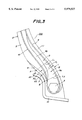
- FIG. 3 is a diagrammatically cross-sectional view of a main part of a third embodiment of the heavy duty pneumatic radial tire according to the invention.
- FIG. 4 is a diagrammatically cross-sectional view of a main part of the conventional heavy duty pneumatic radial tire.
- FIGS. 1-3 are diagrammatically cross-sectional views of main parts in various embodiments of the heavy duty pneumatic radial tire 100 (hereinafter referred to as tire or radial tire) assembled into a design rim 10 described in the aforementioned TRA YEAR BOOK, respectively.
- tire or radial tire assembled into a design rim 10 described in the aforementioned TRA YEAR BOOK, respectively.
- Each of these figures is a left-side cross-sectional view the tire from bead portion to sidewall portion in a radial direction of the tire when the tire 100 is inflated at a highest air pressure described in the above YEAR BOOK.
- the tire 100 comprises a pair of bead portions 1 and a pair of sidewall portions 2 (only one-side is shown in any case) and a tread portion (not shown), and is provided with a radial carcass ply 4 of rubberized cords, particularly steel cords extending between bead cores 3 embedded in the bead portions 1 to reinforce the bead portions 1, the sidewall portions 2 and the tread portion and a belt (not shown) reinforcing the tread portion on the outer periphery of the carcass ply 4 and comprised of plural cord cross layers, particularly steel cord cross layers according to usual practice.
- a radial carcass ply 4 of rubberized cords particularly steel cords extending between bead cores 3 embedded in the bead portions 1 to reinforce the bead portions 1, the sidewall portions 2 and the tread portion and a belt (not shown) reinforcing the tread portion on the outer periphery of the carcass ply 4 and comprised of plural cord cross layers, particularly steel cord cross layers according to usual practice
- the carcass ply 4 extends between a pair of the bead cores 3 and is wound around each of the bead cores 3 from inside toward outside to form a turnup portion 4t.
- the turnup portion 4t has a high turnup structure extending near to a maximum width of the tire.
- Rubber 5 constituting the sidewall portion 2 extends from each side end of the tread (not shown) down to a zone of each of the bead portions 1 and is overlapped with a rubber chafer 8 to connect to the bead portion 2.
- an outward end in the radial direction at an outside surface of the rubber chafer 8 extends over an outside edge of a flange 10f of a rim 10 from a viewpoint of the arrangement purpose.
- the contact end position of the outside surface of the bead portion 1 from the flange 10f of the rim 10 is shifted from a position B at only a state of inflating under the highest air pressure to a position A which increases the contact area between the outside surface of the bead portion 1 and the flange 10f.
- the term "contact end position” used herein means an outermost position of the bead portion 1 contacting with the flange 10f in the radial direction.
- the outside surface of the bead portion 1 sandwiched between the contact end position A and the contact end position B is called a contact area increased portion.
- This increased portion is not same as in a direction of the ground contact region along a circumferential line of the tread, so that the contact end position A is a position just under a load indicating a maximum fall-down deformation and near thereto and hence the contact area increased portion is determined by an unload state after the removal of the load.
- the behavior of the fall-down deformation of the bead portion 1 is typically shown by an arrow from the contact end position A, so that the top of the arrow in the fall-down deformation meets with a position Af on the flange 10f of the rim 10.
- At least three rubber layers of rubber material having different hardnesses exist in a zone R 0 ranging from cord, desirably steel cord (not shown) in the turnup portion 4t of the carcass ply 4 to the axial outside portion of the bead portion at a region R of the bead portion 1 corresponding to a direction of a normal line V L (arrow direction) drawn in the contact area increased portion of the bead portion from an arbitrary point P on the contact area increased portion between the bead portion 1 and the flange 10f of the rim 10 accompanied with the above fall-down deformation.
- the term "normal line V L" used herein means a straight line passing through an arbitrary point P on a curved face of the contact area increased portion (curved line in FIGS. 1-3) and perpendicular to a tangential face of the contact area increased portion at this point P (tangential line in FIGS. 1-3).
- the region R of the bead portion 1 is specified to a region sandwiched between a normal line L 1 drawn from the contact end position A of the outside surface of the bead portion 1 (outermost position in the radial direction) to the carcass ply 4 and a normal line L 2 drawn from the contact end position B of the outside surface of the bead portion (outermost position in the radial direction) to the carcass ply 4 and hence the zone R 0 ranging from the cords in the turnup portion 4t of the carcass ply 4 to the outside surface of the bead portion is located in the region R.
- the zone R 0 is naturally extended over a full circumference of the tire and at least three rubber layers of rubber material having different hardnesses exist in the zone R 0 , one of which layers is a coating rubber for the turnup portion 4t.
- a rubber layer arranged adjacent to the turnup portion 4t along its outside surface is a cushion rubber 6 in FIGS. 1 and 2 and a sidewall rubber 5 in FIG. 3. These rubber layers are required to be a softest rubber material at the zone R 0 . Furthermore, a rubber layer among one or more remaining rubber layers is arranged adjacent to the softest rubber layer along its outside surface and is an insert rubber 7 in FIG. 1 and a rubber chafer 8 made from a hardest rubber material in FIGS. 2 and 3.
- the softest rubber layer is required to have a 100% modulus of not more than 20 kgf/cm 2 , while the 100% modulus of the hardest rubber layer is required to be not less than 3 times that of the softest rubber layer. From these facts, it is naturally clear that the hardness and 100% modulus of the coating rubber for the carcass ply 4 are values between those of these softest and hardest rubber layers, respectively.
- the cushion rubber 6 is a rubber member developing the same stress mitigating function as a cushion rubber usually used in an end portion of the belt, while the insert rubber 7 is a rubber member usually disposed among plural constructional members.
- the bead portion 1 takes a rotating form around the bead core 3 as it is.
- the rubber layers existing in the zone R 0 are considerably compressed between the turnup portion 4t, more particularly the cords, i.e. steel cord of the turnup portion 4t and the flange 10f of the rim 10.
- Such a large compression strain creates a large flowing deformation in the rubber layers outward in the radial direction along the flange 10f, so that the rubber layers are subjected to a large shearing deformation.
- Such a shearing deformation is transmitted to the outside surface of the turnup portion 4t of the carcass ply 4.
- separation failure is created in a boundary between the cords, particularly steel cord of the turnup portion 4t and the coating rubber or in the vicinity of the cords.
- the softest rubber layer i.e. the cushion rubber 6 in FIGS. 1 and 2 and the sidewall rubber 5 in FIG. 2 is arranged adjacent to the turnup portion 4t along its outside surface, so that the shearing deformation transmitted from the flange 10f of the rim 10 in the fall-down deformation is absorbed by the softest rubber layer, whereby the shearing stress applied to the outside surface of the turnup portion 4t can largely be mitigated.
- the 100% modulus of the softest rubber layer should be not more than 20 kgf/cm 2 .
- the hardest rubber layer i.e. the insert rubber 7 in FIG. 1 and the rubber chafer 8 in FIGS. 2 and 3 is arranged adjacent to the softest rubber layer along its outside surface, whereby the flowing displacement of the rubber layer existing in the zone R 0 in the fall-down deformation can be decreased to mitigate the shearing stress applied to the outside surface of the turnup portion 4t.
- the rigidity of the bead portion 1 is lacking and the quantity of the fall-down deformation increases and hence the effect of the arrangement of the softest rubber layer is diminished and also the relative movement between the flange 10f and the rubber of the bead portion contacting with the flange through falling down increases to promote the wearing of rubber.
- the combination of the softest rubber layer and the hardest rubber layer is applied to the zone R 0 , whereby the shearing strain applied to the outside surface of the turnup portion 4t can advantageously be reduced while providing sufficient rigidity to the bead portion and the resistance to separation in the bead portion 1 can considerably be improved.
- the 100% modulus of the softest rubber layer exceeds 20 kgf/cm 2 , the shearing stress can not sufficiently be mitigated. From this point, it is desirable that the value of the 100% modulus is made small as far as possible.
- the 100% modulus of the hardest rubber layer is less than 3 times that of the softest rubber layer, the aforementioned drawbacks can not sufficiently be eliminated. From this point, the larger the ratio of 100% modulus of hardest rubber layer to softest rubber layer, the better the result.
- the three or more rubber layers of rubber material having different hardnesses in the zone R 0 are preferred to have a cross-sectional shape extending outward from the zone R 0 in the radial direction as shown in FIGS. 1-3.
- Numeral 9 is a stiffener, in which 9a is a hard stiffener and 9b is a soft stiffener, and numeral 11 is an innerliner, which are arranged according to the conventional structure and may particularly be selected to have optimum hardness and arrangement in connection with the hardest rubber layer and the softest rubber layer.
- Example 1 corresponds to FIG. 1 and Examples 2 and 3 correspond to FIG. 2 and Example 4 corresponds to FIG. 3.
- the softest rubber layer in Example 4 corresponds to the sidewall rubber 5.
- a tire 100A having a structure shown in FIG. 4 as a conventional example. In these tires, values of 100% modulus M100 (unit: kgf/cm 2 ) of rubber layers are shown in Table 1.
- the durability of the bead portion is evaluated by a drum test with respect to each of these tires.
- the test method and conditions are as follows:
- the tread rubber is cut out from the tread portion so as to surely create the problem of the bead portion prior to the occurrence of the belt separation.
- the tire is inflated under a highest air pressure of 7 kgf/cm 2 and placed on a drum rotating at a surface speed of 10 km/h under an initial loading of 51.5 ton (100% load corresponding to an approximately maximum load) and then a load is increased stepwise after the running for a given time.
- 51.5 ton 100% load corresponding to an approximately maximum load
- the invention can provide heavy duty pneumatic radial tires capable of advantageously improving the durability of the bead portion while maintaining the high productivity without requiring the arrangement of additional reinforcing members and increasing the tire weight.
Landscapes
- Engineering & Computer Science (AREA)
- Mechanical Engineering (AREA)
- Tires In General (AREA)
Applications Claiming Priority (2)
| Application Number | Priority Date | Filing Date | Title |
|---|---|---|---|
| JP17809796 | 1996-07-08 | ||
| JP8-178097 | 1996-07-08 |
Publications (1)
| Publication Number | Publication Date |
|---|---|
| US5979527A true US5979527A (en) | 1999-11-09 |
Family
ID=16042595
Family Applications (1)
| Application Number | Title | Priority Date | Filing Date |
|---|---|---|---|
| US08/889,092 Expired - Lifetime US5979527A (en) | 1996-07-08 | 1997-07-07 | Heavy duty pneumatic radial tires with at least three bead portion rubbers |
Country Status (3)
| Country | Link |
|---|---|
| US (1) | US5979527A (de) |
| EP (1) | EP0818331B1 (de) |
| ES (1) | ES2181997T3 (de) |
Cited By (10)
| Publication number | Priority date | Publication date | Assignee | Title |
|---|---|---|---|---|
| US6543504B2 (en) | 1998-12-24 | 2003-04-08 | Michelin Recherche Et Technique S.A. | Bead for a radial tire |
| US20060054259A1 (en) * | 2004-09-13 | 2006-03-16 | Sumitomo Rubber Industries, Ltd. | Pneumatic tire and manufacturing method of the same |
| US20080083479A1 (en) * | 2006-10-10 | 2008-04-10 | Giorgio Agostini | Tire with sidewall insert |
| US20090205766A1 (en) * | 2006-07-25 | 2009-08-20 | The Yokohama Rubber Co., Ltd. | Heavy-duty pneumatic tire |
| CN104669952A (zh) * | 2015-03-09 | 2015-06-03 | 山东玲珑轮胎股份有限公司 | 一种全钢子午线重载轮胎 |
| US9096100B2 (en) | 2012-11-12 | 2015-08-04 | The Goodyear Tire & Rubber Company | Tire with chafer and sidewall |
| JP2015160485A (ja) * | 2014-02-26 | 2015-09-07 | 住友ゴム工業株式会社 | 空気入りタイヤ |
| US9895938B2 (en) * | 2012-11-29 | 2018-02-20 | Compagnie Generale Des Etablissments Michelin | Tire bead for aircraft |
| US10052918B2 (en) * | 2013-11-27 | 2018-08-21 | The Goodyear Tire & Rubber Company | Tire with chafer and toeguard |
| CN109414966A (zh) * | 2016-07-13 | 2019-03-01 | 米其林集团总公司 | 具有减轻重量胎圈区域的轮胎 |
Families Citing this family (3)
| Publication number | Priority date | Publication date | Assignee | Title |
|---|---|---|---|---|
| DE102017209900A1 (de) * | 2017-06-13 | 2018-12-13 | Continental Reifen Deutschland Gmbh | Fahrzeugreifen |
| CN110799356B (zh) * | 2017-06-27 | 2021-11-30 | 米其林集团总公司 | 轻质轮胎 |
| FR3069193A1 (fr) * | 2017-07-19 | 2019-01-25 | Compagnie Generale Des Etablissements Michelin | Pneumatique allege |
Citations (10)
| Publication number | Priority date | Publication date | Assignee | Title |
|---|---|---|---|---|
| US4019551A (en) * | 1976-01-23 | 1977-04-26 | The Goodyear Tire & Rubber Company | Chipperless radial ply tire |
| US4941523A (en) * | 1989-02-23 | 1990-07-17 | The Goodyear Tire & Rubber Company | Pneumatic tire |
| US5048584A (en) * | 1988-12-22 | 1991-09-17 | Bridgestone Corporation | Radial tire for constuction vehicle |
| FR2670160A1 (fr) * | 1990-12-10 | 1992-06-12 | Sumitomo Rubber Ind | Pneumatique pour vitesses elevees et lourdes charges. |
| JPH04306108A (ja) * | 1991-04-01 | 1992-10-28 | Bridgestone Corp | 空気入りラジアルタイヤ |
| US5196077A (en) * | 1986-10-27 | 1993-03-23 | The Yokohama Rubber Co., Ltd. | Pneumatic radial tire |
| US5236031A (en) * | 1990-11-20 | 1993-08-17 | Bridgestone Corporation | Pneumatic radial tires for construction vehicle |
| EP0659596A2 (de) * | 1993-12-21 | 1995-06-28 | Bridgestone Corporation | Radialer Reifen für Flugzeuge |
| EP0749855A1 (de) * | 1995-06-19 | 1996-12-27 | Sumitomo Rubber Industries Limited | Radial LKW-Reifen |
| EP0798139A2 (de) * | 1996-03-26 | 1997-10-01 | Sumitomo Rubber Industries Limited | Luftreifen |
-
1997
- 1997-07-04 EP EP19970304886 patent/EP0818331B1/de not_active Expired - Lifetime
- 1997-07-04 ES ES97304886T patent/ES2181997T3/es not_active Expired - Lifetime
- 1997-07-07 US US08/889,092 patent/US5979527A/en not_active Expired - Lifetime
Patent Citations (10)
| Publication number | Priority date | Publication date | Assignee | Title |
|---|---|---|---|---|
| US4019551A (en) * | 1976-01-23 | 1977-04-26 | The Goodyear Tire & Rubber Company | Chipperless radial ply tire |
| US5196077A (en) * | 1986-10-27 | 1993-03-23 | The Yokohama Rubber Co., Ltd. | Pneumatic radial tire |
| US5048584A (en) * | 1988-12-22 | 1991-09-17 | Bridgestone Corporation | Radial tire for constuction vehicle |
| US4941523A (en) * | 1989-02-23 | 1990-07-17 | The Goodyear Tire & Rubber Company | Pneumatic tire |
| US5236031A (en) * | 1990-11-20 | 1993-08-17 | Bridgestone Corporation | Pneumatic radial tires for construction vehicle |
| FR2670160A1 (fr) * | 1990-12-10 | 1992-06-12 | Sumitomo Rubber Ind | Pneumatique pour vitesses elevees et lourdes charges. |
| JPH04306108A (ja) * | 1991-04-01 | 1992-10-28 | Bridgestone Corp | 空気入りラジアルタイヤ |
| EP0659596A2 (de) * | 1993-12-21 | 1995-06-28 | Bridgestone Corporation | Radialer Reifen für Flugzeuge |
| EP0749855A1 (de) * | 1995-06-19 | 1996-12-27 | Sumitomo Rubber Industries Limited | Radial LKW-Reifen |
| EP0798139A2 (de) * | 1996-03-26 | 1997-10-01 | Sumitomo Rubber Industries Limited | Luftreifen |
Non-Patent Citations (8)
| Title |
|---|
| Abstract of JP A 3 42310, Feb. 22, 1991, Japan (Bridgestone Corp). * |
| Abstract of JP A 7 137507, May 30, 1995, Japan (Bridgestone Corp). * |
| Abstract of JP A 7 144517, Jun. 6, 1995, Japan (Bridgestone Corp.). * |
| Abstract of JP-A-3-42310, Feb. 22, 1991, Japan (Bridgestone Corp). |
| Abstract of JP-A-7-137507, May 30, 1995, Japan (Bridgestone Corp). |
| Abstract of JP-A-7-144517, Jun. 6, 1995, Japan (Bridgestone Corp.). |
| Patent Abstracts of Japan, vol. 017, No. 123 (M 1380), Mar. 15, 1993 & JP 04 306108 A, Oct. 28, 1992 (Abstract). * |
| Patent Abstracts of Japan, vol. 017, No. 123 (M-1380), Mar. 15, 1993 & JP 04 306108 A, Oct. 28, 1992 (Abstract). |
Cited By (15)
| Publication number | Priority date | Publication date | Assignee | Title |
|---|---|---|---|---|
| US6543504B2 (en) | 1998-12-24 | 2003-04-08 | Michelin Recherche Et Technique S.A. | Bead for a radial tire |
| RU2235025C2 (ru) * | 1998-12-24 | 2004-08-27 | Сосьете Де Текнолоджи Мишлен | Борт радиальной пневматической шины |
| US20060054259A1 (en) * | 2004-09-13 | 2006-03-16 | Sumitomo Rubber Industries, Ltd. | Pneumatic tire and manufacturing method of the same |
| US7628190B2 (en) * | 2004-09-13 | 2009-12-08 | Sumitomo Rubber Industries, Ltd. | Pneumatic tire and manufacturing method of the same |
| US8267136B2 (en) * | 2006-07-25 | 2012-09-18 | The Yokohama Rubber Co., Ltd. | Heavy-duty pneumatic tire |
| US20090205766A1 (en) * | 2006-07-25 | 2009-08-20 | The Yokohama Rubber Co., Ltd. | Heavy-duty pneumatic tire |
| US7694708B2 (en) | 2006-10-10 | 2010-04-13 | The Goodyear Tire & Rubber Company | Tire with sidewall insert |
| US20080083479A1 (en) * | 2006-10-10 | 2008-04-10 | Giorgio Agostini | Tire with sidewall insert |
| US9096100B2 (en) | 2012-11-12 | 2015-08-04 | The Goodyear Tire & Rubber Company | Tire with chafer and sidewall |
| US9895938B2 (en) * | 2012-11-29 | 2018-02-20 | Compagnie Generale Des Etablissments Michelin | Tire bead for aircraft |
| US10052918B2 (en) * | 2013-11-27 | 2018-08-21 | The Goodyear Tire & Rubber Company | Tire with chafer and toeguard |
| US10239363B2 (en) | 2013-11-27 | 2019-03-26 | The Goodyear Tire & Rubber Company | Tire with chafer and toeguard |
| JP2015160485A (ja) * | 2014-02-26 | 2015-09-07 | 住友ゴム工業株式会社 | 空気入りタイヤ |
| CN104669952A (zh) * | 2015-03-09 | 2015-06-03 | 山东玲珑轮胎股份有限公司 | 一种全钢子午线重载轮胎 |
| CN109414966A (zh) * | 2016-07-13 | 2019-03-01 | 米其林集团总公司 | 具有减轻重量胎圈区域的轮胎 |
Also Published As
| Publication number | Publication date |
|---|---|
| ES2181997T3 (es) | 2003-03-01 |
| EP0818331A3 (de) | 1998-12-09 |
| EP0818331B1 (de) | 2002-09-25 |
| EP0818331A2 (de) | 1998-01-14 |
Similar Documents
| Publication | Publication Date | Title |
|---|---|---|
| US6109320A (en) | Heavy duty radial tire with specified bead core inside diameter | |
| US5876527A (en) | Pneumatic radial tires with rubber filler composed of three rubber stocks | |
| EP0206679B1 (de) | Wulstverstärkung für LKW-Reifen | |
| US4917166A (en) | Pneumatic radial tire having an improved durability in bead section | |
| US5080158A (en) | Bead reinforcement for a radial tire for heavy duty | |
| AU647984B2 (en) | Pneumatic radial tires | |
| US5979527A (en) | Heavy duty pneumatic radial tires with at least three bead portion rubbers | |
| EP0736400B1 (de) | Schwerlastradialluftreifen | |
| US6701988B2 (en) | Pneumatic radial tires | |
| US5979528A (en) | Heavy duty pneumatic radial tires with bead portion reinforcing layer having two different cord inclination angles | |
| US6823914B2 (en) | Heavy duty pneumatic radial tires with organic fiber cord bead reinforcing layer | |
| EP0881102A2 (de) | LKW-Reifen | |
| EP0698513B1 (de) | Radialer Luftreifen | |
| US6145560A (en) | Heavy duty pneumatic radial tires with specified belt cushion rubbers | |
| EP0882607A2 (de) | Radialer Luftreifen | |
| US5060707A (en) | Off-the-road heavy duty pneumatic radial tires with sidewall reinforcing layers | |
| US5733395A (en) | Pneumatic tire for two-wheeled vehicle with hard rubber layer outside carcass turn-up | |
| JP4021521B2 (ja) | 重荷重用空気入りラジアルタイヤ | |
| US6615889B1 (en) | Heavy duty radial tire | |
| JPH1024712A (ja) | 重荷重用空気入りラジアルタイヤ | |
| JP2001001716A (ja) | 重荷重用空気入りラジアルタイヤ | |
| EP0867312B1 (de) | Radiale Luftreifen für grosse Fahrzeuge | |
| EP1013477B1 (de) | Luftreifen | |
| US20020007892A1 (en) | High bead ratio tire |
Legal Events
| Date | Code | Title | Description |
|---|---|---|---|
| AS | Assignment |
Owner name: BRIDGESTONE CORPORATION, JAPAN Free format text: ASSIGNMENT OF ASSIGNORS INTEREST;ASSIGNORS:KOBAYASHI, YASUHIKO;NAGAI, YUICHI;REEL/FRAME:008678/0770 Effective date: 19970625 |
|
| STCF | Information on status: patent grant |
Free format text: PATENTED CASE |
|
| FEPP | Fee payment procedure |
Free format text: PAYOR NUMBER ASSIGNED (ORIGINAL EVENT CODE: ASPN); ENTITY STATUS OF PATENT OWNER: LARGE ENTITY |
|
| FPAY | Fee payment |
Year of fee payment: 4 |
|
| FPAY | Fee payment |
Year of fee payment: 8 |
|
| FPAY | Fee payment |
Year of fee payment: 12 |