US5979087A - Electric motor having electrostatic shield arrangement - Google Patents
Electric motor having electrostatic shield arrangement Download PDFInfo
- Publication number
- US5979087A US5979087A US09/008,345 US834598A US5979087A US 5979087 A US5979087 A US 5979087A US 834598 A US834598 A US 834598A US 5979087 A US5979087 A US 5979087A
- Authority
- US
- United States
- Prior art keywords
- conductive
- stator
- magnetically permeable
- permeable core
- coilheads
- Prior art date
- Legal status (The legal status is an assumption and is not a legal conclusion. Google has not performed a legal analysis and makes no representation as to the accuracy of the status listed.)
- Expired - Lifetime
Links
Images


Classifications
-
- H—ELECTRICITY
- H02—GENERATION; CONVERSION OR DISTRIBUTION OF ELECTRIC POWER
- H02K—DYNAMO-ELECTRIC MACHINES
- H02K3/00—Details of windings
- H02K3/46—Fastening of windings on the stator or rotor structure
- H02K3/48—Fastening of windings on the stator or rotor structure in slots
- H02K3/487—Slot-closing devices
-
- H—ELECTRICITY
- H02—GENERATION; CONVERSION OR DISTRIBUTION OF ELECTRIC POWER
- H02K—DYNAMO-ELECTRIC MACHINES
- H02K11/00—Structural association of dynamo-electric machines with electric components or with devices for shielding, monitoring or protection
- H02K11/01—Structural association of dynamo-electric machines with electric components or with devices for shielding, monitoring or protection for shielding from electromagnetic fields, i.e. structural association with shields
- H02K11/014—Shields associated with stationary parts, e.g. stator cores
-
- H—ELECTRICITY
- H02—GENERATION; CONVERSION OR DISTRIBUTION OF ELECTRIC POWER
- H02K—DYNAMO-ELECTRIC MACHINES
- H02K17/00—Asynchronous induction motors; Asynchronous induction generators
- H02K17/02—Asynchronous induction motors
- H02K17/16—Asynchronous induction motors having rotors with internally short-circuited windings, e.g. cage rotors
Definitions
- the present invention relates generally to the art of electric motors and other electromechanical machines. More particularly, the invention relates to improved electrostatic shield arrangements for use in an electromechanical machine.
- each bearing assembly is supported by a portion of the housing known as the "end bell.”
- the end bell is located at one axial end of the housing, and defines a hole through which the rotatable shaft freely extends.
- the present invention recognizes and addresses the foregoing disadvantages, and others of prior art constructions and methods. Accordingly, it is an object of the present invention to provide an electromechanical machine having a novel electrostatic shield arrangement.
- an electromechanical machine comprising a movable rotor and a fixed stator.
- the stator has conductive windings located in a plurality of parallel, axially-extending winding slots defined in a magnetically permeable core.
- Elongate top sticks are situated in the winding slots of the stator to interpose the conductive windings and the rotor.
- the elongate top sticks have a conductive portion insulated from the conductive windings to form an electrostatic shield arrangement.
- the top stick includes an insulative portion situated between the conductive portion thereof and the conductive winding of the respective slot.
- the top stick's conductive portion is in electrical communication with the magnetically permeable core.
- the top sticks may be constructed as a composite element having an insulative layer and a conductive layer.
- the conductive layer may be formed by a metallic paint, such as a copper paint.
- the elongate top sticks may be configured having a generally U-shaped configuration. In this case, the conductive layer may be in electrical communication with the magnetically permeable core by direct contact with inside walls of the winding slot.
- the stator will further comprise first and second coilheads located at opposite axial ends of the magnetically permeable core.
- first and second electrostatic coilhead shields are preferably situated adjacent respective inside surfaces of the coilheads.
- the electrostatic coilhead shields may comprise respective sheet assemblies, each having an insulative portion and a conductive portion. The insulative portion is situated between the conductive portion and the coilheads.
- an electromechanical machine comprising a fixed stator having conductive windings located in a plurality of parallel, axially-extending winding slots defined about an inner surface of a magnetically permeable core.
- the stator further comprises first and second coilheads located at opposite axial ends of the magnetically permeable core.
- a movable rotor is located radially inward of the stator.
- First and second electrostatic coilhead shields are also provided, situated adjacent respective inside surfaces of the respective coilheads. It will often be desirable to further provide electrostatic slot shields located in each of the winding slots.
- the electrostatic coilhead shields each comprise sheet assemblies having an insulative portion and a conductive portion.
- the insulative portion is situated between the conductive portion and the respective coilhead.
- the sheet assemblies may each include at least one finger portion extending into a winding slot of the magnetically permeable core.
- each of the sheet assemblies may comprise a plurality of sheet members electrically connected together to form a continuously conductive annular coilhead shield.
- the conductive portion of each sheet assembly may be electrically connected to the magnetically permeable core via the finger portion thereof.
- an electromechanical machine comprising a movable rotor and a fixed stator.
- the fixed stator includes a magnetically permeable core defining a plurality of parallel, axially-extending winding slots defined about an inner surface thereof.
- Multiphase conductive windings are located in the winding slots.
- phase insulating and electrostatic shielding material is situated between respective phases of the multiphase conductive windings.
- the phase insulating and electrostatic shielding material comprises a composite sheet material having an inner conductive layer and outer insulative layers.
- the inner conductive layer is preferably electrically connected to ground.
- FIG. 1 is an elevational view of an electric motor showing the motor housing partially cut away to reveal various internal components therein;
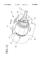
- FIG. 2 is a perspective view of the stator and a portion of the motor shaft, with the motor housing being shown in phantom;
- FIG. 3 is an enlarged, partial cross sectional view as taken along line 3--3 of FIG. 2;
- FIG. 4 is an enlarged, partial cross sectional view as taken along line 4--4 of FIG. 3;
- FIG. 5 is an assembly view showing the positioning of various elements with respect to the winding slots defined in the magnetically permeable core
- FIG. 5A is an enlarged view, partially cut away to show the construction of elongate top sticks used to form the illustrated electrostatic slot shield;
- FIG. 5B is an enlarged view, partially cut away to show the construction of sheet members used in the illustrated coilhead shield
- FIG. 6 is a plan view showing the relative position of coilhead shields at opposite axial ends of the magnetically permeable core
- FIG. 7 is an enlarged partial cross sectional view taken at one end of the magnetically permeable core to illustrate the use of phase insulating and electrostatic shielding material according to the present invention
- FIG. 8 is a perspective view of a preferred phase insulating and electrostatic shielding material according to the present invention, with layers cut away to show the construction thereof;
- FIG. 9 is an enlarged perspective view showing further details of the arrangement of FIG. 7.
- an electric motor 10 constructed in accordance with the present invention has a rotatable shaft 12 extending along a central axis.
- the internal components of motor 10 are enclosed by a housing including a main housing portion 14.
- One or more eyebolts 16 may be provided to facilitate lifting of motor 10.
- Main housing portion 14 defines an appropriate base 18 on which motor 10 will rest during use.
- the housing of motor 10 further includes end portions, such as end bell 20, located at respective axial sides of main housing portion 14.
- the end portions may be attached to main housing portion 14 by any appropriate means, such as by bolts.
- each end portion will maintain a respective bearing assembly, such as bearing assembly 22, to facilitate rotation of shaft 12.
- Shaft 12 continues through bearing assembly 22 and beyond end bell 20 for connection to other equipment.
- the opposite end of shaft 12 carries a fan 24, located within shroud 26. Due to the configuration of shroud 26, rotation of fan 24 causes cooling air to circulate around various cooling fins 28 defined on the exterior of main housing portion 14.
- motor 10 Inside of its housing, motor 10 includes a stator 30 that remains fixed during operation.
- Stator 30 includes a magnetically permeable core 32 preferably comprising a plurality of relatively thin laminations arranged in a stack.
- longitudinal windings are located in parallel, axially-extending slots defined about the inside surface of core 32 to provide a flow path for flux-generating current. The windings turn at respective coilheads 36 and 38 to return along a parallel slot.
- a rotor 40 secured to shaft 12, desirably rotates based on the electromagnetic interaction between it and stator 30.
- motor 10 is an induction motor, wherein rotor 40 is constructed as a "squirrel cage" in a known manner.
- a plurality of radial vanes, such as vanes 42, may be provided at the periphery of the rotor ends to circulate cooling air inside the motor housing.
- the present invention provides an electrostatic shield arrangement interposed between rotor 40 and the conductive windings of stator 30.
- the electrostatic shield arrangement provides a conductive path to ground for charge that could otherwise collect on rotor 40.
- the electrostatic shield arrangement is constructed so that the conductive path will be well-insulated from the conductive windings of stator 30. This is particularly advantageous in inverter-driven motor applications due to the high switching voltages that can be developed.
- the electrostatic shield arrangement is configured to provide continuous shielding from coilhead 36 across the slot windings to coilhead 38.
- motor 10 includes a pair of annular coilhead shields 44 and 46 located adjacent the respective inner surfaces of coilheads 36 and 38.
- coilhead shields 44 and 46 are each constructed as a sheet assembly providing a continuously conductive annulus insulated from the coilhead windings.
- conductive windings 34 each comprise a plurality of individual conductors situated in winding slots 48. Although the conductors are individually insulated, an insulative slot liner 50 is preferably located in each slot to further prevent the possibility of grounding to core 32.
- a top liner 52 known as a "top stick,” is located at the "top” of each slot and extends substantially the entire axial length of core 32.
- top stick 52 has a generally U-shaped configuration comprising an insulative layer 54 of a suitable polymeric material.
- insulative layer 54 of a suitable polymeric material.
- Prior art top sticks have often been made from Nomex or Mylar, which are also believed to be suitable materials for insulative layer 54.
- top stick 52 further includes a conductive layer 56 on its outer surface.
- insulative layer 54 thus separates conductive windings 34 from conductive layer 56.
- the legs of top stick 52 are preferably located outside of slot liner 50 so that conductive layer 56 will contact the inside walls of slot 48.
- the electrostatic shield will be grounded to core 32. Because core 32 is already grounded, there is generally no need to provide a conductive layer on the inner surface of core 32 between adjacent winding slots.
- each shield is constructed as a sheet assembly comprising a plurality of individual sheet members 58.
- Each sheet member 58 comprises a main shield portion 60 having one or more finger portions 62 extending therefrom. Finger portions 62 are adapted to extend into slots 48 above top sticks 52.
- sheet members 58 comprise an insulative layer 64 having a conductive layer 66 on one surface thereof.
- Each sheet member 58 is oriented such that conductive layer 66 will be radially inward (i.e., closer to shaft 12) with respect to insulative layer 64. Insulative layer 64 will thus serve to separate conductive layer 66 from the coilhead windings.
- the sheet members are grounded to core 32 by the direct contact of conductive layer 66, as disposed on finger portions 62, with the inside walls of slot 48.
- the respective conductive layers of each sheet member in one of the coilhead shields will be connected together to provide electrical continuity about the shield annulus.
- adjacent ends of main portions 60 are turned back and interconnected, as indicated at 68.
- the conductive layers 66 will be in direct contact with one another.
- This configuration also ensures that the conductive layer will always remain separated from coilhead windings by an insulative layer.
- the folded portion is maintained in position against an overlying conductive layer by friction.
- the present invention contemplates, however, that it may be desirable to adhere the two conductive layers, such as by solder or a conductive adhesive.
- FIGS. 7 through 9 illustrate an alternative electrostatic shield arrangement constructed in accordance with the present invention.
- each slot 48 may carry windings for more than one phase.
- FIGS. 7 and 9 show a multiphase motor configuration wherein each winding slot carries two distinct windings 34a and 34b, respectively located at the "top" and "bottom” of the slot.
- each winding slot 48 has a slot liner 50 and a nonshielding top stick 72 of the prior art.
- phase windings in a multiphase motor have often been separated by insulating phase paper, such as "H-paper.”
- an element 74 may be provided which serves the function of prior art phase paper while simultaneously providing an electrostatic shield.
- each element 74 has a shape like that of typical H-paper, including two end portions 76 and 78 interconnected by elongate finger portions 80.
- Elongate finger portions 80 extend axially within slots 48 to separate phase windings therein, while end portions 76 and 78 separate phase windings at the respective coilheads.
- element 74 is constructed as a three-layer composite.
- a conductive layer 82 of copper or other nonmagnetic material is sandwiched between two insulative layers 84 and 86.
- Conductive tabs may extend from end portion 76 as shown to permit grounding wires to be easily connected.
- Insulative layers in the various embodiments discussed above may be formed of Nomex or other suitable insulative material.
- the conductive layers are preferably formed of a nonmagnetic material to prevent adverse effects on the magnetic properties of the machine.
- the conductive layers may be applied to their associated insulative layer by spraying or brushing, such as by application of a conductive paint. Paints suitable for this purpose which are copper filled and conductive when dried in a film are available from Spraylat Corporation of Chicago, Ill. In a known application, such paints have been used in the past to treat fan screens to reduce static buildup.
- the present invention provides electromechanical machines having novel electrostatic shield arrangements. While preferred embodiments of the invention have been shown and described, modifications and variations may be made thereto by those of ordinary skill in the art without departing from the spirit and scope of the present invention, which is more particularly set forth in the appended claims. In addition, it should be understood that aspects of the various embodiments may be interchanged both in whole or in part. Furthermore, those of ordinary skill in the art will appreciate that the foregoing description is by way of example only, and is not intended to be limitative of the invention so further described in such appended claims.
Landscapes
- Engineering & Computer Science (AREA)
- Power Engineering (AREA)
- Physics & Mathematics (AREA)
- Electromagnetism (AREA)
- Insulation, Fastening Of Motor, Generator Windings (AREA)
Abstract
Description
Claims (5)
Priority Applications (1)
| Application Number | Priority Date | Filing Date | Title |
|---|---|---|---|
| US09/008,345 US5979087A (en) | 1998-01-16 | 1998-01-16 | Electric motor having electrostatic shield arrangement |
Applications Claiming Priority (1)
| Application Number | Priority Date | Filing Date | Title |
|---|---|---|---|
| US09/008,345 US5979087A (en) | 1998-01-16 | 1998-01-16 | Electric motor having electrostatic shield arrangement |
Publications (1)
| Publication Number | Publication Date |
|---|---|
| US5979087A true US5979087A (en) | 1999-11-09 |
Family
ID=21731097
Family Applications (1)
| Application Number | Title | Priority Date | Filing Date |
|---|---|---|---|
| US09/008,345 Expired - Lifetime US5979087A (en) | 1998-01-16 | 1998-01-16 | Electric motor having electrostatic shield arrangement |
Country Status (1)
| Country | Link |
|---|---|
| US (1) | US5979087A (en) |
Cited By (28)
| Publication number | Priority date | Publication date | Assignee | Title |
|---|---|---|---|---|
| US20030129855A1 (en) * | 2001-12-21 | 2003-07-10 | Douglas Richard E. | Current collector assembly and method |
| US6720692B2 (en) | 1998-01-16 | 2004-04-13 | Reliance Electric Technologies, Llc | Electric motor having electrostatic shield arrangement |
| US20060013009A1 (en) * | 2004-07-19 | 2006-01-19 | Falco Stephen F Jr | Recessed to spot light converter |
| US20060145560A1 (en) * | 2002-10-21 | 2006-07-06 | Abb Oy | Arrangement for protecting an electric machine |
| US20100007235A1 (en) * | 2008-07-11 | 2010-01-14 | Ludovic Chretien | Systems and methods for shielding an electric machine |
| US20120153767A1 (en) * | 2010-12-20 | 2012-06-21 | Zhongshan Broad-Ocean Motor Co., Ltd. | Mounting structure for slot paper in a motor stator |
| EP2541740A1 (en) | 2011-06-29 | 2013-01-02 | Grundfos Holding A/S | Stator |
| DE102011078428A1 (en) * | 2011-06-30 | 2013-01-03 | Siemens Aktiengesellschaft | Electric machine with bearing voltage suppression |
| CN103036328A (en) * | 2011-09-29 | 2013-04-10 | 华锐风电科技(集团)股份有限公司 | Stator, manufacture method and motor |
| US8558422B2 (en) | 2011-03-31 | 2013-10-15 | Caterpillar Inc. | Uniform contained cooling for stator |
| US20140319959A1 (en) * | 2013-04-24 | 2014-10-30 | GM Global Technology Operations LLC | Insulation system for an electric machine |
| EP2822157A1 (en) * | 2013-07-05 | 2015-01-07 | Siemens Aktiengesellschaft | Reduction of bearing currents in a wind turbine generator |
| FR3008562A1 (en) * | 2013-07-10 | 2015-01-16 | Bosch Gmbh Robert | ELECTRIC MACHINE AND METHOD FOR PRODUCING AND / OR MANAGING SUCH AN ELECTRIC MACHINE |
| US20150371768A1 (en) * | 2014-06-20 | 2015-12-24 | Apple Inc. | Methods for forming shield materials onto inductive coils |
| CN105720723A (en) * | 2014-12-12 | 2016-06-29 | 奥迪股份公司 | Motor vehicle motors with EMV measures |
| WO2016091360A3 (en) * | 2014-12-10 | 2016-08-04 | Audi Ag | Electric machine and motor vehicle |
| US20160294241A1 (en) * | 2015-03-30 | 2016-10-06 | Hyundai Motor Company | Motor unit having insulation member |
| WO2017028993A1 (en) * | 2015-08-14 | 2017-02-23 | Robert Bosch Gmbh | Stator of an electric machine |
| EP3185405A1 (en) * | 2015-12-23 | 2017-06-28 | Grundfos Holding A/S | Electric motor |
| US20170256998A1 (en) * | 2016-03-07 | 2017-09-07 | Volkswagen Aktiengesellschaft | Stator of an electric machine and slot liner cage for a stator |
| US9812935B2 (en) | 2014-08-19 | 2017-11-07 | Regal Beloit America, Inc. | Electric machine, conductor guide and associated method |
| US9852844B2 (en) | 2014-03-24 | 2017-12-26 | Apple Inc. | Magnetic shielding in inductive power transfer |
| US10327326B2 (en) | 2017-08-17 | 2019-06-18 | Apple Inc. | Electronic device with encapsulated circuit assembly having an integrated metal layer |
| US10498280B1 (en) | 2016-08-25 | 2019-12-03 | Apple Inc. | Electric motor with shielded phase windings |
| EP3213396B1 (en) * | 2014-10-29 | 2020-04-29 | Robert Bosch GmbH | Electrical asynchronous machine |
| US10699842B2 (en) | 2014-09-02 | 2020-06-30 | Apple Inc. | Magnetically doped adhesive for enhancing magnetic coupling |
| EP4436014A1 (en) * | 2023-03-22 | 2024-09-25 | Hyundai Mobis Co., Ltd. | Insulation structure |
| US20250219512A1 (en) * | 2023-12-28 | 2025-07-03 | Canoo Technologies Inc. | Electro-magnetic shield to prevent bearing and/or gearbox damage due to shaft induced voltage in electric motors |
Citations (16)
| Publication number | Priority date | Publication date | Assignee | Title |
|---|---|---|---|---|
| US2573126A (en) * | 1948-01-21 | 1951-10-30 | Smith Corp A O | Submersible electric motor |
| GB963880A (en) * | 1960-06-17 | 1964-07-15 | English Electric Co Ltd | Improvements relating to dynamo-electric machines |
| US3283187A (en) * | 1964-03-12 | 1966-11-01 | Franklin Electric Co Inc | Electric motor with a laminated bore liner |
| US3633056A (en) * | 1970-07-21 | 1972-01-04 | Gen Electric | Stator slot and winding arrangements |
| US3633057A (en) * | 1970-07-21 | 1972-01-04 | Gen Electric | Stator having improved winding distribution |
| US4160926A (en) * | 1975-06-20 | 1979-07-10 | The Epoxylite Corporation | Materials and impregnating compositions for insulating electric machines |
| US4246505A (en) * | 1979-03-19 | 1981-01-20 | Hitachi, Ltd. | Rotor with salient poles and shield plates between the poles |
| US4308476A (en) * | 1974-12-04 | 1981-12-29 | Bbc Brown Boveri & Co. Ltd. | Bar windings for electrical machines |
| JPS61185034A (en) * | 1985-02-08 | 1986-08-18 | Mitsubishi Electric Corp | Molded underwater motor |
| US4780635A (en) * | 1987-02-27 | 1988-10-25 | General Electric Company | Dynamo-electric machine lamination construction |
| US4949001A (en) * | 1989-07-21 | 1990-08-14 | Campbell Steven R | Partial discharge detection method and apparatus |
| US5175396A (en) * | 1990-12-14 | 1992-12-29 | Westinghouse Electric Corp. | Low-electric stress insulating wall for high voltage coils having roebeled strands |
| US5341561A (en) * | 1990-07-03 | 1994-08-30 | Isovolta Osterreichische Isolierstoffwerke Aktiengesellschaft | Process for producing the electric insulation of electric machine windings |
| US5661353A (en) * | 1995-05-25 | 1997-08-26 | Allen-Bradley Company, Inc. | Electrostatic shield for AC motor |
| US5821652A (en) * | 1996-08-28 | 1998-10-13 | Marathon Electric Manufacturing Corporation | Dynamoelectric machines with shaft voltage prevention method and structure |
| US5821649A (en) * | 1995-08-18 | 1998-10-13 | Magnetek, Inc. | Electrostatic shielding system for reduction of bearing currents in electric motors |
-
1998
- 1998-01-16 US US09/008,345 patent/US5979087A/en not_active Expired - Lifetime
Patent Citations (16)
| Publication number | Priority date | Publication date | Assignee | Title |
|---|---|---|---|---|
| US2573126A (en) * | 1948-01-21 | 1951-10-30 | Smith Corp A O | Submersible electric motor |
| GB963880A (en) * | 1960-06-17 | 1964-07-15 | English Electric Co Ltd | Improvements relating to dynamo-electric machines |
| US3283187A (en) * | 1964-03-12 | 1966-11-01 | Franklin Electric Co Inc | Electric motor with a laminated bore liner |
| US3633056A (en) * | 1970-07-21 | 1972-01-04 | Gen Electric | Stator slot and winding arrangements |
| US3633057A (en) * | 1970-07-21 | 1972-01-04 | Gen Electric | Stator having improved winding distribution |
| US4308476A (en) * | 1974-12-04 | 1981-12-29 | Bbc Brown Boveri & Co. Ltd. | Bar windings for electrical machines |
| US4160926A (en) * | 1975-06-20 | 1979-07-10 | The Epoxylite Corporation | Materials and impregnating compositions for insulating electric machines |
| US4246505A (en) * | 1979-03-19 | 1981-01-20 | Hitachi, Ltd. | Rotor with salient poles and shield plates between the poles |
| JPS61185034A (en) * | 1985-02-08 | 1986-08-18 | Mitsubishi Electric Corp | Molded underwater motor |
| US4780635A (en) * | 1987-02-27 | 1988-10-25 | General Electric Company | Dynamo-electric machine lamination construction |
| US4949001A (en) * | 1989-07-21 | 1990-08-14 | Campbell Steven R | Partial discharge detection method and apparatus |
| US5341561A (en) * | 1990-07-03 | 1994-08-30 | Isovolta Osterreichische Isolierstoffwerke Aktiengesellschaft | Process for producing the electric insulation of electric machine windings |
| US5175396A (en) * | 1990-12-14 | 1992-12-29 | Westinghouse Electric Corp. | Low-electric stress insulating wall for high voltage coils having roebeled strands |
| US5661353A (en) * | 1995-05-25 | 1997-08-26 | Allen-Bradley Company, Inc. | Electrostatic shield for AC motor |
| US5821649A (en) * | 1995-08-18 | 1998-10-13 | Magnetek, Inc. | Electrostatic shielding system for reduction of bearing currents in electric motors |
| US5821652A (en) * | 1996-08-28 | 1998-10-13 | Marathon Electric Manufacturing Corporation | Dynamoelectric machines with shaft voltage prevention method and structure |
Non-Patent Citations (2)
| Title |
|---|
| U.S. Ser. No. 008,043, Bell, filed Jan. 16, 1998, (pending). * |
| U.S. Ser. No. 113,490, Bell et al., filed Jul. 10, 1998, (pending) * |
Cited By (46)
| Publication number | Priority date | Publication date | Assignee | Title |
|---|---|---|---|---|
| US6720692B2 (en) | 1998-01-16 | 2004-04-13 | Reliance Electric Technologies, Llc | Electric motor having electrostatic shield arrangement |
| US20030129855A1 (en) * | 2001-12-21 | 2003-07-10 | Douglas Richard E. | Current collector assembly and method |
| US20060145560A1 (en) * | 2002-10-21 | 2006-07-06 | Abb Oy | Arrangement for protecting an electric machine |
| US7250700B2 (en) * | 2002-10-21 | 2007-07-31 | Abb Oy | Arrangement for protecting an electric machine |
| US20060013009A1 (en) * | 2004-07-19 | 2006-01-19 | Falco Stephen F Jr | Recessed to spot light converter |
| US7952251B2 (en) | 2008-07-11 | 2011-05-31 | Rbc Manufacturing Corporation | Systems and methods for shielding an electric machine |
| US20100007235A1 (en) * | 2008-07-11 | 2010-01-14 | Ludovic Chretien | Systems and methods for shielding an electric machine |
| US8853913B2 (en) * | 2010-12-20 | 2014-10-07 | Zhongshan Broad-Ocean Motor Co., Ltd. | Mounting structure for slot paper in a motor stator |
| US20120153767A1 (en) * | 2010-12-20 | 2012-06-21 | Zhongshan Broad-Ocean Motor Co., Ltd. | Mounting structure for slot paper in a motor stator |
| US8558422B2 (en) | 2011-03-31 | 2013-10-15 | Caterpillar Inc. | Uniform contained cooling for stator |
| EP2541740A1 (en) | 2011-06-29 | 2013-01-02 | Grundfos Holding A/S | Stator |
| CN102857004A (en) * | 2011-06-29 | 2013-01-02 | 格兰富控股联合股份公司 | Stator |
| US20130002060A1 (en) * | 2011-06-29 | 2013-01-03 | Grundfos Holding A/S | Stator |
| CN102857004B (en) * | 2011-06-29 | 2016-12-21 | 格兰富控股联合股份公司 | Stator |
| DE102011078428A1 (en) * | 2011-06-30 | 2013-01-03 | Siemens Aktiengesellschaft | Electric machine with bearing voltage suppression |
| CN103036328A (en) * | 2011-09-29 | 2013-04-10 | 华锐风电科技(集团)股份有限公司 | Stator, manufacture method and motor |
| US20140319959A1 (en) * | 2013-04-24 | 2014-10-30 | GM Global Technology Operations LLC | Insulation system for an electric machine |
| US9444298B2 (en) * | 2013-04-24 | 2016-09-13 | GM Global Technology Operations LLC | Insulation system for an electric machine |
| EP2822157A1 (en) * | 2013-07-05 | 2015-01-07 | Siemens Aktiengesellschaft | Reduction of bearing currents in a wind turbine generator |
| FR3008562A1 (en) * | 2013-07-10 | 2015-01-16 | Bosch Gmbh Robert | ELECTRIC MACHINE AND METHOD FOR PRODUCING AND / OR MANAGING SUCH AN ELECTRIC MACHINE |
| US9852844B2 (en) | 2014-03-24 | 2017-12-26 | Apple Inc. | Magnetic shielding in inductive power transfer |
| US9460846B2 (en) * | 2014-06-20 | 2016-10-04 | Apple Inc. | Methods for forming shield materials onto inductive coils |
| US20150371768A1 (en) * | 2014-06-20 | 2015-12-24 | Apple Inc. | Methods for forming shield materials onto inductive coils |
| US10043612B2 (en) | 2014-06-20 | 2018-08-07 | Apple Inc. | Methods for forming shield materials onto inductive coils |
| US9812935B2 (en) | 2014-08-19 | 2017-11-07 | Regal Beloit America, Inc. | Electric machine, conductor guide and associated method |
| US10699842B2 (en) | 2014-09-02 | 2020-06-30 | Apple Inc. | Magnetically doped adhesive for enhancing magnetic coupling |
| EP3213396B1 (en) * | 2014-10-29 | 2020-04-29 | Robert Bosch GmbH | Electrical asynchronous machine |
| US10547226B2 (en) * | 2014-12-10 | 2020-01-28 | Audi Ag | Electric machine and motor vehicle |
| WO2016091360A3 (en) * | 2014-12-10 | 2016-08-04 | Audi Ag | Electric machine and motor vehicle |
| US20170346360A1 (en) * | 2014-12-10 | 2017-11-30 | Audi Ag | Electric Machine and Motor Vehicle |
| CN105720723A (en) * | 2014-12-12 | 2016-06-29 | 奥迪股份公司 | Motor vehicle motors with EMV measures |
| CN105720723B (en) * | 2014-12-12 | 2019-05-07 | 奥迪股份公司 | Motor vehicles with EMV measures |
| US9923432B2 (en) | 2014-12-12 | 2018-03-20 | Audi Ag | Electric motor for a motor vehicle with EMC measure |
| US20160294241A1 (en) * | 2015-03-30 | 2016-10-06 | Hyundai Motor Company | Motor unit having insulation member |
| US9991755B2 (en) * | 2015-03-30 | 2018-06-05 | Hyundai Motor Company | Motor unit having insulation member |
| CN107925295A (en) * | 2015-08-14 | 2018-04-17 | 罗伯特·博世有限公司 | motor stator |
| CN107925295B (en) * | 2015-08-14 | 2020-09-01 | 罗伯特·博世有限公司 | Stator of electric machine |
| WO2017028993A1 (en) * | 2015-08-14 | 2017-02-23 | Robert Bosch Gmbh | Stator of an electric machine |
| EP3185405A1 (en) * | 2015-12-23 | 2017-06-28 | Grundfos Holding A/S | Electric motor |
| US10348142B2 (en) * | 2016-03-07 | 2019-07-09 | Volkswagen Aktiengesellschaft | Stator of an electric machine and slot liner cage for a stator |
| US20170256998A1 (en) * | 2016-03-07 | 2017-09-07 | Volkswagen Aktiengesellschaft | Stator of an electric machine and slot liner cage for a stator |
| US10498280B1 (en) | 2016-08-25 | 2019-12-03 | Apple Inc. | Electric motor with shielded phase windings |
| US11271510B1 (en) | 2016-08-25 | 2022-03-08 | Apple Inc. | Electric motor with shielded phase windings |
| US10327326B2 (en) | 2017-08-17 | 2019-06-18 | Apple Inc. | Electronic device with encapsulated circuit assembly having an integrated metal layer |
| EP4436014A1 (en) * | 2023-03-22 | 2024-09-25 | Hyundai Mobis Co., Ltd. | Insulation structure |
| US20250219512A1 (en) * | 2023-12-28 | 2025-07-03 | Canoo Technologies Inc. | Electro-magnetic shield to prevent bearing and/or gearbox damage due to shaft induced voltage in electric motors |
Similar Documents
| Publication | Publication Date | Title |
|---|---|---|
| US5979087A (en) | Electric motor having electrostatic shield arrangement | |
| US6720692B2 (en) | Electric motor having electrostatic shield arrangement | |
| US6819018B2 (en) | System and method of reducing bearing voltage | |
| US6011338A (en) | Electric motor having auxiliary winding arrangement for electrostatic shielding | |
| US5821652A (en) | Dynamoelectric machines with shaft voltage prevention method and structure | |
| US6091173A (en) | Electromechanical machine having shield arrangement for shaft current reduction | |
| US4164672A (en) | Cooling and insulating system for extra high voltage electrical machine with a spiral winding | |
| US4117360A (en) | Self-supporting amortisseur cage for high-speed synchronous machine solid rotor | |
| TW200301034A (en) | Method and system for reducing bearing fluting in electromechanical machine | |
| US20220255394A1 (en) | Electrical machine with grounded shield arrangement | |
| CZ386098A3 (en) | High voltage equipment with electric motors | |
| EP0858144B1 (en) | Electric motor | |
| GB2248524A (en) | Stator construction to permit increased heat transfer | |
| KR920003606A (en) | Dynamo Electric Machine | |
| KR950034981A (en) | Variable magnetoresistive electric motor | |
| CN101098090B (en) | Laminated sheet | |
| KR830003844A (en) | Motors with unbalanced stator current carrying capability | |
| CN203984114U (en) | Motor | |
| FI115804B (en) | Arrangements to protect an electric machine from bearing currents | |
| US20050253480A1 (en) | Apparatus and method for reducing shaft charge | |
| US4321498A (en) | Sub-slot cover for generator field | |
| US4581555A (en) | Homopolar dynamoelectric machine with a shielded stator excitation coil | |
| JP3546776B2 (en) | Rotating electric machine | |
| CN120958702A (en) | A motor having a shielding structure for reducing capacitive coupling in the motor and an axial flux motor having the shielding structure. | |
| US3368091A (en) | Rotating rectifier |
Legal Events
| Date | Code | Title | Description |
|---|---|---|---|
| AS | Assignment |
Owner name: RELIANCE ELECTRIC COMPANY, INC., OHIO Free format text: ASSIGNMENT OF ASSIGNORS INTEREST;ASSIGNORS:BELL, SIDNEY;MELFI, MICHAEL J.;WALLACE, STANLEY E.;REEL/FRAME:009246/0097;SIGNING DATES FROM 19980520 TO 19980601 |
|
| STCF | Information on status: patent grant |
Free format text: PATENTED CASE |
|
| FEPP | Fee payment procedure |
Free format text: PAYOR NUMBER ASSIGNED (ORIGINAL EVENT CODE: ASPN); ENTITY STATUS OF PATENT OWNER: LARGE ENTITY |
|
| FPAY | Fee payment |
Year of fee payment: 4 |
|
| AS | Assignment |
Owner name: RELIANCE ELECTRIC TECHNOLOGIES, LLC, OHIO Free format text: ASSIGNMENT OF ASSIGNORS INTEREST;ASSIGNOR:RELIIANCE ELECTRIC INDUSTRIAL COMPANY;REEL/FRAME:018806/0130 Effective date: 20000324 |
|
| AS | Assignment |
Owner name: BNP PARIBAS, NEW YORK Free format text: SECURITY AGREEMENT;ASSIGNOR:RELIANCE ELECTRIC COMPANY;REEL/FRAME:019140/0013 Effective date: 20070131 |
|
| FPAY | Fee payment |
Year of fee payment: 8 |
|
| FPAY | Fee payment |
Year of fee payment: 12 |
|
| AS | Assignment |
Owner name: BALDOR ELECTRIC COMPANY, ARKANSAS Free format text: ASSIGNMENT OF ASSIGNORS INTEREST;ASSIGNOR:RELIANCE ELECTRIC TECHNOLOGIES, LLC;REEL/FRAME:034113/0144 Effective date: 20100422 |
|
| AS | Assignment |
Owner name: RELIANCE ELECTRIC INDUSTRIAL COMPANY, OHIO Free format text: CORRECTIVE ASSIGNMENT TO CORRECT THE ASSIGNEE'S NAME AND STANLEY E. WALLACE'S EXECUTION DATE PREVIOUSLY RECORDED ON REEL 009246 FRAME 0097. ASSIGNOR(S) HEREBY CONFIRMS THE ASSIGNEE'S NAME IS RELIANCE ELECTRIC INDUSTRIAL COMPANY AND STANLEY E. WALLACE'S EXECUATION DATE IS 05/20/1998;ASSIGNORS:BELL, SIDNEY;MELFI, MICHAEL J.;WALLACE, STANLEY E.;SIGNING DATES FROM 19980520 TO 19980601;REEL/FRAME:034113/0783 |