US5934825A - Vibratory plate machine - Google Patents
Vibratory plate machine Download PDFInfo
- Publication number
- US5934825A US5934825A US08/841,936 US84193697A US5934825A US 5934825 A US5934825 A US 5934825A US 84193697 A US84193697 A US 84193697A US 5934825 A US5934825 A US 5934825A
- Authority
- US
- United States
- Prior art keywords
- baseplate
- console
- exciter
- plate machine
- machine
- Prior art date
- Legal status (The legal status is an assumption and is not a legal conclusion. Google has not performed a legal analysis and makes no representation as to the accuracy of the status listed.)
- Expired - Lifetime
Links
- 229910052751 metal Inorganic materials 0.000 claims abstract description 17
- 239000002184 metal Substances 0.000 claims abstract description 17
- 239000010426 asphalt Substances 0.000 claims description 22
- 230000033001 locomotion Effects 0.000 claims description 13
- 239000000463 material Substances 0.000 claims description 11
- 230000003014 reinforcing effect Effects 0.000 claims description 7
- 230000035939 shock Effects 0.000 abstract description 5
- 230000000694 effects Effects 0.000 abstract description 4
- 230000006870 function Effects 0.000 abstract description 2
- XLYOFNOQVPJJNP-UHFFFAOYSA-N water Substances O XLYOFNOQVPJJNP-UHFFFAOYSA-N 0.000 description 21
- 238000005056 compaction Methods 0.000 description 10
- 239000007921 spray Substances 0.000 description 5
- 229910000831 Steel Inorganic materials 0.000 description 3
- 238000010276 construction Methods 0.000 description 3
- 239000000203 mixture Substances 0.000 description 3
- 230000004048 modification Effects 0.000 description 3
- 238000012986 modification Methods 0.000 description 3
- 239000004576 sand Substances 0.000 description 3
- 239000010959 steel Substances 0.000 description 3
- 230000009471 action Effects 0.000 description 2
- 229910052782 aluminium Inorganic materials 0.000 description 2
- XAGFODPZIPBFFR-UHFFFAOYSA-N aluminium Chemical compound [Al] XAGFODPZIPBFFR-UHFFFAOYSA-N 0.000 description 2
- 230000008901 benefit Effects 0.000 description 2
- 230000003247 decreasing effect Effects 0.000 description 2
- 239000008187 granular material Substances 0.000 description 2
- 238000012876 topography Methods 0.000 description 2
- 229910001141 Ductile iron Inorganic materials 0.000 description 1
- 230000001133 acceleration Effects 0.000 description 1
- 238000009825 accumulation Methods 0.000 description 1
- 230000001154 acute effect Effects 0.000 description 1
- 230000000712 assembly Effects 0.000 description 1
- 238000000429 assembly Methods 0.000 description 1
- 230000005540 biological transmission Effects 0.000 description 1
- 230000005465 channeling Effects 0.000 description 1
- 238000004140 cleaning Methods 0.000 description 1
- 238000011109 contamination Methods 0.000 description 1
- 230000008878 coupling Effects 0.000 description 1
- 238000010168 coupling process Methods 0.000 description 1
- 238000005859 coupling reaction Methods 0.000 description 1
- 238000013016 damping Methods 0.000 description 1
- 230000001627 detrimental effect Effects 0.000 description 1
- -1 gravel Substances 0.000 description 1
- 230000005484 gravity Effects 0.000 description 1
- 238000009499 grossing Methods 0.000 description 1
- 230000006872 improvement Effects 0.000 description 1
- 230000002401 inhibitory effect Effects 0.000 description 1
- 230000003993 interaction Effects 0.000 description 1
- 230000002085 persistent effect Effects 0.000 description 1
- 238000002360 preparation method Methods 0.000 description 1
- 230000009467 reduction Effects 0.000 description 1
- 230000002787 reinforcement Effects 0.000 description 1
- 230000008439 repair process Effects 0.000 description 1
- 125000006850 spacer group Chemical group 0.000 description 1
- 238000005507 spraying Methods 0.000 description 1
- 230000007480 spreading Effects 0.000 description 1
- 238000003892 spreading Methods 0.000 description 1
- 238000003860 storage Methods 0.000 description 1
- 238000009827 uniform distribution Methods 0.000 description 1
Images


Classifications
-
- E—FIXED CONSTRUCTIONS
- E01—CONSTRUCTION OF ROADS, RAILWAYS, OR BRIDGES
- E01C—CONSTRUCTION OF, OR SURFACES FOR, ROADS, SPORTS GROUNDS, OR THE LIKE; MACHINES OR AUXILIARY TOOLS FOR CONSTRUCTION OR REPAIR
- E01C19/00—Machines, tools or auxiliary devices for preparing or distributing paving materials, for working the placed materials, or for forming, consolidating, or finishing the paving
- E01C19/22—Machines, tools or auxiliary devices for preparing or distributing paving materials, for working the placed materials, or for forming, consolidating, or finishing the paving for consolidating or finishing laid-down unset materials
- E01C19/30—Tamping or vibrating apparatus other than rollers ; Devices for ramming individual paving elements
- E01C19/34—Power-driven rammers or tampers, e.g. air-hammer impacted shoes for ramming stone-sett paving; Hand-actuated ramming or tamping machines, e.g. tampers with manually hoisted dropping weight
- E01C19/38—Power-driven rammers or tampers, e.g. air-hammer impacted shoes for ramming stone-sett paving; Hand-actuated ramming or tamping machines, e.g. tampers with manually hoisted dropping weight with means specifically for generating vibrations, e.g. vibrating plate compactors, immersion vibrators
Definitions
- the invention relates to compacting machines and, more particularly, relates to improvements in a vibratory plate machine of the type used to smooth and/or compact sand, gravel, crushed aggregate, and hot and cold asphalt.
- Vibratory plate machines are widely used in the construction and landscaping industries for the compaction of granular materials. Applications include the compaction of sand, gravel, or crushed aggregate for foundations, footings, or driveways; base preparation for concrete slabs, asphalt parking lots, etc.; and the compaction of either hot or cold mix asphalt during patch or repair of streets, highways, sidewalks, parking lots, etc.
- the typical vibratory plate machine includes a baseplate that performs the actual compacting operation and a console that is mounted on the baseplate so as to support an engine and its associated equipment.
- An eccentric shaft device commonly known as an exciter, is located on the baseplate in an underlying relationship to the console and is driven by the engine to impart vibrations to the baseplate, thereby compacting materials on which the machine rests. Movement of the machine is controlled by a handle assembly extending upwardly and rearwardly from the console.
- the machine is additionally provided with a water tank and associated equipment for spraying water on the surface immediately in front of the machine to prevent the asphalt from congealing on the baseplate.
- the typical vibratory plate machine is somewhat difficult to control and maneuver due in part to the profile of its bottom or compaction surface.
- the "profile" drawback resides in the fact that the baseplates of most traditional vibratory plate machines have a flat or planar bottom surface so that the entire bottom surface of the baseplate rests upon the surface being compacted with equal force.
- the resulting uniform distribution of friction significantly hinders maneuverability both fore and aft and side to side.
- any rocking motion of the machine tends to ridge or otherwise mar the surface being compacted. Ridging or marring is particularly undesirable in asphalt compaction operations because, once the asphalt hardens, the paved surface is permanently marred.
- At least one company attempted to alleviate these problems by imparting a slight angle or V-shape to the bottom surface of the baseplate.
- the vertex of the V is centered on the baseplate and runs longitudinally along the entire length of the baseplate.
- the typical baseplate is also hindered by the general shape of it. Specifically, when viewed in bottom plan, the typical baseplate is perfectly rectangular. Some more sophisticated baseplates curl upwardly at their front and rear ends, but they still have a constant width. Accordingly, they are difficult to maneuver around corners and other obstructions.
- the console of the traditional vibratory plate machines also exhibits several disadvantages because it is formed from weldments. For instance, it is labor intensive to assemble. Many different component plates (typically 25 or more) must be machined and welded together to form the console. Moreover, the relatively heavy welded steel console undesirably increases the overall weight of the machine, thereby decreasing stability and maneuverability.
- the welded connections between the vertical edge plates of the console and the main horizontal plate also prevent connection of shockmounts to the extreme corner portions of the console. Elastomeric shockmounts are used to mount the console on the baseplate to reduce the imposition of vibrations on the console from the baseplate. Stability and vibration reduction measures are most effective when imposed at the extreme corners of the machine.
- a vibratory plate machine comprising a baseplate and an exciter.
- the baseplate has a lower surface for compacting materials, an upper surface, and opposed side surfaces connecting the upper and lower surfaces to one another.
- the exciter is located above the baseplate and imparts a vibratory motion to the baseplate.
- the lower surface of the baseplate has a convex portion which surrounds a substantial portion of the lower surface and which rests on the surface to be smoothed and/or compacted. The convex portion enhances stability and maneuverability while reducing the possibility of ridging or otherwise marring the surface being compacted.
- the lower surface of the baseplate has a planar portion which is centered under the exciter and which is at least partially surrounded by the convex portion.
- the convex portion has a constant curvature so as to be partially-spherical in shape, and the planar portion is semi-circular in shape.
- the side surfaces of the baseplate are barrel-shaped so that 1) the side surfaces curve laterally outwardly and upwardly from the lower surface and 2) the lower surface is wider at a central portion thereof than at opposed longitudinal ends thereof.
- Another object of the invention is to provide a vibratory plate machine having a baseplate with reinforcing ribs which reinforce the baseplate while channeling debris off from the baseplate rather than retaining it thereon.
- the ribs include a first rib extending laterally across a substantial length of a longitudinally central portion of the baseplate, a second rib extending longitudinally rearwardly from a laterally and longitudinally central portion of the baseplate, and third and fourth ribs located laterally between the second rib and the first and second side surfaces of the baseplate, respectively.
- Each of the third and fourth ribs have a front end located on the longitudinally central portion of the baseplate and a rear end located laterally beyond the front end.
- Still another object of the invention is to provide a vibratory plate machine having a console that is relatively lightweight, that is easy to fabricate and assemble, and that facilitates optimal shockmount positioning.
- a vibratory plate machine comprising a baseplate, an exciter, and a specially-configured console.
- the baseplate has a lower surface for compacting materials, an upper surface, and opposed side surfaces connecting the upper and lower surfaces to one another.
- the exciter is located above the baseplate and imparts a vibratory motion to the baseplate.
- the console is mounted on the upper surface of the baseplate and overlies the exciter.
- the console is formed from a unitary cast metal element. Use of the unitary cast metal console permits shockmounts to be attached to the console at a location closely adjacent a corner of the console.
- an oil drain trough to be cast into an upper surface of the console so as to have a first end located beneath an oil drain port of the engine, a second end terminating at an edge surface of the console, and a floor located beneath the remainder of the upper surface.
- Yet another object of the invention is to provide a vibratory plate machine having a clutch configured to reduce drive belt wear.
- this object is achieved by providing a centrifugal clutch comprising a shoe assembly fixed to a rotary output shaft, and a drum and pulley assembly rotatably mounted on the shaft adjacent the shoe assembly.
- the drum and pulley assembly include 1) a first pulley section and 2) a second pulley section and a drum integrated into a single cast metal pulley/drum assembly.
- the pulley/drum assembly is connected to the first pulley section.
- Shims may be located between the first pulley section and the pulley/drum assembly, the number of shims being selected to accommodate variations in belt length.
- Still another object of the invention is to provide a vibratory plate machine with an improved cage assembly that 1) protects sensitive components of the machine such as the engine and water tank from damage from externally imposed shocks, and/or 2) facilitates machine lifting.
- this object is achieved by providing a cage assembly which is mounted on the console and which extends over the engine of the machine.
- the cage assembly includes first and second opposed side braces each of which is bent into a generally n-shaped profile, a rear lower cross bar which is located behind the engine and which connects the first and second side braces to one another, and front and rear upper cross bars each of which is located above the engine and which connects the first and second side braces to one another.
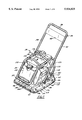
- FIG. 1 is a perspective view of a vibratory plate machine constructed in accordance with a preferred embodiment of the invention
- FIG. 2 is a right side elevation view of the vibratory plate machine of FIG. 1;
- FIG. 3 is a rear elevation view of the vibratory plate machine of FIG. 1;
- FIG. 4 is a top plan view of the vibratory plate machine of FIG. 1;
- FIG. 5 is a bottom plan view of the vibratory plate machine of FIG. 1;
- FIG. 6 is a sectional end elevation view taken through a center portion of an assembly of the vibratory plate machine that includes a console, a baseplate, and an exciter of the machine;
- FIG. 7 is a sectional end elevation view of the assembly of FIG. 6, taken through a front end portion of the assembly;
- FIG. 8 is an exploded perspective view of a portion of the vibratory plate machine that includes the baseplate, the console, and a cage assembly of the machine;
- FIG. 9 is a top plan view of the baseplate
- FIG. 10 is a top plan view of the console/baseplate/exciter assembly
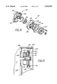
- FIG. 11 is an exploded perspective view of a torque generation assembly of the vibratory plate machine of FIG. 1;
- FIG. 12 is an exploded perspective view of a clutch of the torque generation assembly of FIG. 11.
- FIG. 13 is a partially cut-away, side elevation view of the clutch of FIG. 12 and of the surrounding portions of the torque generation assembly.
- a vibratory plate machine having an improved baseplate, console, clutch, and/or cage assembly.
- the baseplate has a semi-spherical bottom surface and barrel-shaped side surfaces to improve stability and maneuverability.
- the baseplate also has ribs on its upper surface configured to maximize stiffening ability and to channel debris off from the baseplate.
- the console is formed from a single cast metal element to reduce weight and to reduce assembly complexity and to permit shockmounts to be connected to the extreme corner portions of the console.
- the clutch is configured to distribute as much weight as practical to its outer diameter so that it functions as a flywheel to reduce jerking effects on the driven belt to reduce belt wear and increase belt life.
- the cage assembly is configured to maximize protection of sensitive components of the machine such as the water tank and to facilitate machine lifting.
- a vibratory plate machine 20 is illustrated that is suitable for smoothing and/or compacting (henceforth referred to as "compacting" for the sake of simplicity) virtually any granular material such as sand, gravel, aggregate, etc. It is particularly well suited for compacting hot mix asphalt because it incorporates measures to prevent the asphalt from congealing on the machine. However, it is equally well suited for compacting other materials.
- the machine 20 can be conceptually separated into three distinct assemblies, namely: a console/baseplate/exciter assembly 22 (the individual components of which are best seen in FIGS. 6-8); a torque generation assembly 24 (the individual components of which are best seen in FIGS.
- the machine 20 is designed for relatively small scale industrial operations in which an operator walks behind the machine 20 and guides and propels the machine using a handle assembly 28 connected to the console 52 of the console/baseplate/exciter assembly 22.
- the machine 22 is designed for compacting asphalt, it includes a water supply system 30 for preventing asphalt from congealing on the machine 20.
- the handle assembly 28 and water supply system 30 do not per se form part of the present invention apart from their interaction with the remaining inventive features of the machine 20. Hence, they will be described only briefly.
- the handle assembly 28 is formed from a single U-shaped tubular metal member so as to form first and second relatively long side legs 32 and 34 and a center handle 36 connecting the upper end of the side legs 32 and 34 to one another.
- the bottom of each of the side legs 32 and 34 is pivotally attached to the console 52 by a pivot assembly.
- Each pivot assembly includes a sleeve 38 welded to the bottom end of the side leg 32 or 34, one or more bushings (not shown) concentrically received in the sleeve 38, and a pivot pin 40 that extends through the bushing and is threaded into an intermediate sidewall of the console 52.
- the side legs 32 and 34 are bridged near their upper end by a metal plate 42 that serves as a mounting surface for instructions and other indicia and that helps damp vibrations that would otherwise be imposed on the operator's hands.
- the water supply system 30 (FIGS. 1-4) is designed to spray water onto the asphalt surface being compacted directly in front of the machine 20 so that the asphalt does not congeal on a baseplate 50 of the console/baseplate/exciter assembly 22.
- the water supply system 30 includes 1) a storage tank 44 located on the console 52 of the console/baseplate/exciter assembly 22 directly in front of the torque generation assembly 24 and 2) a spray bar 46 mounted on the baseplate 50.
- the spray bar includes a plurality of spaced orifices (not shown) positioned so as to direct water onto the asphalt surface directly in front of the machine 20. Water may be transferred to the spray bar 46 from the tank 44 either directly by gravity or indirectly via an intervening pump that, may for example, be driven by the exciter.
- a pump-fed water supply system forms the subject of a separate application entitled "WATER SUPPLY SYSTEM FOR A VIBRATORY ASPHALT PLATE MACHINE,” filed Jan. 28, 1997 and assigned Ser. No. 08/789,757 and the disclosure of which is hereby incorporated by reference in its entirety for the sake of completeness.
- the console/baseplate/exciter assembly 22 includes a baseplate 50, a console 52 mounted on the baseplate 50, and an exciter 54 mounted on the baseplate 50 beneath the console 52. These components interact with one another and with the remaining components of the machine 20 to improve the stability and maneuverability of the machine 20 while 1) reducing the imposition of vibrations on the console 52 by the exciter 54 and baseplate 50, 2) increasing the durability of the machine 20, 3) reducing the weight of the machine 20, and 4) inhibiting the accumulation of debris between the console 52 and the baseplate 50.
- the baseplate 50 is formed from a single nodular ductile iron plate having 1) a bottom or compacting surface 56 and 2) an upper surface 58 on which are mounted a plurality of reinforcing ribs, an exciter mount, and other mounting bosses. Front, rear, left side, and right side edges or surfaces 60, 62, 64, and 66 of the baseplate 50 all bend or curl upwardly to 1) increase strength, 2) enhance maneuverability and stability, and 3) to reduce ridging or other marring of the surface being compacted. Novel aspects of the baseplate 50 reside in the topography of the bottom surface 56, the bottom plan profile, and the ribs on the upper surface 58. Each of these features will now be detailed.
- the topography of the bottom or compacting surface 56 of the baseplate 50 is designed to enhance stability and maneuverability and to reduce ridging and other marring effects during operation of the machine 20.
- the surface comprises a curved, preferably semi-spherical, convex portion 68 curving downwardly and inwardly from the edges 60, 62, 64, and 66 of the baseplate 50 towards a flat or planar portion 70, with the convex portion 68 surrounding the flat portion 70.
- the flat portion 70 is located underneath the exciter 54 and preferably is centered beneath the exciter 54 both longitudinally and laterally, as shown in FIG. 5.
- the curvature of the semi-spherical portion 68 is very gentle, preferably being above 200" and even more preferably about 550".
- the flat portion 70 is semi-circular in shape, encompassing an arc of about 270° (it would encompass an arc of a full 360° but for the upwardly-curled front edge surface 60 of the baseplate 50).
- the flat region 70 has a diameter of approximately 15".
- the front edge surface 60 is curled upwardly and forwardly from the bottom surface at a radius of approximately 5", and the rear edge surface 62 is curled upwardly and rearwardly from the bottom surface at a radius of approximately 2.5".
- the side edge surfaces 64 and 66 are barrel-shaped when seen in bottom plan view to facilitate maneuvering around corners and other obstructions and to enhance stability. That is, they curl upwardly and outwardly and also curve laterally inwardly so that the bottom surface 56 of the baseplate 50 is substantially wider at the center than at either of its longitudinal ends.
- the upper surface 58 of the baseplate 50 receives an exciter mount frame 72, four shockmount bosses 74, and a plurality of stiffening ribs 76, 78, 80, 82, 84, and 86.
- the exciter mount frame 72 and shockmount bosses 74 are conventional save for the fact that the shockmount bosses 74 are disposed laterally outwardly of conventional shockmount boss mounting positions as discussed in more detail below in connection with the console 52.
- the ribs are dimensioned and configured to provide maximum stiffening with a minimum necessary increase in weight.
- the ribs also are configured to channel debris that accumulates on the upper surface 58 of the baseplate 50 off from the baseplate.
- the ribs include a first rib 76 extending forwardly from the forward edge of the exciter mount frame 72.
- Second and third ribs 78 and 80 are arranged generally co-linear with one another and are located in longitudinal central region of the baseplate 50 so as to extend laterally outwardly from the rear portion of the exciter mount frame 72 towards the side edge surfaces 64 and 66 of the baseplate 50.
- Third, fourth, and fifth ribs 82, 84, and 86 all extend longitudinally rearwardly from the rear wall of the exciter mount frame 72 and are configured individually and with respect to one another to channel debris off from the baseplate 50. Towards these ends, they are each generally triangular in longitudinal profile so that they are higher at their forward ends than at their rear ends.
- the fourth rib 82 extends longitudinally from the center of the rear wall of the exciter mount frame 72.
- the fifth and sixth ribs 84 and 86 extend at an acute angle from respective corners of the exciter mount frame 72 towards respective rear corners of the baseplate 50.
- the rear-wall of the exciter mount frame 72 and the second and third ribs 78 and 80 act as a dam that prevents material that accumulates on the baseplate 50 from moving forwardly of their position.
- the fourth, fifth, and sixth ribs 82, 84, and 86 channel that material off from the baseplate 50 as the baseplate 50 vibrates under action of the exciter 54.
- the exciter 54 is per se conventional and hence will be discussed only briefly.
- the exciter 54 includes a housing 88 which is mounted on the exciter mount frame 72 and in which is disposed an eccentric metal shaft 90.
- the shaft 90 is rotatably supported in bearings 92, 94 that are in turn supported in end caps 96, 98 of the housing 88.
- One end of the shaft 90 extends through its corresponding end cap 96 to receive a driven pulley 100.
- Rotation of the pulley 100 under action of a belt 134 as detailed below causes the shaft 90 to rotate, thereby imparting vibrations to the baseplate 50 in a manner which is per se well known.
- the console 52 is mounted on the baseplate 50 by cylindrical elastomeric shockmounts 102.
- a bolt 106 extends through a hole 104 in each corner of the console 52 and is threaded into the upper axial end of an associated shockmount 102.
- a stud 107 extends inwardly and downwardly from the bottom axial end of each shockmount 102 and is threaded into one of the shockmount bosses 74 on the baseplate 50.
- the console 52 is novel primarily in that it is cast from a single piece of metal, preferably aluminum, rather than being welded from many (typically 25 or more in the past) pieces of steel plate. As seen in FIGS. 6-10, a plurality of reinforcing ribs 108 extend downwardly from the bottom surface of the console 52 for stiffening purposes. A plurality of threaded holes 110 are tapped into flats on the upper surface for receiving mounting screws for the engine 130, cage assembly 26, etc. Lift handles 112 and 114 are fixed to opposed sides of the rear end of the upper surface of the console 52 for facilitating lifting as detailed below. Front and rear stops 116 and 118 are also casted on each side of the console 52 to provide rest points for the side legs 32 and 34 of the handle assembly 28.
- the legs 32 and 34 will normally rest on the rear stops 118 when the machine 20 is not in use and will pivot upwardly some amount when the machine 20 is being operated. However, in some instances in which it is desirable to push the machine 20 under low lying obstructions, the handle assembly 28 can be pivoted forwardly as far as the front stops 116 at which time its maximum height will be lower than the height of the rest of the machine 20 so that the machine 20 can be pushed or pulled under the obstruction.
- the holes 104 for receiving the shockmounts 102 can be located at the extreme corner portions of the console 52 so that the shockmounts 102 are located further towards the corners of the baseplate/exciter/console assembly 22.
- an oil drain trough 120 can be cast into the rear portion of the upper surface of the console 52 so as to have a first end located beneath an oil drain port 122 of the engine 130 (FIG. 3) and a second end terminating at the rear edge surface of the console 52.
- the floor of the trough 120 is recessed with respect to the remainder of the console upper surface, oil that is drained from the engine 130 and into the trough 120 runs directly off from the console 52 rather that spreading in a pool.
- the total labor required to assemble the machine is decreased by about 25% due to the use of the cast one piece console as opposed to the prior art welded console.
- the cast aluminum console 52 is much lighter weight than comparable welded steel consoles.
- the torque generation assembly 24 includes an engine 130, a clutch 132, and a torque transmitting member in the form of a V-belt 134 coupling the clutch 132 to the driven pulley 100 of the exciter 54.
- the engine 130 is a conventional, relatively small (on the order of six horsepower) gasoline powered engine bolted on the upper surface of the console 52 and having a horizontal output shaft 136 as best seen in FIGS. 11 and 13.
- the V-belt 134 extends from the drive pulley 146 of the clutch 132 to the driven pulley 100 of the exciter 54 to transfer torque to the exciter 54.
- a belt guard 138 surrounds the clutch 132 and is connected to a mounting plate 140 disposed in front of the clutch 132.
- the mounting plate 140 is bolted to the engine 130 and to the console 52 as best seen in FIGS. 11 and 13.
- the clutch 132 is of the high inertia, negative engaging type in which engagement occurs automatically upon engine output shaft acceleration with minimal jerking motion.
- the clutch 132 is specially designed to increase belt life by acting as a flywheel that damps jerking motions that would otherwise be imparted to the belt 134 by relative movement between the console 52 (on which the engine 130 and clutch 132 are mounted) and the baseplate 50 (on which the exciter 54 is mounted).
- the clutch 132 is designed to be heavier than standard clutches typically used in applications such as the present invention and to distribute this weight towards the outer diameter of the clutch.
- the clutch 132 includes a shoe assembly 142, a drum 144, and a drive pulley 146.
- the shoe assembly 142 is fixed to the engine output shaft 136 by a key 148.
- Shoe assembly 142 presents three spring-biased shoes 150 which expand outwardly to engage the drum 144 when centrifugal forces imposed by the rotating output shaft 136 are sufficiently high for clutch engagement.
- the drum 144 is rotatably mounted on the shaft 136 by a bearing 152 and is disposed around the shoes 150 so as to be engaged by the shoes 150 upon clutch engagement.
- the drum 144 is fixedly coupled to a drive pulley 146 such that the pulley 146 rotates upon rotation of the drum 144.
- the drum and drive pulley were made from relatively lightweight stamped metal components.
- the drum 144 and an inner section 154 of the drive pulley 146 are formed integrally from a piece of relatively heavy cast metal.
- the drum 144 is also significantly larger in diameter than in a standard drum/pulley arrangement (having a diameter of about 43/4" compared to the standard 33/4" drum.)
- An outer section 156 of the drive pulley 146 is attached to the inner section 154 by studs 158.
- the outer section 156 could be formed either from stamped metal or a separate piece of cast metal.
- the effective width of the pulley 146 can be adjusted to accommodate different belt lengths by adding one or more shims 160 as required between the two pulley sections 154 and 156. Additional spacers 162 are provided at the outer end of the clutch 132 as desired for optimal pulley placement.
- the cage assembly 26 is designed to effectively encase the engine 130 and water tank 44 so as to protect them from damage should the machine 20 be tipped over or otherwise be subjected to external shocks.
- the cage assembly 26 is also designed to facilitate lifting of the machine 20 for site-to-site transport. Towards these ends, the cage assembly 26 is formed from a plurality of interconnected metal tubes which encase the engine 130 and the water tank 44.
- the cage assembly 26 includes first and second side braces 170 and 172 connected to one another by a plurality of cross bars 174, 176, 178, and 180.
- the side braces 170 and 172 are bent into a generally n-shaped profile so as to encase both the engine 130 and the water tank 44 as best seen in FIGS. 1-4 and 8.
- the cross bars include a rear cross bar 174 positioned adjacent the upper end of the engine 130 as best seen in FIG. 3, first and second upper cross bars 176 and 178 extending across and over the engine 130 as best seen in FIGS. 1 and 4, and a front cross bar 180 located adjacent the bottom end of the water tank 44 as best seen in FIG. 1.
- the cage assembly 26 is mounted on the console 52 by rear brackets 182 and 184 attached to the bottom ends of the side braces 170 and 172 and by a front bracket 186 attached to the central portion of the front cross bar 180.
- the upper cross bars 176 and 178 are configured and located to facilitate lifting of the machine 20 while simultaneously providing maximum protection and an aesthetically attractive appearance. Towards these ends, both cross bars 176 and 178 have a shallow inverted V-shape when viewed in side elevation.
- the upper front cross bar 178 is located near the center of mass of the machine 20 so as to enable it to serve as a sole lift point for transporting the machine 20 from site to site.
- the lower front bar 180 and lift handles 112 and 114 can be used in conjunction with one another as an alternative lift arrangement.
- the vibratory plate machine 20 is operated by starting the engine 130 and supplying sufficient throttle to effect clutch engagement, at which point torque is transferred from the clutch 132 to the exciter 54 by way of the V-belt 134. Rotation of the eccentric rotating shaft 90 of the exciter 54 imparts vibrations to the baseplate 50 to compact material. The operator then guides and moves the machine 20 along an intended compaction path using the handle assembly 28.
- the water supply system 30 sprays water onto the asphalt surface directly in front of the machine 20 to prevent asphalt from congealing on the baseplate 50.
- Stability and maneuverability of the machine 20 are enhanced by the semi-spherical, convex portion 68 on the bottom surface 56 of the baseplate 50, and this portion also reduces the possibility that the surface being compacted will be ridged or otherwise marred by operation of the machine 20.
- the barrel-shaped side edge surfaces 64 and 66 of the baseplate 50 also facilitate maneuvering of the machine 20 around obstructions. Any debris that accumulates on the upper surface 58 of the baseplate 50 during machine operation is channeled off from the baseplate 50 by the ribs 78, 80, 82, 84, and 86.
- the relationship between the baseplate 50 and the remainder of the machine 20 limits detrimental effects on the rest of the machine 20 in several ways.
- the vibration damping effectiveness and stability enhancement effectiveness of the shockmounts 102 are maximized, resulting in transmission of minimal vibrations to the console 52 and the operator.
- the cage assembly 28 also facilitates machine lifting and protects the engine 130 and water tank 44 from external shocks.
Landscapes
- Engineering & Computer Science (AREA)
- Architecture (AREA)
- Civil Engineering (AREA)
- Structural Engineering (AREA)
- Road Paving Machines (AREA)
- Apparatuses For Generation Of Mechanical Vibrations (AREA)
Abstract
Description
Claims (14)
Priority Applications (5)
| Application Number | Priority Date | Filing Date | Title |
|---|---|---|---|
| US08/841,936 US5934825A (en) | 1997-01-28 | 1997-04-08 | Vibratory plate machine |
| JP05120098A JP3635389B2 (en) | 1997-01-28 | 1998-01-28 | Diaphragm device |
| ES98101463T ES2210603T3 (en) | 1997-01-28 | 1998-01-28 | PLATE VIBRATING MACHINE. |
| EP98101463A EP0855470B1 (en) | 1997-01-28 | 1998-01-28 | Vibratory plate machine |
| DE69819218T DE69819218T2 (en) | 1997-01-28 | 1998-01-28 | Plate vibrator |
Applications Claiming Priority (3)
| Application Number | Priority Date | Filing Date | Title |
|---|---|---|---|
| US29/065,533 USD393864S (en) | 1997-01-28 | 1997-01-28 | Vibratory asphalt plate |
| US08/789,757 US5890834A (en) | 1997-01-28 | 1997-01-28 | Vibratory plate machine with a water supply system and mehtod of using the same |
| US08/841,936 US5934825A (en) | 1997-01-28 | 1997-04-08 | Vibratory plate machine |
Related Parent Applications (2)
| Application Number | Title | Priority Date | Filing Date |
|---|---|---|---|
| US08/789,757 Continuation-In-Part US5890834A (en) | 1997-01-28 | 1997-01-28 | Vibratory plate machine with a water supply system and mehtod of using the same |
| US29065533 Continuation-In-Part | 1997-01-28 |
Publications (1)
| Publication Number | Publication Date |
|---|---|
| US5934825A true US5934825A (en) | 1999-08-10 |
Family
ID=27120948
Family Applications (1)
| Application Number | Title | Priority Date | Filing Date |
|---|---|---|---|
| US08/841,936 Expired - Lifetime US5934825A (en) | 1997-01-28 | 1997-04-08 | Vibratory plate machine |
Country Status (4)
| Country | Link |
|---|---|
| US (1) | US5934825A (en) |
| EP (1) | EP0855470B1 (en) |
| DE (1) | DE69819218T2 (en) |
| ES (1) | ES2210603T3 (en) |
Cited By (10)
| Publication number | Priority date | Publication date | Assignee | Title |
|---|---|---|---|---|
| US6409426B1 (en) * | 2000-02-22 | 2002-06-25 | Maclellan Kevin | Vibratory tamping tool |
| US6551022B1 (en) * | 1999-11-13 | 2003-04-22 | Benford Limited | Compactor machine having vibration damping means |
| US20080003058A1 (en) * | 2006-07-03 | 2008-01-03 | Dynapac Compaction Equipment Ab. | Vibratory plate |
| US20090035065A1 (en) * | 2007-08-02 | 2009-02-05 | Evolution Power Tools Limited | Compactor |
| US20100296869A1 (en) * | 2008-01-24 | 2010-11-25 | Catanzarite David M | Powered construction ground compactor and method of making |
| US8206061B1 (en) | 2011-05-26 | 2012-06-26 | Caterpillar Inc. | Eccentric vibratory weight shaft for utility compactor |
| CN102561302A (en) * | 2010-10-08 | 2012-07-11 | 宝马格有限公司 | Vibration tamper with tamper base |
| US20140064858A1 (en) * | 2012-09-05 | 2014-03-06 | M-B-W Inc. | Single Direction Vibratory Plate |
| US20140133909A1 (en) * | 2014-01-22 | 2014-05-15 | Caterpillar Paving Products Inc. | Eccentric weight shaft for vibratory compactor |
| CN105332333A (en) * | 2015-11-26 | 2016-02-17 | 宁波市鄞州飞虎机械有限公司 | Flat-plate rammer |
Families Citing this family (3)
| Publication number | Priority date | Publication date | Assignee | Title |
|---|---|---|---|---|
| RU2164973C1 (en) * | 1999-11-18 | 2001-04-10 | Зиганшин Ильнур Тюльпанович | Ground and loose materials compactor |
| RU2231590C2 (en) * | 2002-04-19 | 2004-06-27 | Зиганшин Ильнур Тюльпанович | Tamping vibratory plate |
| RU2231591C1 (en) * | 2002-12-24 | 2004-06-27 | Зиганшин Ильнур Тюльпанович | Tamping vibratory plate |
Citations (17)
| Publication number | Priority date | Publication date | Assignee | Title |
|---|---|---|---|---|
| US3277801A (en) * | 1965-07-29 | 1966-10-11 | Master Cons Inc | Tamper |
| US3292512A (en) * | 1963-10-15 | 1966-12-20 | Schaperclaus Hans Gert | Vibrating earth densifying machine |
| US3314341A (en) * | 1963-10-19 | 1967-04-18 | Delmag Maschinenfabrik | Pole controlled vibrating tamping device |
| US3416418A (en) * | 1965-10-19 | 1968-12-17 | Dyna Quip Inc | Impacting machine |
| US3486568A (en) * | 1968-02-20 | 1969-12-30 | Robert E Westerlund | Hydraulic impact apparatus |
| GB1185946A (en) * | 1967-06-24 | 1970-03-25 | Delmag Verwaltungsgmbh Trading | Stamping Tool for Stamping Ram or the like |
| US3635133A (en) * | 1969-10-29 | 1972-01-18 | Racine Federated Ind Corp | Mounting for compactors |
| US3703127A (en) * | 1970-01-17 | 1972-11-21 | Benno Kaltenegger | Rigid base earth compactor |
| US3782845A (en) * | 1971-08-27 | 1974-01-01 | Koehring Co | Compactor |
| US3817646A (en) * | 1973-04-30 | 1974-06-18 | Wacker Corp | Vibration generator |
| BE898265A (en) * | 1983-11-21 | 1984-03-16 | Callens Henri Evarist | Concrete or asphalt vibrator unit - has hollow foot consisting of light U-shaped bottom plate fixed to heavier U-shaped top plate |
| US4643611A (en) * | 1985-04-08 | 1987-02-17 | Wacker Corporation | Vibratory compactor having improved cast base |
| US4895478A (en) * | 1988-08-22 | 1990-01-23 | M-B-W Inc. | Adjustable handle construction for a compaction apparatus |
| US4966499A (en) * | 1989-12-26 | 1990-10-30 | Fm Industries, Inc. | Vibratory compactor |
| WO1994020693A2 (en) * | 1993-03-09 | 1994-09-15 | M-B-W, Inc. | Drive mechanism for a vibratory compactor |
| US5439314A (en) * | 1994-01-03 | 1995-08-08 | Wadensten; Theodore S. | Reversible self-propelled plate compactor |
| GB2289409A (en) * | 1994-05-20 | 1995-11-22 | Zeiss Stiftung | Porous body for the storage and regulated release of vapourizing substances |
Family Cites Families (3)
| Publication number | Priority date | Publication date | Assignee | Title |
|---|---|---|---|---|
| DE4211284C1 (en) * | 1992-04-03 | 1993-09-30 | Delmag Maschinenfabrik | Electronically controlled ground compactor - uses displacement of steering mass in axial direction of vibrator imbalance weights |
| JPH06193011A (en) * | 1992-12-28 | 1994-07-12 | Howa Mach Ltd | Vibration compacting machine |
| GB2289490A (en) * | 1994-05-20 | 1995-11-22 | Mawsley Machinery Ltd | Vibratory compaction apparatus |
-
1997
- 1997-04-08 US US08/841,936 patent/US5934825A/en not_active Expired - Lifetime
-
1998
- 1998-01-28 EP EP98101463A patent/EP0855470B1/en not_active Expired - Lifetime
- 1998-01-28 ES ES98101463T patent/ES2210603T3/en not_active Expired - Lifetime
- 1998-01-28 DE DE69819218T patent/DE69819218T2/en not_active Expired - Lifetime
Patent Citations (17)
| Publication number | Priority date | Publication date | Assignee | Title |
|---|---|---|---|---|
| US3292512A (en) * | 1963-10-15 | 1966-12-20 | Schaperclaus Hans Gert | Vibrating earth densifying machine |
| US3314341A (en) * | 1963-10-19 | 1967-04-18 | Delmag Maschinenfabrik | Pole controlled vibrating tamping device |
| US3277801A (en) * | 1965-07-29 | 1966-10-11 | Master Cons Inc | Tamper |
| US3416418A (en) * | 1965-10-19 | 1968-12-17 | Dyna Quip Inc | Impacting machine |
| GB1185946A (en) * | 1967-06-24 | 1970-03-25 | Delmag Verwaltungsgmbh Trading | Stamping Tool for Stamping Ram or the like |
| US3486568A (en) * | 1968-02-20 | 1969-12-30 | Robert E Westerlund | Hydraulic impact apparatus |
| US3635133A (en) * | 1969-10-29 | 1972-01-18 | Racine Federated Ind Corp | Mounting for compactors |
| US3703127A (en) * | 1970-01-17 | 1972-11-21 | Benno Kaltenegger | Rigid base earth compactor |
| US3782845A (en) * | 1971-08-27 | 1974-01-01 | Koehring Co | Compactor |
| US3817646A (en) * | 1973-04-30 | 1974-06-18 | Wacker Corp | Vibration generator |
| BE898265A (en) * | 1983-11-21 | 1984-03-16 | Callens Henri Evarist | Concrete or asphalt vibrator unit - has hollow foot consisting of light U-shaped bottom plate fixed to heavier U-shaped top plate |
| US4643611A (en) * | 1985-04-08 | 1987-02-17 | Wacker Corporation | Vibratory compactor having improved cast base |
| US4895478A (en) * | 1988-08-22 | 1990-01-23 | M-B-W Inc. | Adjustable handle construction for a compaction apparatus |
| US4966499A (en) * | 1989-12-26 | 1990-10-30 | Fm Industries, Inc. | Vibratory compactor |
| WO1994020693A2 (en) * | 1993-03-09 | 1994-09-15 | M-B-W, Inc. | Drive mechanism for a vibratory compactor |
| US5439314A (en) * | 1994-01-03 | 1995-08-08 | Wadensten; Theodore S. | Reversible self-propelled plate compactor |
| GB2289409A (en) * | 1994-05-20 | 1995-11-22 | Zeiss Stiftung | Porous body for the storage and regulated release of vapourizing substances |
Non-Patent Citations (12)
| Title |
|---|
| BOMAG brochure: Vibratory Plates 10/36 • BP 15/45, Oct. 1991. |
| BOMAG brochure: Vibratory Plates 10/36 BP 15/45 , Oct. 1991. * |
| M B W Ground Pounder Division brochure: Ground Pounder (date unknown). * |
| M-B-W--Ground Pounder Division brochure: Ground Pounder (date unknown). |
| Patent Abstracts of Japan , vol. 18, No. 544, Oct. 18, 1994 (JP 06 193011; Jul. 12, 1994). * |
| Patent Abstracts of Japan, vol. 18, No. 544, Oct. 18, 1994 (JP 06 193011; Jul. 12, 1994). |
| Stone Construction Equipment, Inc. brochure: Vibratory Plate , 1993. * |
| Stone Construction Equipment, Inc. brochure: Vibratory Plate, 1993. |
| Wacker Corporation brochure: Asphalt Vibratory Plates , Mar., 1996. * |
| Wacker Corporation brochure: Asphalt Vibratory Plates, Mar., 1996. |
| Wacker Corporation brochure: Vibratory Plates , Jan. 1995. * |
| Wacker Corporation brochure: Vibratory Plates, Jan. 1995. |
Cited By (14)
| Publication number | Priority date | Publication date | Assignee | Title |
|---|---|---|---|---|
| US6551022B1 (en) * | 1999-11-13 | 2003-04-22 | Benford Limited | Compactor machine having vibration damping means |
| US6588977B1 (en) * | 1999-11-13 | 2003-07-08 | Benford Limited | Compactor machine having vibration damping means |
| US6409426B1 (en) * | 2000-02-22 | 2002-06-25 | Maclellan Kevin | Vibratory tamping tool |
| US20080003058A1 (en) * | 2006-07-03 | 2008-01-03 | Dynapac Compaction Equipment Ab. | Vibratory plate |
| US7427176B2 (en) | 2006-07-03 | 2008-09-23 | Dynapac Compaction Equipment Ab | Vibratory plate |
| US20090035065A1 (en) * | 2007-08-02 | 2009-02-05 | Evolution Power Tools Limited | Compactor |
| US20100296869A1 (en) * | 2008-01-24 | 2010-11-25 | Catanzarite David M | Powered construction ground compactor and method of making |
| CN102561302A (en) * | 2010-10-08 | 2012-07-11 | 宝马格有限公司 | Vibration tamper with tamper base |
| US8206061B1 (en) | 2011-05-26 | 2012-06-26 | Caterpillar Inc. | Eccentric vibratory weight shaft for utility compactor |
| US20140064858A1 (en) * | 2012-09-05 | 2014-03-06 | M-B-W Inc. | Single Direction Vibratory Plate |
| US9677240B2 (en) * | 2012-09-05 | 2017-06-13 | M-B-W Inc. | Single direction vibratory plate |
| US20140133909A1 (en) * | 2014-01-22 | 2014-05-15 | Caterpillar Paving Products Inc. | Eccentric weight shaft for vibratory compactor |
| US8967910B2 (en) * | 2014-01-22 | 2015-03-03 | Caterpillar Paving Products Inc. | Eccentric weight shaft for vibratory compactor |
| CN105332333A (en) * | 2015-11-26 | 2016-02-17 | 宁波市鄞州飞虎机械有限公司 | Flat-plate rammer |
Also Published As
| Publication number | Publication date |
|---|---|
| EP0855470A2 (en) | 1998-07-29 |
| DE69819218T2 (en) | 2004-04-22 |
| EP0855470B1 (en) | 2003-10-29 |
| DE69819218D1 (en) | 2003-12-04 |
| EP0855470A3 (en) | 1998-09-23 |
| ES2210603T3 (en) | 2004-07-01 |
Similar Documents
| Publication | Publication Date | Title |
|---|---|---|
| US5934825A (en) | Vibratory plate machine | |
| US2737094A (en) | Compactor for asphaltic and other materials | |
| US8038366B2 (en) | Wheeled concrete screeding device | |
| US4386901A (en) | Portable vibrating concrete screed | |
| US5984571A (en) | Vibrating screed | |
| US6953304B2 (en) | Lightweight apparatus for screeding and vibrating uncured concrete surfaces | |
| AU2008346758B2 (en) | Wheeled screeding device | |
| CA1267023A (en) | Walk behind soil compacter having a double vibratory drum and an artificial frame | |
| US2315007A (en) | Rotary excavator | |
| US5890834A (en) | Vibratory plate machine with a water supply system and mehtod of using the same | |
| US5059062A (en) | Concrete path paver with removeable slip-forming screed | |
| CA2411602C (en) | Paver for the paving of ground courses for roads or the like | |
| JP3635389B2 (en) | Diaphragm device | |
| US6447204B1 (en) | Multiple implement screed | |
| US11661714B2 (en) | Boom attachment for a host vehicle | |
| US6336769B1 (en) | Screeding apparatus and components therefor | |
| US6302619B2 (en) | Powered inertia propelled screed apparatus | |
| CA2509069A1 (en) | Vibrating plate | |
| US4878778A (en) | Concrete path paver | |
| US3336848A (en) | Material compactor | |
| RU230254U1 (en) | Universal shovel | |
| JP2571072Y2 (en) | Screed device of asphalt finisher | |
| GB2080868A (en) | Improvements in or relating to apparatus for moulding concrete mix | |
| AU1004702A (en) | Improved screeding apparatus and components therefor | |
| JPS6215299Y2 (en) |
Legal Events
| Date | Code | Title | Description |
|---|---|---|---|
| AS | Assignment |
Owner name: WACKER CORPORATION, WISCONSIN Free format text: ASSIGNMENT OF ASSIGNORS INTEREST;ASSIGNOR:WALDENBERGER, DAVID J.;REEL/FRAME:008524/0766 Effective date: 19970407 |
|
| STCF | Information on status: patent grant |
Free format text: PATENTED CASE |
|
| CC | Certificate of correction | ||
| FEPP | Fee payment procedure |
Free format text: PAYOR NUMBER ASSIGNED (ORIGINAL EVENT CODE: ASPN); ENTITY STATUS OF PATENT OWNER: LARGE ENTITY |
|
| FPAY | Fee payment |
Year of fee payment: 4 |
|
| FPAY | Fee payment |
Year of fee payment: 8 |
|
| AS | Assignment |
Owner name: WACKER NEUSON CORPORATION, WISCONSIN Free format text: CHANGE OF NAME;ASSIGNOR:WACKER CORPORATION;REEL/FRAME:021590/0051 Effective date: 20080331 Owner name: WACKER NEUSON CORPORATION,WISCONSIN Free format text: CHANGE OF NAME;ASSIGNOR:WACKER CORPORATION;REEL/FRAME:021590/0051 Effective date: 20080331 |
|
| FPAY | Fee payment |
Year of fee payment: 12 |
|
| AS | Assignment |
Owner name: WACKER NEUSON PRODUCTION AMERICAS LLC, WISCONSIN Free format text: ASSIGNMENT OF ASSIGNORS INTEREST;ASSIGNOR:WACKER NEUSON CORPORATION;REEL/FRAME:025814/0519 Effective date: 20110203 |