US5924222A - Trench wall cutter - Google Patents
Trench wall cutter Download PDFInfo
- Publication number
- US5924222A US5924222A US08/969,610 US96961097A US5924222A US 5924222 A US5924222 A US 5924222A US 96961097 A US96961097 A US 96961097A US 5924222 A US5924222 A US 5924222A
- Authority
- US
- United States
- Prior art keywords
- cutting
- cutting wheel
- roller
- axis
- rotation
- Prior art date
- Legal status (The legal status is an assumption and is not a legal conclusion. Google has not performed a legal analysis and makes no representation as to the accuracy of the status listed.)
- Expired - Lifetime
Links
- 238000009412 basement excavation Methods 0.000 claims abstract description 25
- 238000005553 drilling Methods 0.000 description 3
- 238000012986 modification Methods 0.000 description 2
- 230000004048 modification Effects 0.000 description 2
- 239000002689 soil Substances 0.000 description 2
- 230000036346 tooth eruption Effects 0.000 description 2
- 230000001419 dependent effect Effects 0.000 description 1
- 238000012423 maintenance Methods 0.000 description 1
- 238000000034 method Methods 0.000 description 1
- 230000002093 peripheral effect Effects 0.000 description 1
- 239000011435 rock Substances 0.000 description 1
- 238000007789 sealing Methods 0.000 description 1
Images

Classifications
-
- E—FIXED CONSTRUCTIONS
- E02—HYDRAULIC ENGINEERING; FOUNDATIONS; SOIL SHIFTING
- E02F—DREDGING; SOIL-SHIFTING
- E02F3/00—Dredgers; Soil-shifting machines
- E02F3/04—Dredgers; Soil-shifting machines mechanically-driven
- E02F3/18—Dredgers; Soil-shifting machines mechanically-driven with digging wheels turning round an axis, e.g. bucket-type wheels
- E02F3/20—Dredgers; Soil-shifting machines mechanically-driven with digging wheels turning round an axis, e.g. bucket-type wheels with tools that only loosen the material, i.e. mill-type wheels
- E02F3/205—Dredgers; Soil-shifting machines mechanically-driven with digging wheels turning round an axis, e.g. bucket-type wheels with tools that only loosen the material, i.e. mill-type wheels with a pair of digging wheels, e.g. slotting machines
-
- E—FIXED CONSTRUCTIONS
- E02—HYDRAULIC ENGINEERING; FOUNDATIONS; SOIL SHIFTING
- E02D—FOUNDATIONS; EXCAVATIONS; EMBANKMENTS; UNDERGROUND OR UNDERWATER STRUCTURES
- E02D17/00—Excavations; Bordering of excavations; Making embankments
- E02D17/13—Foundation slots or slits; Implements for making these slots or slits
Definitions
- the present invention relates to a trench wall cutter with a cutting frame and a gear shield attached thereto.
- the wall cutter includes at least one cutting wheel positioned to turn on its opposite shield sides, and on which roller-shaped excavation tools distributed over the periphery thereof are pivotally mounted. When the cutting wheel is rotating the tools form a cutting wheel cutting surface which runs essentially axially parallel to the axis of rotation of the cutting wheel.
- the trench wall cutting is used to produce trench walls for excavations, seals and foundations.
- U.S. Pat. No. 5,035,071 discloses a trench wall cutter with a cutting frame and gear shield attached thereto. On the opposite shield sides there is at least one cutting wheel each of which can turn, and on which roller-shaped excavation tools are distributed over the periphery thereof and are pivotally mounted thereto. When the cutting wheel is turning the excavation tools form a cutting wheel cutting surface which runs essentially axially parallel to the axis of rotation of the cutting wheel.
- the object of the present invention is to make available a trench wall cutter with roller-shaped excavation tools and with bearings having an especially long service life.
- the trench wall cutter of the present invention is provided with that at least one additional roller pivotally mounted on each cutting wheel, the axis of the roller extending substantially radially with respect to the axis of rotation of the cutting wheel, with one jacket surface of the roller on the face side of the cutting wheel away from the gear shield projecting relative to the face in the direction of the axis of rotation of the cutting wheel.
- the roller can basically be made with a smooth jacket surface which leads to the desired sealing of the side wall of the trench slot.
- the roller is provided with excavation means such as cutting teeth.
- the roller is likewise made as an excavation tool for breaking the soil.
- a slot with accurately defined walls can be formed.
- Especially good drilling progress can be achieved by utilizing roller bits as the excavating tools.
- the excavation tools are made in the shape of truncated cones.
- the respective axis of rotation of the roller-shaped excavation tool can be angled from an axially-parallel location to the axis of rotation of the cutting wheel so that by means of the excavation tools, as the cutting wheel rotates, a cutting wheel cutting surface is furthermore formed which runs axially parallel to the axis of rotation of the cutting wheel.
- Another embodiment of the present invention includes providing a total of four rollers on one cutting wheel, distributed at given angular distances over the cutting wheel. By means of the arrangement of several rollers the load on the individual rollers is reduced. Preferably the rollers are offset at an angle of 60 and 120 degrees to one another at a uniform angular distance or alternately.
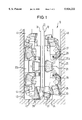
- FIG. 1 shows a partial side view of a trench wall cutter in accordance with the present invention positioned in a trench
- FIG. 2 shows a front view of the trench wall cutter shown in FIG. 1.
- FIG. 1 shows a schematic illustration of the trench wall cutter 10 in accordance with the present invention with a gear shield 11 composed of two shield walls 12 and 13.
- Gear shield 11 is attached in the conventional manner to a cutting frame which is not shown.
- This cutting frame being similar to that disclosed in above mentioned U.S. Pat. No. 5,035,071, the contents of which are hereby incorporated by reference.
- cutting wheels 20a and 20b are rotationally driven by a conventional drive means about an axis of rotation 21 which extends substantially perpendicular to the gear shield 11.
- each cutting wheel 20a, 20b include inner roller bits 22 and outer roller bits 23 in the form of excavation tools.
- the inner roller bits 22 and outer roller bits 23 have roller bodies in the shape of truncated cones with excavation means 28 attached to the truncated surface.
- inner roller bits 22 and outer roller bits 23 are pivotally secured to the periphery of cutting wheels 20a, 20b by means of holders, each holder being diametrically opposed to another holder.
- Axes 24 of the inner roller bits 22 and axes 25 of outer roller bits 23 are substantially axially parallel to the axis of rotation 21 of cutting wheel 20a, 20b, depending on the conical angle of the truncated cone-shaped bodies of inner roller bits 22 or outer roller bits 23, the axis of rotation may be slightly angled.
- the angle setting is chosen such that as cutting wheels 20a, 20b, rotate roller bits 22, 23 form a ground-contacting cutting wheel cutting surface which runs essentially axially parallel to the axis of rotation 21 of cutting wheel 20a, 20b.
- the contact surfaces of the enveloping surfaces of outer roller bits 23 and the enveloping surface of trench 41 are essentially parallel to one another and parallel to the axis of rotation 21 of cutting wheels 20a, 20b.
- rollers 26 are supported on each cutting wheel 20a, 20b adjacent their outer face sides 29.
- the roller axes 27 of the rollers 26 are directed substantially radially to the axis of rotation 21 of cutting wheel 20a, 20b and parallel to shield walls 12, 13 of gear shield 11.
- Rollers 26 are attached via corresponding holders arranged diametrically opposed to one another on the roller wheel hub such that one jacket surface of rollers 26 projects horizontally farther away from gear shield 11 than the peripheral surface of outer roller bits 23. Therefore while outer roller bits 23 first cut a slot at a given width with side wall 43, rollers 26 are provided to form a widened area 44. The widened area 44 is dependent on how far rollers 26 project relative to the outer roller bits 23. In the embodiment shown, rollers 26 themselves are provided with excavation devices such as cutting teeth which are shown only schematically.
- each cutting wheel 20a, 20b there are four rollers 26 for accommodating the lateral forces.
- a total of four rollers 26 are distributed alternatingly at an angular distance of 60 and 120 degrees over the periphery of cutting wheel 20a, 20b.
- This arrangement is the same in the opposing cutting wheels 20a, 20b, opposing cutting wheels 20a, 20b being arranged adjacent to one another on axis of rotation 21 in order to ensure especially good support of the trench wall cutter 10 in the trench 41.
- the described embodiment of the present invention may have a total of four cutting wheels which are located next to one another in pairs.
- rollers 26 By the arrangement of additional rollers 26 with contact surfaces of the enveloping surfaces with the enveloping surface of the trench 41 running essentially parallel to side wall 43 of trench 41, advantageous apportionment of forces on cutting wheels 20a, 20b is achieved.
- the horizontal forces are accommodated by rollers 26, while vertical forces are accommodated mainly by outer roller bits 23.
Landscapes
- Engineering & Computer Science (AREA)
- Mining & Mineral Resources (AREA)
- Structural Engineering (AREA)
- Civil Engineering (AREA)
- General Engineering & Computer Science (AREA)
- Paleontology (AREA)
- Life Sciences & Earth Sciences (AREA)
- General Life Sciences & Earth Sciences (AREA)
- Mechanical Engineering (AREA)
- Excavating Of Shafts Or Tunnels (AREA)
- Road Repair (AREA)
- Knives (AREA)
- Earth Drilling (AREA)
- Processing Of Stones Or Stones Resemblance Materials (AREA)
- Polishing Bodies And Polishing Tools (AREA)
- Dicing (AREA)
- Shovels (AREA)
Abstract
Description
Claims (6)
Applications Claiming Priority (2)
| Application Number | Priority Date | Filing Date | Title |
|---|---|---|---|
| DE19652835A DE19652835C1 (en) | 1996-12-18 | 1996-12-18 | Subterranean cutter dredger |
| DE19652835 | 1996-12-18 |
Publications (1)
| Publication Number | Publication Date |
|---|---|
| US5924222A true US5924222A (en) | 1999-07-20 |
Family
ID=7815242
Family Applications (1)
| Application Number | Title | Priority Date | Filing Date |
|---|---|---|---|
| US08/969,610 Expired - Lifetime US5924222A (en) | 1996-12-18 | 1997-11-13 | Trench wall cutter |
Country Status (12)
| Country | Link |
|---|---|
| US (1) | US5924222A (en) |
| EP (1) | EP0849403B1 (en) |
| JP (1) | JP2971425B2 (en) |
| KR (2) | KR19980064285A (en) |
| CN (1) | CN1070972C (en) |
| AT (1) | ATE196336T1 (en) |
| DE (2) | DE19652835C1 (en) |
| ID (1) | ID19690A (en) |
| MY (1) | MY120217A (en) |
| SG (1) | SG77616A1 (en) |
| TW (1) | TW384334B (en) |
| ZA (1) | ZA9710949B (en) |
Cited By (11)
| Publication number | Priority date | Publication date | Assignee | Title |
|---|---|---|---|---|
| FR2849662A1 (en) * | 2003-01-08 | 2004-07-09 | Cie Du Sol | Milling drum for milling of vertical section, has two sets of rollers mounted around respective axes by making angle less than forty-five degrees and thirty degrees with axis of rotation of drum and cylindrical shell respectively |
| WO2006089866A1 (en) * | 2005-02-22 | 2006-08-31 | Dredging International | Cutter head for dredging soil and method for dredging by means of this cutter head |
| US7178273B2 (en) | 2003-02-27 | 2007-02-20 | Bauer Maschinen Gmbh | Cutting device for cutting trenches in the ground |
| US20070044347A1 (en) * | 2003-02-27 | 2007-03-01 | Maximilian Arzberger | Method for making a trench wall in the ground, trench wall cutter, and trench wall cutting device |
| US20100001574A1 (en) * | 2006-08-31 | 2010-01-07 | Bucyrus Dbt Europe Gmbh | Method and apparatus for the milling cutting of materials |
| EP2369063A1 (en) * | 2010-03-26 | 2011-09-28 | Soletanche Freyssinet | Drilling and mixing tool comprising a drum with separate teeth |
| WO2012156842A3 (en) * | 2011-05-16 | 2013-06-06 | Caterpillar Global Mining Europe Gmbh | Apparatus for the milling cutting of rock, minerals or other materials |
| WO2012156841A3 (en) * | 2011-05-16 | 2013-06-06 | Caterpillar Global Mining Europe Gmbh | Apparatus for the milling cutting of rock, minerals or other materials |
| WO2012156884A3 (en) * | 2011-05-16 | 2013-06-27 | Caterpillar Global Mining Europe Gmbh | Mining installation for extracting seam-type or mass-deposit mineral materials, and mining machine for the same |
| WO2014117814A1 (en) * | 2013-01-29 | 2014-08-07 | Vsl International Ag | Hydromill wheel with single disc cutting rollers |
| CN102216564B (en) * | 2008-10-31 | 2015-08-05 | 阿特拉斯科普柯克雷柳斯有限公司 | Method and apparatus for working on rock |
Families Citing this family (3)
| Publication number | Priority date | Publication date | Assignee | Title |
|---|---|---|---|---|
| CN1252492C (en) | 2003-12-25 | 2006-04-19 | 周仁安 | Measuring method and instrument for earth electromagnetic wave resistivity |
| EP1630298B1 (en) * | 2004-08-23 | 2008-01-16 | BAUER Maschinen GmbH | Method of making a slotted wall by means of a trench cutter |
| EP2636799B1 (en) * | 2012-03-05 | 2014-05-14 | Bauer Spezialtiefbau GmbH | Drilling tool for making a subterraneous curtain wall and method of making such wall |
Citations (6)
| Publication number | Priority date | Publication date | Assignee | Title |
|---|---|---|---|---|
| US3999616A (en) * | 1975-02-03 | 1976-12-28 | The Robbins Company | Method and apparatus for establishing the drilling line of an overhead boring machine |
| US4189186A (en) * | 1978-06-12 | 1980-02-19 | Jarva, Inc. | Tunneling machine |
| US4548442A (en) * | 1983-12-06 | 1985-10-22 | The Robbins Company | Mobile mining machine and method |
| US5035071A (en) * | 1988-10-14 | 1991-07-30 | Bauer Spezialtiefbau Gmbh | Trench wall cutter |
| US5125719A (en) * | 1991-03-29 | 1992-06-30 | Larry Snyder | Tunnel boring machine and method |
| US5308151A (en) * | 1990-05-17 | 1994-05-03 | Z C Mines Pty Ltd. | Cutter wheel assembly for mining machine |
Family Cites Families (3)
| Publication number | Priority date | Publication date | Assignee | Title |
|---|---|---|---|---|
| US4548284A (en) * | 1983-10-28 | 1985-10-22 | Dresser Industries, Inc. | Roller ball retention of reamer cutter assembly |
| JPS61169529A (en) * | 1985-01-23 | 1986-07-31 | Taisei Corp | Excavator for continuous wall |
| DE3933168A1 (en) * | 1988-10-14 | 1990-04-19 | Bauer Spezialtiefbau | Slit wall cutter with counter-rotating cutter wheels - which have rolling tools on their peripheries, overhung in bearings |
-
1996
- 1996-12-18 DE DE19652835A patent/DE19652835C1/en not_active Expired - Fee Related
-
1997
- 1997-11-04 EP EP97119286A patent/EP0849403B1/en not_active Expired - Lifetime
- 1997-11-04 DE DE59702343T patent/DE59702343D1/en not_active Expired - Fee Related
- 1997-11-04 AT AT97119286T patent/ATE196336T1/en not_active IP Right Cessation
- 1997-11-13 US US08/969,610 patent/US5924222A/en not_active Expired - Lifetime
- 1997-11-20 TW TW086117344A patent/TW384334B/en not_active IP Right Cessation
- 1997-12-05 ZA ZA9710949A patent/ZA9710949B/en unknown
- 1997-12-12 SG SG1997004428A patent/SG77616A1/en unknown
- 1997-12-15 MY MYPI97006045A patent/MY120217A/en unknown
- 1997-12-16 JP JP9346339A patent/JP2971425B2/en not_active Expired - Fee Related
- 1997-12-17 KR KR1019970070171A patent/KR19980064285A/en active Granted
- 1997-12-17 KR KR1019970070171A patent/KR100248603B1/en not_active Expired - Lifetime
- 1997-12-18 CN CN97125557A patent/CN1070972C/en not_active Expired - Fee Related
- 1997-12-18 ID IDP973909A patent/ID19690A/en unknown
Patent Citations (6)
| Publication number | Priority date | Publication date | Assignee | Title |
|---|---|---|---|---|
| US3999616A (en) * | 1975-02-03 | 1976-12-28 | The Robbins Company | Method and apparatus for establishing the drilling line of an overhead boring machine |
| US4189186A (en) * | 1978-06-12 | 1980-02-19 | Jarva, Inc. | Tunneling machine |
| US4548442A (en) * | 1983-12-06 | 1985-10-22 | The Robbins Company | Mobile mining machine and method |
| US5035071A (en) * | 1988-10-14 | 1991-07-30 | Bauer Spezialtiefbau Gmbh | Trench wall cutter |
| US5308151A (en) * | 1990-05-17 | 1994-05-03 | Z C Mines Pty Ltd. | Cutter wheel assembly for mining machine |
| US5125719A (en) * | 1991-03-29 | 1992-06-30 | Larry Snyder | Tunnel boring machine and method |
Cited By (36)
| Publication number | Priority date | Publication date | Assignee | Title |
|---|---|---|---|---|
| EP1437445A1 (en) * | 2003-01-08 | 2004-07-14 | Compagnie Du Sol | Milling drum for the making of vertical trenches |
| US20040172857A1 (en) * | 2003-01-08 | 2004-09-09 | Compagnie Du Sol | Drum for an excavator that can be used in particular for the production of vertical trenches in hard of very hard soils |
| US6944977B2 (en) | 2003-01-08 | 2005-09-20 | Compagnie Du Sol | Drum for an excavator that can be used in particular for the production of vertical trenches in hard or very hard soils |
| FR2849662A1 (en) * | 2003-01-08 | 2004-07-09 | Cie Du Sol | Milling drum for milling of vertical section, has two sets of rollers mounted around respective axes by making angle less than forty-five degrees and thirty degrees with axis of rotation of drum and cylindrical shell respectively |
| US7356947B2 (en) * | 2003-02-27 | 2008-04-15 | Bauer Maschinen Gmbh | Method for making a trench wall in the ground, trench wall cutter, and trench wall cutting device |
| CN1928262B (en) * | 2003-02-27 | 2011-06-08 | 包尔机械有限公司 | Trench wall cutting structure |
| US7178273B2 (en) | 2003-02-27 | 2007-02-20 | Bauer Maschinen Gmbh | Cutting device for cutting trenches in the ground |
| US20070044347A1 (en) * | 2003-02-27 | 2007-03-01 | Maximilian Arzberger | Method for making a trench wall in the ground, trench wall cutter, and trench wall cutting device |
| WO2006089866A1 (en) * | 2005-02-22 | 2006-08-31 | Dredging International | Cutter head for dredging soil and method for dredging by means of this cutter head |
| JP2008531868A (en) * | 2005-02-22 | 2008-08-14 | ドレッジング・インターナショナル | Cutter head for dredging soil and method for dredging using this cutter head |
| US20090056173A1 (en) * | 2005-02-22 | 2009-03-05 | Dredging International | Cutter head for dredging soil and method for dredging by means of this cutter head |
| US7647712B2 (en) | 2005-02-22 | 2010-01-19 | Dredging International | Cutter head for dredging soil and method for dredging by means of this cutter head |
| BE1016461A3 (en) * | 2005-02-22 | 2006-11-07 | Dredging Int | CUTTING HEAD FOR DAGGING GROUND AND METHOD FOR DAGGING USING THIS CUTTING HEAD. |
| US20100001574A1 (en) * | 2006-08-31 | 2010-01-07 | Bucyrus Dbt Europe Gmbh | Method and apparatus for the milling cutting of materials |
| US7896445B2 (en) * | 2006-08-31 | 2011-03-01 | Bucyrus Europe Gmbh | Method and apparatus for the milling cutting of materials |
| CN102216564B (en) * | 2008-10-31 | 2015-08-05 | 阿特拉斯科普柯克雷柳斯有限公司 | Method and apparatus for working on rock |
| EP2369063A1 (en) * | 2010-03-26 | 2011-09-28 | Soletanche Freyssinet | Drilling and mixing tool comprising a drum with separate teeth |
| FR2957948A1 (en) * | 2010-03-26 | 2011-09-30 | Soletanche Freyssinet | DRUM FOR MIXING TOOL. |
| WO2012156841A3 (en) * | 2011-05-16 | 2013-06-06 | Caterpillar Global Mining Europe Gmbh | Apparatus for the milling cutting of rock, minerals or other materials |
| US9359893B2 (en) | 2011-05-16 | 2016-06-07 | Caterpillar Global Mining Europe Gmbh | Apparatus for the milling cutting of rock, minerals or other materials |
| GB2504420A (en) * | 2011-05-16 | 2014-01-29 | Caterpillar Global Mining Eur | Apparatus for the milling cutting of rock, minerals or other materials |
| CN103562495A (en) * | 2011-05-16 | 2014-02-05 | 卡特彼勒环球矿业欧洲有限公司 | Apparatus for the milling cutting of rock, minerals or other materials |
| GB2505109A (en) * | 2011-05-16 | 2014-02-19 | Caterpillar Global Mining Eur | Mining installation for extracting seam-type or mass-deposit mineral materials and mining machine for the same |
| GB2505108A (en) * | 2011-05-16 | 2014-02-19 | Caterpillar Global Mining Gmbh | Apparatus for the milling cutting of rock, minerals or other materials |
| AU2012257427B2 (en) * | 2011-05-16 | 2017-06-29 | Caterpillar Global Mining Europe Gmbh | Apparatus for the milling cutting of rock, minerals or other materials |
| WO2012156842A3 (en) * | 2011-05-16 | 2013-06-06 | Caterpillar Global Mining Europe Gmbh | Apparatus for the milling cutting of rock, minerals or other materials |
| US9206685B2 (en) | 2011-05-16 | 2015-12-08 | Caterpillar Global Mining Europe Gmbh | Apparatus for the milling cutting of rock, minerals or other materials |
| WO2012156884A3 (en) * | 2011-05-16 | 2013-06-27 | Caterpillar Global Mining Europe Gmbh | Mining installation for extracting seam-type or mass-deposit mineral materials, and mining machine for the same |
| CN103562495B (en) * | 2011-05-16 | 2016-08-17 | 卡特彼勒环球矿业欧洲有限公司 | Equipment for milling rock, mineral or other materials |
| RU2598004C2 (en) * | 2011-05-16 | 2016-09-20 | Катерпиллар Глобал Майнинг Юроп Гмбх | Device for drilling with rock, minerals or other materials crushing |
| RU2599393C2 (en) * | 2011-05-16 | 2016-10-10 | Катерпиллар Глобал Майнинг Юроп Гмбх | Apparatus for the milling cutting of rock, minerals or other material |
| RU2603147C2 (en) * | 2011-05-16 | 2016-11-20 | Катерпиллар Глобал Майнинг Юроп Гмбх | Mining plant for extraction of mineral materials, lying in the form of formations or arrays and tunneling combine |
| AU2012257511B2 (en) * | 2011-05-16 | 2017-06-15 | Caterpillar Global Mining Europe Gmbh | Apparatus for the milling cutting of rock, minerals or other materials |
| WO2014117814A1 (en) * | 2013-01-29 | 2014-08-07 | Vsl International Ag | Hydromill wheel with single disc cutting rollers |
| EP2951357B1 (en) | 2013-01-29 | 2017-12-13 | VSL International AG | Hydromill wheel with single disc cutting rollers |
| US10669689B2 (en) | 2013-01-29 | 2020-06-02 | Vsl International Ag | Hydromill wheel with single disc cutting rollers |
Also Published As
| Publication number | Publication date |
|---|---|
| JPH10183681A (en) | 1998-07-14 |
| JP2971425B2 (en) | 1999-11-08 |
| SG77616A1 (en) | 2001-01-16 |
| ZA9710949B (en) | 1998-06-15 |
| ATE196336T1 (en) | 2000-09-15 |
| CN1185508A (en) | 1998-06-24 |
| ID19690A (en) | 1998-07-30 |
| EP0849403A1 (en) | 1998-06-24 |
| EP0849403B1 (en) | 2000-09-13 |
| DE59702343D1 (en) | 2000-10-19 |
| KR19980064285A (en) | 1998-10-07 |
| TW384334B (en) | 2000-03-11 |
| MY120217A (en) | 2005-09-30 |
| CN1070972C (en) | 2001-09-12 |
| KR100248603B1 (en) | 2000-03-15 |
| DE19652835C1 (en) | 1998-03-26 |
| HK1010899A1 (en) | 1999-07-02 |
Similar Documents
| Publication | Publication Date | Title |
|---|---|---|
| US5924222A (en) | Trench wall cutter | |
| US6944977B2 (en) | Drum for an excavator that can be used in particular for the production of vertical trenches in hard or very hard soils | |
| CA2661476C (en) | Method and apparatus for the milling cutting of materials | |
| JP6247705B2 (en) | Hydro mill wheel with single disc-type cutting roller | |
| CN1053257C (en) | Shield tunnel boring machine | |
| US4755004A (en) | Rotary rocksaw device | |
| US4189186A (en) | Tunneling machine | |
| TWI830923B (en) | Cutting heads for shield boring machines and obstacle cutting | |
| CN210829279U (en) | Modularized split type shield pipe jacking machine | |
| JP3482023B2 (en) | Replaceable shield excavator | |
| CN215565939U (en) | Spoke rotary type cutting tool | |
| JP2001323780A (en) | Rotary excavating machine of shield propulsion machine | |
| HK1010899B (en) | Trench wall cutter | |
| JP2640849B2 (en) | Tunnel excavator | |
| JPH069110Y2 (en) | Shield excavator cutter | |
| EP2803817B1 (en) | Milling device | |
| CN215406234U (en) | Rolling disc of grooving machine | |
| JP2695801B2 (en) | Shield machine | |
| JP3150655B2 (en) | Underground excavator | |
| CN213743414U (en) | Heavy-load replaceable advanced cutter support for shield cutter | |
| JPS6141839Y2 (en) | ||
| JPH0932482A (en) | Disc cutter device | |
| JPH08319797A (en) | Obstacle cutting device for shield machine | |
| JP2001146890A (en) | Shield excavator | |
| EP1552109A2 (en) | Shield tunneling method and apparatus for excavating a tunnel of non-circular cross section |
Legal Events
| Date | Code | Title | Description |
|---|---|---|---|
| AS | Assignment |
Owner name: BAUER SPEZIALTIEFBAU GMBH, GERMANY Free format text: ASSIGNMENT OF ASSIGNORS INTEREST;ASSIGNOR:STOETZER, ERWIN;REEL/FRAME:008903/0031 Effective date: 19971022 |
|
| STCF | Information on status: patent grant |
Free format text: PATENTED CASE |
|
| AS | Assignment |
Owner name: BAUER MASCHINEN GMBH, GERMANY Free format text: ASSIGNMENT OF ASSIGNORS INTEREST;ASSIGNOR:BAUER SPEZIALTIEFBAU GMBH;REEL/FRAME:013372/0869 Effective date: 20020828 |
|
| FPAY | Fee payment |
Year of fee payment: 4 |
|
| FPAY | Fee payment |
Year of fee payment: 8 |
|
| FPAY | Fee payment |
Year of fee payment: 12 |