US5910001A - Method for adjusting engaged clearance between rotors of screw compressor and apparatus therefor - Google Patents
Method for adjusting engaged clearance between rotors of screw compressor and apparatus therefor Download PDFInfo
- Publication number
- US5910001A US5910001A US08/879,609 US87960997A US5910001A US 5910001 A US5910001 A US 5910001A US 87960997 A US87960997 A US 87960997A US 5910001 A US5910001 A US 5910001A
- Authority
- US
- United States
- Prior art keywords
- rotors
- rotor
- timing
- clearance
- screw compressor
- Prior art date
- Legal status (The legal status is an assumption and is not a legal conclusion. Google has not performed a legal analysis and makes no representation as to the accuracy of the status listed.)
- Expired - Fee Related
Links
Images


Classifications
-
- F—MECHANICAL ENGINEERING; LIGHTING; HEATING; WEAPONS; BLASTING
- F01—MACHINES OR ENGINES IN GENERAL; ENGINE PLANTS IN GENERAL; STEAM ENGINES
- F01C—ROTARY-PISTON OR OSCILLATING-PISTON MACHINES OR ENGINES
- F01C21/00—Component parts, details or accessories not provided for in groups F01C1/00 - F01C20/00
- F01C21/10—Outer members for co-operation with rotary pistons; Casings
- F01C21/102—Adjustment of the interstices between moving and fixed parts of the machine by means other than fluid pressure
-
- Y—GENERAL TAGGING OF NEW TECHNOLOGICAL DEVELOPMENTS; GENERAL TAGGING OF CROSS-SECTIONAL TECHNOLOGIES SPANNING OVER SEVERAL SECTIONS OF THE IPC; TECHNICAL SUBJECTS COVERED BY FORMER USPC CROSS-REFERENCE ART COLLECTIONS [XRACs] AND DIGESTS
- Y10—TECHNICAL SUBJECTS COVERED BY FORMER USPC
- Y10T—TECHNICAL SUBJECTS COVERED BY FORMER US CLASSIFICATION
- Y10T29/00—Metal working
- Y10T29/49—Method of mechanical manufacture
- Y10T29/49229—Prime mover or fluid pump making
- Y10T29/49236—Fluid pump or compressor making
- Y10T29/49242—Screw or gear type, e.g., Moineau type
Definitions
- the present invention relates to a method and an apparatus for adjusting the engaged clearance between rotors of a screw compressor comprising a male rotor and a female rotor inside a casing, both of the rotors being rotated, while maintaining a required very small clearance, by means of timing gears fixed individually to the rotors by a shrink fit, and more particularly relates to a method and an apparatus for adjusting the engaged clearance between rotor of a screw compressor for setting a very small clearance between both rotors to a desired value in a short time.
- a conventional method of adjusting the clearance between rotors of a screw compressor is disclosed in Japanese Patent Application Laid-Open No. 1-155089, where a very small clearance between the rotors is set using a rotating phase difference between male and female rotors as measured by an encoder or the like, under a condition in which one of the rotors is rotated in forward and backward directions, while the other of the rotors has a braking force applied thereto, under a state in which at least one of the timing gears is removed, which is referred to as a timing adjustment or symmetrizing adjustment.
- the setting of a clearance is performed during the assembling process of the screw compressor. Oil hydraulic pressure is applied between one of the timing gears and the rotor on which the one of the timing gears is fixed to loosen the shrink fit between both elements while the movement of the other of the timing gears is being restricted.
- An object of the present invention is to provide a method and an apparatus for adjusting the clearance between rotors of a screw compressor, in which a very small clearance between the rotors can be set to a required value in a short time, and which exhibits a high reliability in the symmetrizing adjustment and a high compressing performance.
- the above object of the present invention can be attained by providing a method of adjusting the engaged clearance between rotors of a screw compressor comprising a male rotor and a female rotor inside a casing, both of the rotors being rotated while maintaining a required very small clearance using timing gears fixed individually to the rotors by means of a shrink fit, the method comprising the steps of loosening the shrink fit between one of the timing gears and the rotor to which the one of the timing gears is fixed while movement of the other of the timing gears is being restricted; and intermittently applying torques to the rotor to which the one of the timing gears is fixed using a servo motor to set the very small clearance between the rotors to a required value.
- the above object of the present invention can be attained by providing a method of adjusting the engaged clearance between rotors of a screw compressor comprising a male rotor and a female rotor inside a casing, both of the rotors being rotated while maintaining a required very small clearance using timing gears fixed individually to the rotors by means of a shrink fit, the method comprising the steps of loosening the shrink fit between one of the timing gears and the rotor on which the one of the timing gears is fixed while movement of the other of the timing gears is being restricted; intermittently applying torques to the rotor to which the one of the timing gears is fixed using a servo motor; applying torques in forward and backward directions to the rotor during the intermittent torque application, each of the forward and backward torques being larger than a static friction force of the driving system of the servo motor and smaller than each torque intermittently applied; calculating a median value of the relative positions of the rotors during the application the forward and backward torques;
- an apparatus for adjusting the engaged clearance between rotors of a screw compressor comprising a male rotor and a female rotor inside a casing, both of the rotors being rotated while maintaining a required very small clearance using timing gears fixed individually to the rotors by means of a shrink fit, which further comprises an intermittent torque applying means for loosening the shrink fit between one of the timing gears and the rotor to which the one of the timing gears is fixed, while movement of the other of the timing gears is being restricted, and intermittently applying torques based on command values to the rotor having the one of the timing gears fixed thereto using a servo motor; a forward and backward torque applying means for applying torques in forward and backward directions to the rotor during the intermittent torque application, each of the forward and backward torques being larger than a static friction force of the driving system of the servo motor and smaller than each torque intermittently applied; a relative position median value calculating means
- the following method was employed in order solve the problem. That is, torques were intermittently applied to the rotor on which the one of the timing gears is mounted using a servo motor, the rotor was allowed to return to its natural shape between applications of the torque, and then a torque value to be applied the next time was determined based on the measured position of the rotor at that time. In that case, it was confirmed that the rotor did not completely return to its natural shape because the static friction force of the servo motor system operated as a restriction force against the rotor returning to its natural shape, and an error remained between the target value of the required very small clearance between the rotors and the actual value of the very small clearance between the rotors after the adjustment.
- a median value of relative positions of both rotors can be calculated during the application of the forward and backward torques.
- the median value corresponds to a median value of residual stresses in the forward and the backward directions caused in the rotor by the static friction force of the servo motor, which can be considered as a position of the rotor under a condition without elastic deformation.
- the very small clearance between the both rotors can be adjusted to the target position as if the rotor having the one of the timing gears mounted thereon is in a state without elastic deformation. Accordingly, it is possible to obtain a screw compressor in which a very small clearance between the rotors can be set to a required value in a short time, and which exhibits a high reliability in the symmetrizing adjustment and a high compressing performance.
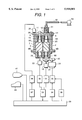
- FIG. 1 is a block diagram showing an embodiment of an apparatus for adjusting the clearance between rotors of a screw compressor in accordance with the present invention.
- FIGS. 2A and 2B are schematic diagrams showing small clearances of rotors and timing gears in the screw compressor shown in FIG. 1.
- FIG. 3 is a diagram showing a state of setting the small clearances of the rotors and the timing gears to a required symmetrizing adjusting position in the screw compressor shown in FIG. 1.
- FIG. 4 is a flow diagram showing the process of adjusting the clearance between rotors of a screw compressor in accordance with the present invention.
- FIG. 5 is a longitudinal section view showing the state of loosing the shrink fitting of one of the timing gears on the rotor as carried out in the process shown in FIG. 4.
- FIG. 6 is a graph showing mutual rotating torque vs. applied hydraulic pressure.
- FIG. 7 is a graph for explaining a state of intermittently applying torques to the rotor through use of a servo motor in the process of FIG. 4.
- FIG. 8 is a graph showing the relationship between the position of the rotor and the target position in the intermittent torque applying operation shown in FIG. 7.
- FIG. 9 is a graph showing the relationship between the position of the rotor and the target position in a case where torques are intermittently applied to the rotor using a servo motor in the process of FIG. 4 in a different way from that shown in FIG. 7.
- FIG. 10 is an enlarged perspective view of the timing gear portion showing the operation of press-fitting an M-timing gear of the screw compressor shown in FIG. 1.
- FIGS. 11A to 11C are diagrams showing a rotating state of the timing gear portion of the screw compressor shown in FIG. 10; wherein FIG. 11A is a partial sectional view, FIG. 11B is a diagram showing an engaging state of the timing gears, and FIG. 11C is a diagram showing an engaging state of the M-timing gear and an outer gear.
- FIGS. 12A and 12B are diagrams showing a rotating state of the rotor portion of the screw compressor shown in FIG. 10; wherein FIG. 12A is a schematic view, and FIG. 12B is a view showing an engaging state of the rotors.
- FIG. 1 is a block diagram showing a screw compressor and an apparatus for adjusting the clearance between rotors of a screw compressor in accordance with the present invention.
- a casing 1 of the screw compressor houses a male rotor 2 and female rotor 3 which are supported in the thrust direction and in the radial direction through ball bearings 4, 5 and roller bearings 6A, 6B, 7A, 7B, respectively.
- the reference characters 8A, 8B, 9A, 9B denote seal rings
- the reference character 10 denotes an M-timing gear of a helical gear fixed by shrink fit to an axle end portion (upper end in FIG.
- the reference character 11 denotes an F-timing gear of the helical gear fixed by shrink fit to an axle end portion (similarly, upper end in FIG. 1) in the delivery side of the female rotor 3
- the reference character 12 denotes a pinion gear fixed by shrink fit to an axle end portion (lower end in FIG. 1) on the suction side of the male rotor 2.
- FIGS. 2A and 2B schematically show a state of the small clearances in the rotors and in the timing gears of the screw compressor shown in FIG. 1.
- An engaging portion (a portion surrounded by a chain line circle aa) of the M-timing gear 10 and the F-timing gear 11 in FIG. 2A is shown in an enlarged view by a circle AA in FIG. 2B
- an engaging portion (a portion surrounded by a chain line circle bb) of the male rotor 2 and the female rotor 3 in FIG. 2A is shown in an enlarged view by a circle BB in FIG. 2B.
- Very small clearances G1, G2 are set on the forward side and the backward side of the rotors 2, 3, respectively.
- the very small clearances G1, G2 are varied by shifting the position of the M-timing gear 10 on the shaft of the male rot
- the timing gear should be fixed at is described in Japanese Patent Application Laid-Open No. 1155089 as follows.
- the M-timing gear 10 is removed from the male rotor 2, the male rotor 2 is rotated forward and backward while the female rotor 3 has a braking force applied thereto through the F-timing gear 11, and the rotating phase difference of each of the rotors 2, 3 is measured using encoders 21, 22 connected to the rotors 2, 3, respectively, during the rotating period (hereinafter, this work is referred to as "measuring work").
- the M-timing gear 10 is fixed to the male rotor 2 through a shrink fit so as to be set to the target position (hereinafter, this work is referred to as "adjusting work").
- FIG. 3 shows a state of setting of the small clearances of the rotors and the timing gears to a required symmetrizing adjusting position in the screw compressor.
- a gear 23 is provided to drive the pinion gear 12 by way of a direct drive servo motor (hereinafter referred to as "DD motor") 24.
- the DD motor 24 is arranged at the bottom of the male rotor 2, where the M-timing gear 10 is not arranged, and applies intermittent torques to the male rotor through the pinion gear 12.
- a servo motor 25 is provided for restricting movement by applying a braking force to the F-timing gear 11 through a gear 26.
- the apparatus for adjusting the engaged clearance between rotors in accordance with the present invention is composed of a plurality of means having the following functions.
- An intermittent torque applying means for loosening the shrinking between one of the timing gears and the rotor on which the one of the timing gears is fixed, while movement of the other of the timing gears is being restricted, and intermittently applying torques based on command values to the rotor on which the one of timing gears is mounted through use of the servo motor.
- a forward and backward torque applying means for applying torques in forward and backward directions to the rotor during the intermittent torque application, each of the torques being larger than a static friction force of the driving system of the servo motor and smaller than each torque intermittently applied.
- a relative position median value calculating means for calculating a median value of relative positions of the rotors during the application of the forward and backward torques.
- An intermittent torque calculating means for calculating the command value of an intermittent torque to be applied next from a difference between the median value and the required value for the very small clearance between both rotors.
- the plurality of means having the above-mentioned functions may be realized by a central control unit (hereinafter referred to as "MPU") 30 and a program for adjusting the engaged clearance between rotors, which program is stored in a memory unit in the MPU (not shown).
- MPU central control unit
- output pulses of the encoders 21, 22 individually connected to the rotors 2, 3 are supplied a counter 33 through interpolators 31, 32 for splitting each of them, and the difference between the rotating phases of the rotors 2, 3 is calculated in the MPU 30.
- the reference character 34 denotes a controller for rotating the DD motor 24 in forward and backward directions through a servo-amplifier 35 during the measuring work
- the reference character 36 denotes a D/A converter for converting a positional command output from the MPU 30 during the adjusting work and for driving the DD motor 24 through the servo-amplifier 35 to drive the male rotor 2 so that the male rotor 2 has a required clearance with respect to the female rotor 3
- the reference character 37 denotes a D/A converter for converting a torque command output from the MPU 30 during measuring work or during adjusting work and for driving the servo motor 25 through a servo-amplifier 38.
- a monitor 41 is provided for displaying a state of processing in the MPU 30, and a printer 42 prints various kinds of data during the measuring work and adjusting work.
- the reference character 51 denotes a press-fitting jig for loosing the shrink fit of the M-timing gear 10 fixed to the male rotor 2 using hydraulic pressure supplied from an oil pressure pump 53 during measuring work or during adjusting work
- the reference character 54 denotes a jig for fixing (restricting the movement of) the M-timing gear 10 to the casing 1 during adjusting work so that the M-timing gear 10 is not rotated with respect to the male rotor 2.
- Step (hereinafter referred to as "S") 1 the various electrical units, such as the encoders 21, 22 and the servo motors 24, 25, are connected to the main body of a compressor, whose M-timing gear 10 is not fixed to the male rotor 2.
- S2 the various electrical units, such as the encoders 21, 22 and the servo motors 24, 25, are connected to the main body of a compressor, whose M-timing gear 10 is not fixed to the male rotor 2.
- the measuring work is performed by positioning control of the servo motor 24 using the controller 34.
- the explanation of the measuring work will be omitted here, since the details are disclosed in Japanese Patent Application Laid-Open No. 1-155089.
- FIG. 5 shows a state in which the press-fitting jig 51 is attached to the male rotor 2.
- the process to achieve the assembled state shown in FIG. 5 is as follows.
- the lower end threaded portion of a piston 51a in the press-fitting jig 51 is fastened to the upper end portion of the male rotor 2 using a threaded connection.
- a cylinder 51b of the press-fitting jig 51 is fixed to the M-timing gear 51 using a threaded connection.
- a pipe 52 is fixed to the upper end portion of the piston 51a using a threaded connection.
- an oil-pressure chamber 51c is partitioned by the M-timing gear 10, the piston 51a and the cylinder 51b.
- the M-timing gear 10 and the F-timing gear 11 are helical gears, they must rotate together along the helical teeth when the M-timing gear is moved to form the state of FIG. 5.
- the M-timing gear 10 is rotated, the male and the female rotors 2, 3 are in contact with each other and rotation of the F-timing gear is prevented since the F-timing gear 11 is fixed to the female rotor 3. Therefore, the M-timing gear 10 tends to rotate around the male rotor 2, but there is produced a torsion between the contact point of the timing gears 10, 11 and the contact point of the both rotors 2, 3.
- the portion (strain) is not released because of the friction force, so that the strain remains even in the state shown in FIG. 5.
- the backlash that is, the clearance between the timing gears 10, 11, is measured.
- the timing gear 11 is slightly driven using the servo motor 25, while movement of the male rotor 2 is restricted using the servo motor 24, and a phase difference between output pulses of the encoders 21, 22, and the backlash to the timing gear 10 is calculated in the MPU 30 using the phase difference.
- the timing gear 10 is fixed to the casing 1 using the fixing jig 54 shown in FIG. 1.
- This adjusting work performs torque control of the servo motor 24 through the D/A converter 36 in S7.
- the F-timing gear 11 is restricted so as to be not rotated within the backlash range of the timing gears by applying a torque toward one direction using the servo motor 25 to keep the timing gears in contact with each other.
- FIG. 6 shows the state of loosening the shrink fitting between the M-timing gear 10 and the male rotor 2, which is obtained from an experiment conducted by the present inventors.
- the abscissa represents oil-hydraulic pressure applied from the oil-pressure pump 53 to the oil-pressure chamber 51c shown in FIG. 5 and the ordinate represents a mutual rotating torque indicating at how large a torque the M-timing gear 10 begins to be rotated against the friction force with the male rotor 2 in response to the hydraulic pressure when the rotating torque is applied to the male rotor 2 using the DD motor 24 shown in FIG. 1.
- intermittent (step-shape) torques are applied to the male rotor 2 by the DD motor 24, as shown in FIG. 7.
- the torque command value V is determined by the MPU 30 calculating a symmetrizing target of clearance between the rotors 2, 3 (target position) in each screw compressor, a median value of relative positions of the rotors during the application of forward and backward torques ((b) and (c) in FIG. 7) which are larger than the static friction force of the driving system of the servo motor and smaller than each of the torques ((a) in FIG. 7) intermittently applied during the intermittent torque application and the characteristic curve shown in FIG. 6.
- FIG. 8 shows the rotational movement (displacement) of the male rotor 2 when the torques shown in FIG. 7 are applied.
- the curve ⁇ 1 represents the difference between detected results of the encoder 21 and the encoder 22, and the curve ⁇ 2 represents an envelope of the displacement of the male rotor 2 in the state in which rotation is returned by releasing of the elastic deformation in the male rotor 2.
- the portion (d) denotes a rotational movement (displacement) of the male rotor 2 corresponding to the intermittently applied torque (a) in FIG. 7, and the portions (e) and (f) are rotational movements of the male rotor 2 corresponding to the forward and the backward torques (b) and (c), respectively, in FIG. 7.
- the portion (i) is a median value of the rotational movements (e) and (f) of the male rotor 2.
- the MPU 30 calculates a median value (i) from outputs of the encoders 21, 22, and confirms the result using the displacement of the male rotor 2 obtained from the curve ⁇ 2 to determine whether the median value is in the symmetrizing target position. If the median value is not in the symmetrizing target position, a torque command value to be applied next is calculated based on the median value (i), that is, from the difference between the position of the male rotor 2 and the target position. Then, the processing is returned to S7 to apply the next intermittent torque.
- the male rotor 2 is driven toward the target position through the intermittently applied torque and the forward and the backward torques, as shown by the curve ⁇ 2.
- the dotted lines in FIG. 8 indicate the tolerance range to the target position. If it is judged in S8 that the position of the male rotor 2 is within the tolerance range and in the symmetrizing target position, the processing advances to S9. By repeating the process of S7 and S8, the clearance of B1+B2 of FIG. 3 falls in the clearance G1+G2. As a result, all the strains produced between the rotors 2, 3, between the timing gears 10, 11 and between the male rotor 2 and the M-timing gear 10 are released.
- the torque command to be applied next is calculated based on the displacement when the median value is not in the symmetrizing target position, and in S8 it is only confirmed using the displacement of the male rotor 2 whether the median value is in the symmetrizing target position.
- an operator can pre-define the time required for the processing to advance to S8.
- the apparatus should be programmed such that the processing advances to S8 every time the process of S7 is executed if the processing returns from S8 to S7.
- the MPU 30 re-determines a final symmetrizing target position from the measured values of S2, S10.
- the press-fitting jig 51 is installed again, and in S13 oil-hydraulic pressure is supplied to the M-timing gear 10 through the press-fitting jig 51 to loosen the shrink fit to the male rotor 2, similar to S4.
- the timing gear backlash is measured and the M-timing gear 10 is fixed to the casing 1 using the fixing jig 54 in the same way as in S5 and S6, though these processes are not shown in the figure.
- the same processes as S7 and S8 are performed to set both rotors 2, 3 to the final symmetrizing target position determined in S11.
- the clearance between the rotors can be adjusted using the MPU 54 automatically, except for the attaching and detaching of the press-fitting jig 51 and the fixing jig 54, and under a state without elastic deformation.
- the forward and the backward torque application is performed by applying the forward torque (b) first and then applying the backward torque (c) in S7 and S14 of FIG. 4.
- this process is designed to obtain the median value (i) between the rotational movements (e) and (f) of the male rotor 2 shown in FIG. 8, it is possible to apply the backward torque (c) first and then apply the forward torque (b).
- the forward torque (b) and the backward torque (c) are applied during a period between the intermittent torque (a) applications, the forward torque (b) and the backward torque (c) can be omitted in a case of a screw compressor having a rotor which can be returned to its natural shape only by the intermittent application of torque.
- FIG. 9 shows the rotational movement (displacement) of the male rotor 2 in a case where only the intermittent torques are applied and the forward and the backward torques are omitted.
- the curve ⁇ 1 represents difference between detected results of the encoder 21 and the encoder 22, and the curve ⁇ 2 is an envelope of the displacement of the male rotor 2 in the state in which rotation is returned by releasing the elastic deformation in the male rotor 2.
- FIG. 10 shows an example of the press-fitting of an M-timing gear.
- the reference character 61 denotes an outer gear which is an alternative to the jig 54 shown in FIG. 1, and the reference character 62 denotes a DD motor for driving the outer gear 61.
- the process of fixing the M-timing gear 10, the piston 51a and the cylinder 51b of the press-fitting jig 51 is the same as the process described with reference to FIG. 5. That is, the lower end screw portion of a piston 51a in the press-fitting jig 51 is fastened to the upper end portion of the male rotor 2 using a threaded condition. A cylinder 51b of the press-fitting jig 51 is fixed to the M-timing gear 51 using a threaded connection. Then, a pipe 52 is fixed to the upper end portion of the piston 51a using a threaded connection. Thereby, an oil-pressure chamber 51c is partitioned by the M-timing gear 10, the piston 51a and the cylinder 51b. On the other hand, in this arrangement, the outer gear 61 is engaged with the M-timing gear 10.
- hydraulic pressure is applied to the M-timing gear 10 is the same manner as used in the conventional press-fitting to loosen the shrink fit by expanding the inner diameter of the timing gear, and at the same time a thrust force (press fitting) is applied in the direction shown by the arrow A in FIG. 11.
- a thrust force pressing fitting
- the M-timing gear 10 is engaged with the helical teeth of the F-timing gear 11.
- the M-timing gear 10 is rotated using the outer gear 61, as shown by the arrow D of FIG. 11A.
- the M-timing gear 10 is rotated, as shown by the arrow E, and is moved and twisted in the inclined direction of the helical teeth of the F-timing gear 11.
- the DD motor 62 and the outer gear 61 are moved in synchronization with the moving speed of the M-timing gear 10, as shown by the arrow F, so that the rotating force is sufficiently transmitted from the outer gear 61 to the M-timing gear 10.
- the M-timing gear 10 is press-fit to the male rotor 2 by being pushed by the outer gear 61, as shown in FIG. 11C, while both timing gears 10, 11 maintain a gap, as shown in FIG. 11B.
- the male rotor 2 is about to rotate as the M-timing gear 10 is being press-fit to the male rotor 2, but the rotors 2, 3 are not in contact with each other as shown in FIG. 12B due to the application of torque in the direction shown by the arrow G opposite to the rotating direction of the M-timing gear 10 using the DD motor 24, as schematically shown in FIG. 12A.
- a position sensor is arranged in the oil pressure cylinder 51b and the movements of the outer gear 61 and the DD motor 62 are controlled using the detected result.
- the rotating angle of the outer gear 61 toward the direction D that is, the controlled amount of movement of the DD motor 62 may be determined from the moving speed of the outer gear 61 toward the direction F based the skew angle of the M-timing gear 10.
- the encoder 21 detecting rotation of the male rotor is not shown in FIG. 12A, the two values of the rotating angles ⁇ 1 and ⁇ 2 detected by the encoders 21, 22 are measured, and the difference between the two values is calculated.
- the calculated result is larger than the backlash between the gear 26 and the F-timing gear 11, it is judged that clash occurs. It is also possible from the positive or negative sign of the calculated result to judge the direction of clash.
- the female rotor 3 has a braking force applied thereto by the servo motor 25 to prevent it from being rotated, and the male rotor 2 is rotated by the DD motor 24.
- the M-timing gear 10 has a braking force applied thereto by the DD motor 62 through the outer gear 61 so that it is not rotated.
- the M-timing gear 10 may be press-fit to the male rotor 2 prior to fitting the F-timing gear 11 to the female rotor 3.
- the symmetrizing adjustment may be performed by restricting the male rotor 2 using the DD motor 24 and applying a torque to the female rotor 3 using the servo motor 25 or the DD motor 62.
Abstract
Description
Claims (12)
Applications Claiming Priority (4)
| Application Number | Priority Date | Filing Date | Title |
|---|---|---|---|
| JP8-173391 | 1996-07-03 | ||
| JP17339196A JP3301918B2 (en) | 1996-07-03 | 1996-07-03 | Rotor position adjustment method for screw compressor |
| JP8-341615 | 1996-12-20 | ||
| JP34161596A JP3639396B2 (en) | 1996-12-20 | 1996-12-20 | Rotor position adjustment method and rotor position adjustment apparatus for screw compressor |
Publications (1)
| Publication Number | Publication Date |
|---|---|
| US5910001A true US5910001A (en) | 1999-06-08 |
Family
ID=26495382
Family Applications (1)
| Application Number | Title | Priority Date | Filing Date |
|---|---|---|---|
| US08/879,609 Expired - Fee Related US5910001A (en) | 1996-07-03 | 1997-06-20 | Method for adjusting engaged clearance between rotors of screw compressor and apparatus therefor |
Country Status (3)
| Country | Link |
|---|---|
| US (1) | US5910001A (en) |
| EP (1) | EP0816683B1 (en) |
| DE (1) | DE69724706T2 (en) |
Cited By (8)
| Publication number | Priority date | Publication date | Assignee | Title |
|---|---|---|---|---|
| US6287088B1 (en) * | 1998-09-17 | 2001-09-11 | Hitachi, Ltd. | Oil free screw compressor |
| US6578437B1 (en) * | 1998-08-07 | 2003-06-17 | Robert Bosch Gmbh | Sensor array for detecting rotation angle and/or torque |
| CN100347450C (en) * | 2003-09-24 | 2007-11-07 | 中国船舶重工集团公司第七一一研究所 | Helical lobe compressor for hydrogen water spray cooled |
| US20150047617A1 (en) * | 2012-03-29 | 2015-02-19 | Eaton Corporation | Variable speed hybrid electric supercharger assembly and method of control of vehicle having same |
| WO2016148775A1 (en) * | 2015-03-16 | 2016-09-22 | Eaton Corporation | Preloaded bearing |
| WO2018093440A1 (en) | 2016-11-16 | 2018-05-24 | Carrier Corporation | Screw compressor with rotor synchronization |
| CN111396310A (en) * | 2020-03-31 | 2020-07-10 | 宁波鲍斯能源装备股份有限公司 | Oil-free screw structure and method for adjusting synchronous rotor clearance thereof |
| US10934951B2 (en) | 2013-03-12 | 2021-03-02 | Eaton Intelligent Power Limited | Adaptive state of charge regulation and control of variable speed hybrid electric supercharger assembly for efficient vehicle operation |
Families Citing this family (2)
| Publication number | Priority date | Publication date | Assignee | Title |
|---|---|---|---|---|
| US11493043B2 (en) | 2018-12-18 | 2022-11-08 | Atlas Copco Airpower, Naamloze Vennootschap | Positive displacement machine with kinematic synchronization coupling and with driven moving parts having their own individual drives |
| EP3899206B1 (en) * | 2018-12-18 | 2023-04-26 | ATLAS COPCO AIRPOWER, naamloze vennootschap | Volumetric machine like a compressor, expander, pump or the like for the displacement of a medium and method thereby used |
Citations (5)
| Publication number | Priority date | Publication date | Assignee | Title |
|---|---|---|---|---|
| JPS5683593A (en) * | 1979-12-11 | 1981-07-08 | Hitachi Ltd | Method of adjusting clearance between two rotors of displacement type compressor |
| JPS5867987A (en) * | 1981-10-19 | 1983-04-22 | Hitachi Ltd | Clearance adjusting method between rotors of screw fluid machine |
| EP0135256A1 (en) * | 1983-06-20 | 1985-03-27 | Eaton Corporation | Supercharger assembly and rotor phasing fixture |
| JPH04232395A (en) * | 1990-12-28 | 1992-08-20 | Honda Motor Co Ltd | Method and device for adjusting rotor clearance |
| JPH0571473A (en) * | 1991-09-06 | 1993-03-23 | Honda Motor Co Ltd | Adjustment method for rotary pump timing gear and device therefor |
Family Cites Families (1)
| Publication number | Priority date | Publication date | Assignee | Title |
|---|---|---|---|---|
| JP2667845B2 (en) | 1987-12-14 | 1997-10-27 | 株式会社日立製作所 | Adjustment method of clearance between rotors of screw fluid machine |
-
1997
- 1997-06-20 US US08/879,609 patent/US5910001A/en not_active Expired - Fee Related
- 1997-06-23 EP EP97110243A patent/EP0816683B1/en not_active Expired - Lifetime
- 1997-06-23 DE DE69724706T patent/DE69724706T2/en not_active Expired - Lifetime
Patent Citations (5)
| Publication number | Priority date | Publication date | Assignee | Title |
|---|---|---|---|---|
| JPS5683593A (en) * | 1979-12-11 | 1981-07-08 | Hitachi Ltd | Method of adjusting clearance between two rotors of displacement type compressor |
| JPS5867987A (en) * | 1981-10-19 | 1983-04-22 | Hitachi Ltd | Clearance adjusting method between rotors of screw fluid machine |
| EP0135256A1 (en) * | 1983-06-20 | 1985-03-27 | Eaton Corporation | Supercharger assembly and rotor phasing fixture |
| JPH04232395A (en) * | 1990-12-28 | 1992-08-20 | Honda Motor Co Ltd | Method and device for adjusting rotor clearance |
| JPH0571473A (en) * | 1991-09-06 | 1993-03-23 | Honda Motor Co Ltd | Adjustment method for rotary pump timing gear and device therefor |
Non-Patent Citations (6)
| Title |
|---|
| Patent Abstracts of Japan vol. 16, No. 585 (M 1347) Dec. 25, 1992 & JP 04 232395 Honda Motor Company Aug. 20, 1992. * |
| Patent Abstracts of Japan vol. 16, No. 585 (M-1347) Dec. 25, 1992 & JP 04 232395 Honda Motor Company Aug. 20, 1992. |
| Patent Abstracts of Japan vol. 5, No. 155 (M 090) Sep. 30, 1981 & JP 56 083593 (Hitachi, Ltd.) Jul. 8, 1981. * |
| Patent Abstracts of Japan vol. 5, No. 155 (M-090) Sep. 30, 1981 & JP 56 083593 (Hitachi, Ltd.) Jul. 8, 1981. |
| Patent Abstracts of Japan, vol. 13 No. 418 (M 871) Sep. 18, 1989 JP 01155089 (Hitachi, Ltd.) Jun. 16, 1989. * |
| Patent Abstracts of Japan, vol. 13 No. 418 (M-871) Sep. 18, 1989 JP 01155089 (Hitachi, Ltd.) Jun. 16, 1989. |
Cited By (14)
| Publication number | Priority date | Publication date | Assignee | Title |
|---|---|---|---|---|
| US6578437B1 (en) * | 1998-08-07 | 2003-06-17 | Robert Bosch Gmbh | Sensor array for detecting rotation angle and/or torque |
| US6287088B1 (en) * | 1998-09-17 | 2001-09-11 | Hitachi, Ltd. | Oil free screw compressor |
| US6471492B2 (en) * | 1998-09-17 | 2002-10-29 | Hitachi, Ltd. | Oil free screw compressor |
| US6638030B2 (en) * | 1998-09-17 | 2003-10-28 | Hitachi, Ltd. | Oil free screw compressor |
| US20040037711A1 (en) * | 1998-09-17 | 2004-02-26 | Hitoshi Nishimura | Oil free screw compressor |
| US6948915B2 (en) | 1998-09-17 | 2005-09-27 | Hitachi, Ltd. | Oil free screw compressor |
| CN100347450C (en) * | 2003-09-24 | 2007-11-07 | 中国船舶重工集团公司第七一一研究所 | Helical lobe compressor for hydrogen water spray cooled |
| US20150047617A1 (en) * | 2012-03-29 | 2015-02-19 | Eaton Corporation | Variable speed hybrid electric supercharger assembly and method of control of vehicle having same |
| US9751411B2 (en) * | 2012-03-29 | 2017-09-05 | Eaton Corporation | Variable speed hybrid electric supercharger assembly and method of control of vehicle having same |
| US10934951B2 (en) | 2013-03-12 | 2021-03-02 | Eaton Intelligent Power Limited | Adaptive state of charge regulation and control of variable speed hybrid electric supercharger assembly for efficient vehicle operation |
| WO2016148775A1 (en) * | 2015-03-16 | 2016-09-22 | Eaton Corporation | Preloaded bearing |
| CN107429609A (en) * | 2015-03-16 | 2017-12-01 | 伊顿公司 | Preload bearing |
| WO2018093440A1 (en) | 2016-11-16 | 2018-05-24 | Carrier Corporation | Screw compressor with rotor synchronization |
| CN111396310A (en) * | 2020-03-31 | 2020-07-10 | 宁波鲍斯能源装备股份有限公司 | Oil-free screw structure and method for adjusting synchronous rotor clearance thereof |
Also Published As
| Publication number | Publication date |
|---|---|
| DE69724706D1 (en) | 2003-10-16 |
| EP0816683B1 (en) | 2003-09-10 |
| EP0816683A1 (en) | 1998-01-07 |
| DE69724706T2 (en) | 2004-07-22 |
Similar Documents
| Publication | Publication Date | Title |
|---|---|---|
| US5910001A (en) | Method for adjusting engaged clearance between rotors of screw compressor and apparatus therefor | |
| JP2005074537A (en) | Connecting rod dividing method and dividing device | |
| US5772494A (en) | Eccentric orbiting type planetary gear device, and its manufacturing method | |
| JP3636104B2 (en) | Rotation transmission device, toothed rotator used therefor, and method of manufacturing rotation transmission device | |
| CN112088073B (en) | Articulated robot and method for estimating gas reduction state of gas spring thereof | |
| US7331206B2 (en) | Method of fabricating component having internal teeth and rolling machine thereof | |
| JP2002147370A (en) | Gear pump or motor | |
| EP0347738B1 (en) | Constant radial clearance gerotor design | |
| JP3639396B2 (en) | Rotor position adjustment method and rotor position adjustment apparatus for screw compressor | |
| US5030072A (en) | Constant radial clearance gerotor design | |
| US4896551A (en) | Starter motor and process of forming pinion shaft used in the starter motor | |
| JPS6259201B2 (en) | ||
| JP3301918B2 (en) | Rotor position adjustment method for screw compressor | |
| CN110549364A (en) | Hydraulic drive high accuracy pendulum favourable turn constructs | |
| JPH0768864B2 (en) | Shield device | |
| JPH1193849A (en) | Test method for screw compressor | |
| JP7169516B2 (en) | Gear pump manufacturing method | |
| CN210998801U (en) | Hydraulic drive high accuracy pendulum favourable turn constructs | |
| JP2528236B2 (en) | Variable preload spindle unit | |
| JP3523247B2 (en) | Inner revolution type differential gear reducer | |
| US20030161748A1 (en) | Internal gear pump that does not contain any filler elements | |
| JP3670785B2 (en) | Method and apparatus for adjusting rotor clearance of screw compressor | |
| RU2098695C1 (en) | Planetary roller helical gearing | |
| JPH09264395A (en) | Pressurizing device of ball screw | |
| JP2580867Y2 (en) | Roller straightening machine |
Legal Events
| Date | Code | Title | Description |
|---|---|---|---|
| AS | Assignment |
Owner name: HITACHI TECHNO ENGINEERING CO., LTD., JAPAN Free format text: ASSIGNMENT OF ASSIGNORS INTEREST;ASSIGNORS:TAKAHASHI, KENICHI;MATSUNO, HIROYUKI;OBATA, HIROYASU;AND OTHERS;REEL/FRAME:008643/0233 Effective date: 19970604 |
|
| FEPP | Fee payment procedure |
Free format text: PAYOR NUMBER ASSIGNED (ORIGINAL EVENT CODE: ASPN); ENTITY STATUS OF PATENT OWNER: LARGE ENTITY |
|
| FPAY | Fee payment |
Year of fee payment: 4 |
|
| FEPP | Fee payment procedure |
Free format text: PAYOR NUMBER ASSIGNED (ORIGINAL EVENT CODE: ASPN); ENTITY STATUS OF PATENT OWNER: LARGE ENTITY Free format text: PAYER NUMBER DE-ASSIGNED (ORIGINAL EVENT CODE: RMPN); ENTITY STATUS OF PATENT OWNER: LARGE ENTITY |
|
| FPAY | Fee payment |
Year of fee payment: 8 |
|
| AS | Assignment |
Owner name: HITACHI PLANT TECHNOLOGIES, LTD., STATELESS Free format text: CHANGE OF NAME;ASSIGNOR:HITACHI TECHNO-ENGINEERING CO., LTD.;REEL/FRAME:019009/0048 Effective date: 20011001 |
|
| AS | Assignment |
Owner name: HITACHI INDUSTRIAL EQUIPMENT SYSTEMS CO., LTD, JAP Free format text: ASSIGNMENT OF ASSIGNORS INTEREST;ASSIGNOR:HITACHI PLANT TECHNOLOGIES, LTD;REEL/FRAME:019984/0810 Effective date: 20070928 |
|
| FEPP | Fee payment procedure |
Free format text: PAYER NUMBER DE-ASSIGNED (ORIGINAL EVENT CODE: RMPN); ENTITY STATUS OF PATENT OWNER: LARGE ENTITY |
|
| FEPP | Fee payment procedure |
Free format text: PAYOR NUMBER ASSIGNED (ORIGINAL EVENT CODE: ASPN); ENTITY STATUS OF PATENT OWNER: LARGE ENTITY |
|
| REMI | Maintenance fee reminder mailed | ||
| LAPS | Lapse for failure to pay maintenance fees | ||
| STCH | Information on status: patent discontinuation |
Free format text: PATENT EXPIRED DUE TO NONPAYMENT OF MAINTENANCE FEES UNDER 37 CFR 1.362 |
|
| FP | Lapsed due to failure to pay maintenance fee |
Effective date: 20110608 |