US5875813A - Automatic back water valve system - Google Patents
Automatic back water valve system Download PDFInfo
- Publication number
- US5875813A US5875813A US08/823,809 US82380997A US5875813A US 5875813 A US5875813 A US 5875813A US 82380997 A US82380997 A US 82380997A US 5875813 A US5875813 A US 5875813A
- Authority
- US
- United States
- Prior art keywords
- valve
- water
- actuator
- passage
- drain line
- Prior art date
- Legal status (The legal status is an assumption and is not a legal conclusion. Google has not performed a legal analysis and makes no representation as to the accuracy of the status listed.)
- Expired - Lifetime
Links
- XLYOFNOQVPJJNP-UHFFFAOYSA-N water Substances O XLYOFNOQVPJJNP-UHFFFAOYSA-N 0.000 title claims abstract description 98
- 239000012530 fluid Substances 0.000 claims abstract description 40
- 239000010865 sewage Substances 0.000 claims abstract description 18
- 239000000463 material Substances 0.000 claims description 8
- 230000000903 blocking effect Effects 0.000 claims description 6
- 230000013011 mating Effects 0.000 claims description 6
- 230000007423 decrease Effects 0.000 claims description 5
- 238000000034 method Methods 0.000 claims description 5
- 230000005484 gravity Effects 0.000 claims 6
- 239000002184 metal Substances 0.000 description 8
- 229910052751 metal Inorganic materials 0.000 description 8
- 239000004033 plastic Substances 0.000 description 8
- 229920003023 plastic Polymers 0.000 description 8
- 230000008878 coupling Effects 0.000 description 7
- 238000010168 coupling process Methods 0.000 description 7
- 238000005859 coupling reaction Methods 0.000 description 7
- 125000006850 spacer group Chemical group 0.000 description 7
- 238000010276 construction Methods 0.000 description 3
- 229910000831 Steel Inorganic materials 0.000 description 2
- 238000006073 displacement reaction Methods 0.000 description 2
- 238000009434 installation Methods 0.000 description 2
- 238000007789 sealing Methods 0.000 description 2
- 229910001220 stainless steel Inorganic materials 0.000 description 2
- 239000010935 stainless steel Substances 0.000 description 2
- 239000010959 steel Substances 0.000 description 2
- 229910001018 Cast iron Inorganic materials 0.000 description 1
- 230000001154 acute effect Effects 0.000 description 1
- 239000011152 fibreglass Substances 0.000 description 1
- 238000002347 injection Methods 0.000 description 1
- 239000007924 injection Substances 0.000 description 1
- 238000003754 machining Methods 0.000 description 1
- 239000013521 mastic Substances 0.000 description 1
- 230000002093 peripheral effect Effects 0.000 description 1
- 230000002441 reversible effect Effects 0.000 description 1
- 239000012056 semi-solid material Substances 0.000 description 1
- 238000003466 welding Methods 0.000 description 1
Images


Classifications
-
- F—MECHANICAL ENGINEERING; LIGHTING; HEATING; WEAPONS; BLASTING
- F16—ENGINEERING ELEMENTS AND UNITS; GENERAL MEASURES FOR PRODUCING AND MAINTAINING EFFECTIVE FUNCTIONING OF MACHINES OR INSTALLATIONS; THERMAL INSULATION IN GENERAL
- F16K—VALVES; TAPS; COCKS; ACTUATING-FLOATS; DEVICES FOR VENTING OR AERATING
- F16K39/00—Devices for relieving the pressure on the sealing faces
- F16K39/06—Devices for relieving the pressure on the sealing faces for taps or cocks
-
- E—FIXED CONSTRUCTIONS
- E03—WATER SUPPLY; SEWERAGE
- E03F—SEWERS; CESSPOOLS
- E03F7/00—Other installations or implements for operating sewer systems, e.g. for preventing or indicating stoppage; Emptying cesspools
- E03F7/02—Shut-off devices
- E03F7/04—Valves for preventing return flow
-
- F—MECHANICAL ENGINEERING; LIGHTING; HEATING; WEAPONS; BLASTING
- F16—ENGINEERING ELEMENTS AND UNITS; GENERAL MEASURES FOR PRODUCING AND MAINTAINING EFFECTIVE FUNCTIONING OF MACHINES OR INSTALLATIONS; THERMAL INSULATION IN GENERAL
- F16K—VALVES; TAPS; COCKS; ACTUATING-FLOATS; DEVICES FOR VENTING OR AERATING
- F16K3/00—Gate valves or sliding valves, i.e. cut-off apparatus with closing members having a sliding movement along the seat for opening and closing
- F16K3/02—Gate valves or sliding valves, i.e. cut-off apparatus with closing members having a sliding movement along the seat for opening and closing with flat sealing faces; Packings therefor
- F16K3/0218—Gate valves or sliding valves, i.e. cut-off apparatus with closing members having a sliding movement along the seat for opening and closing with flat sealing faces; Packings therefor with only one sealing face
-
- F—MECHANICAL ENGINEERING; LIGHTING; HEATING; WEAPONS; BLASTING
- F16—ENGINEERING ELEMENTS AND UNITS; GENERAL MEASURES FOR PRODUCING AND MAINTAINING EFFECTIVE FUNCTIONING OF MACHINES OR INSTALLATIONS; THERMAL INSULATION IN GENERAL
- F16K—VALVES; TAPS; COCKS; ACTUATING-FLOATS; DEVICES FOR VENTING OR AERATING
- F16K3/00—Gate valves or sliding valves, i.e. cut-off apparatus with closing members having a sliding movement along the seat for opening and closing
- F16K3/02—Gate valves or sliding valves, i.e. cut-off apparatus with closing members having a sliding movement along the seat for opening and closing with flat sealing faces; Packings therefor
- F16K3/0281—Guillotine or blade-type valves, e.g. no passage through the valve member
-
- F—MECHANICAL ENGINEERING; LIGHTING; HEATING; WEAPONS; BLASTING
- F16—ENGINEERING ELEMENTS AND UNITS; GENERAL MEASURES FOR PRODUCING AND MAINTAINING EFFECTIVE FUNCTIONING OF MACHINES OR INSTALLATIONS; THERMAL INSULATION IN GENERAL
- F16K—VALVES; TAPS; COCKS; ACTUATING-FLOATS; DEVICES FOR VENTING OR AERATING
- F16K31/00—Actuating devices; Operating means; Releasing devices
- F16K31/12—Actuating devices; Operating means; Releasing devices actuated by fluid
- F16K31/126—Actuating devices; Operating means; Releasing devices actuated by fluid the fluid acting on a diaphragm, bellows, or the like
- F16K31/1266—Actuating devices; Operating means; Releasing devices actuated by fluid the fluid acting on a diaphragm, bellows, or the like one side of the diaphragm being acted upon by the circulating fluid
-
- F—MECHANICAL ENGINEERING; LIGHTING; HEATING; WEAPONS; BLASTING
- F16—ENGINEERING ELEMENTS AND UNITS; GENERAL MEASURES FOR PRODUCING AND MAINTAINING EFFECTIVE FUNCTIONING OF MACHINES OR INSTALLATIONS; THERMAL INSULATION IN GENERAL
- F16K—VALVES; TAPS; COCKS; ACTUATING-FLOATS; DEVICES FOR VENTING OR AERATING
- F16K31/00—Actuating devices; Operating means; Releasing devices
- F16K31/12—Actuating devices; Operating means; Releasing devices actuated by fluid
- F16K31/16—Actuating devices; Operating means; Releasing devices actuated by fluid with a mechanism, other than pulling-or pushing-rod, between fluid motor and closure member
- F16K31/163—Actuating devices; Operating means; Releasing devices actuated by fluid with a mechanism, other than pulling-or pushing-rod, between fluid motor and closure member the fluid acting on a piston
- F16K31/1635—Actuating devices; Operating means; Releasing devices actuated by fluid with a mechanism, other than pulling-or pushing-rod, between fluid motor and closure member the fluid acting on a piston for rotating valves
-
- F—MECHANICAL ENGINEERING; LIGHTING; HEATING; WEAPONS; BLASTING
- F16—ENGINEERING ELEMENTS AND UNITS; GENERAL MEASURES FOR PRODUCING AND MAINTAINING EFFECTIVE FUNCTIONING OF MACHINES OR INSTALLATIONS; THERMAL INSULATION IN GENERAL
- F16K—VALVES; TAPS; COCKS; ACTUATING-FLOATS; DEVICES FOR VENTING OR AERATING
- F16K35/00—Means to prevent accidental or unauthorised actuation
- F16K35/14—Means to prevent accidental or unauthorised actuation interlocking two or more valves
-
- Y—GENERAL TAGGING OF NEW TECHNOLOGICAL DEVELOPMENTS; GENERAL TAGGING OF CROSS-SECTIONAL TECHNOLOGIES SPANNING OVER SEVERAL SECTIONS OF THE IPC; TECHNICAL SUBJECTS COVERED BY FORMER USPC CROSS-REFERENCE ART COLLECTIONS [XRACs] AND DIGESTS
- Y10—TECHNICAL SUBJECTS COVERED BY FORMER USPC
- Y10T—TECHNICAL SUBJECTS COVERED BY FORMER US CLASSIFICATION
- Y10T137/00—Fluid handling
- Y10T137/6851—With casing, support, protector or static constructional installations
- Y10T137/6966—Static constructional installations
- Y10T137/6969—Buildings
- Y10T137/6988—Floor installation
-
- Y—GENERAL TAGGING OF NEW TECHNOLOGICAL DEVELOPMENTS; GENERAL TAGGING OF CROSS-SECTIONAL TECHNOLOGIES SPANNING OVER SEVERAL SECTIONS OF THE IPC; TECHNICAL SUBJECTS COVERED BY FORMER USPC CROSS-REFERENCE ART COLLECTIONS [XRACs] AND DIGESTS
- Y10—TECHNICAL SUBJECTS COVERED BY FORMER USPC
- Y10T—TECHNICAL SUBJECTS COVERED BY FORMER US CLASSIFICATION
- Y10T137/00—Fluid handling
- Y10T137/7722—Line condition change responsive valves
- Y10T137/7781—With separate connected fluid reactor surface
- Y10T137/7793—With opening bias [e.g., pressure regulator]
-
- Y—GENERAL TAGGING OF NEW TECHNOLOGICAL DEVELOPMENTS; GENERAL TAGGING OF CROSS-SECTIONAL TECHNOLOGIES SPANNING OVER SEVERAL SECTIONS OF THE IPC; TECHNICAL SUBJECTS COVERED BY FORMER USPC CROSS-REFERENCE ART COLLECTIONS [XRACs] AND DIGESTS
- Y10—TECHNICAL SUBJECTS COVERED BY FORMER USPC
- Y10T—TECHNICAL SUBJECTS COVERED BY FORMER US CLASSIFICATION
- Y10T137/00—Fluid handling
- Y10T137/7722—Line condition change responsive valves
- Y10T137/7781—With separate connected fluid reactor surface
- Y10T137/7793—With opening bias [e.g., pressure regulator]
- Y10T137/7804—Main flow through isolated reactor chamber
-
- Y—GENERAL TAGGING OF NEW TECHNOLOGICAL DEVELOPMENTS; GENERAL TAGGING OF CROSS-SECTIONAL TECHNOLOGIES SPANNING OVER SEVERAL SECTIONS OF THE IPC; TECHNICAL SUBJECTS COVERED BY FORMER USPC CROSS-REFERENCE ART COLLECTIONS [XRACs] AND DIGESTS
- Y10—TECHNICAL SUBJECTS COVERED BY FORMER USPC
- Y10T—TECHNICAL SUBJECTS COVERED BY FORMER US CLASSIFICATION
- Y10T137/00—Fluid handling
- Y10T137/7722—Line condition change responsive valves
- Y10T137/7781—With separate connected fluid reactor surface
- Y10T137/7793—With opening bias [e.g., pressure regulator]
- Y10T137/7809—Reactor surface separated by apertured partition
Definitions
- a float member is used to sense the water level within the drain line, and the float member operates a controller for controlling a reversible motor which opens and closes a gate valve.
- a back water valve includes a gate valve member which is spring loaded in an open position, and a float senses the elevated water within the drain line and releases or trips the gate valve member for closing in the event the float is elevated by water backing up in the drain line.
- Pat. No. 4,637,425 discloses a flapper-type check valve which has a pivoting valve member.
- valve member is pivoted to a closed position by a spring actuated rod which is released from its cocked position by actuation of a solenoid controlled by a float actuated switch. After the backed up water drains from the sewer line, the check valves are manually reset.
- Other types of fluid actuated gate valves have also been constructed or proposed, for example, as disclosed in U.S. Pat. No. 1,685,932.
- valve for use in a sanitary sewer line extending from a building, it is desirable for the valve to be simple and economical in construction, be dependable and reliable in operation, be easy to assemble and install, avoid any flow restriction in the drain line when valve is open, and be automatic in operation. That is, it is desirable for the valve to close positively when water backs up in the sewer line and then automatically open when the sewer line is again open for use.
- a back water valve which is ideally suited for installation within a sewer line located under the floor of a building and which provides all of the desirable features and advantages mentioned above.
- a back water valve includes a valve body formed by two mating and opposing body sections which are substantially identical and are coupled together to define a straight through drain line passage having an inlet and an outlet.
- the body sections confine therebetween a thin metal gate valve blade member which is supported for vertical reciprocating movement between a lower position which opens the passage and an upper position which closes the passage.
- valve body sections form a circular wall above the passage and which is sealed to the lower end portion of a cylindrical flexible member or bellows defining an expandable chamber.
- the upper end portion of the bellows is closed and receives a circular top cover plate which mounts on the upper end portion of an actuating rod having a lower end portion secured to the top of the blade member.
- a wall surrounds the bellows for protection, and the bottom of the expandable chamber is connected to the drain line by a passage or a port defined in the outlet body section.
- the bellows When the back water valve is installed, the bellows is normally in a collapsed downward position, and the valve blade member is in its lower open position.
- the fluid pressure within the expandable chamber increases by displaced trapped air to expand the bellows and shift the blade member to its upper closed position blocking the drain line passage.
- the fluid pressure within the chamber decreases so that the bellows collapses due to the weight of the top cover plate and automatically returns the blade member to its lower open position.
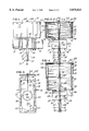
- FIG. 1 is a side elevational view of a back water valve system constructed in accordance with the invention and showing the valve system installed within a drain line;
- FIG. 2 is an axial vertical section of the back water valve system of FIG. 1 and shown in the open position;
- FIG. 4 is a vertical section similar to FIG. 2 and showing the back water valve system in its closed position;
- FIG. 5 is a perspective view of a back water valve system constructed in accordance with a second embodiment of the invention and shown installed under a basement floor;
- FIG. 6 is a fragmentary section taken generally on the line 6--6 of FIG. 5;
- FIG. 7 is a plan view taken on the line 7--7 of FIG. 6;
- FIG. 8 is a section similar to FIG. 2 and showing the second embodiment of the valve system in its open position.
- FIG. 9 is a section similar to FIG. 8 and showing the valve system in its closed position.
- FIG. 1 illustrates a back water valve system 10 constructed in accordance with the invention and installed within a conventional sewer line 12 which may be plastic or cast iron.
- the valve 10 includes a valve body 15 which is formed by two mating and opposing body sections 16 and 18. Each of the body sections is shown as constructed of cast metal but may also be injection molded of a rigid plastics material.
- the body section 16 includes a generally flat rectangular wall 22 from which projects a cylindrical outlet coupling portion 23 and a semi-circular top wall 26.
- the valve body section 18 includes a generally flat rectangular wall 28, a cylindrical inlet coupling portion 29 and a semi-circular top wall 32.
- a frame-like stainless steel spacer plate 34 is confined or sandwiched between the walls 22 and 28 with suitable gaskets or sealing mastic, and the walls 22 and 28 are secured together by peripherally spaced bolts 37.
- Each of the walls 22 and 28 defines a shallow rectangular cavity 41 (FIG. 2), and the spacer plate 34 is provided with inwardly projecting tabs 43 (FIG. 3) which cooperate with the walls 22 and 28 to form a track or channel for a sliding stainless steel gate valve blade member 45.
- the blade member 45 is generally rectangular with a V-shaped lower edge surface 47 and a circular hole or opening 48 within its upper portion.
- the bellows 80 has an integrally molded top wall 92 which cooperates with the side wall 82 and the wall sections 26 and 32 to define an expandable fluid chamber 95 which surrounds the upper portions of the connected flat body walls 22 and 28.
- the chamber 95 is connected to the drain line passage 65 by a port or opening 97 formed within a boss 98 at the top of the outlet coupling portion 23.
- the bellows 80 In this closed position, the bellows 80 is fully expanded and the air pressure within the upper portion of the chamber 95 is sufficient, for example, over 0.25 psi, to hold the valve 10 in its closed position where the blade member 45 engages the upper end portion of the spacer plate 34.
- the valve system 10 When the valve system 10 is closed, any further increase in the fluid pressure within the backed up sewage water is blocked at the outlet 69 of the passage 65. Since the sewage drain line 12 is usually located a couple feet below a building floor surface, the back water valve system 10 is effective to prevent the sewage water from backing up within the sewer line 12 to a level above the floor surface.
- a back water valve system or unit 120 is submerged within a surrounding cylindrical fiberglass casing 122 recessed within a basement floor 124 of a building.
- the valve unit 120 is connected within a drain line 126 which extends in the ground G under a basement floor 124 and the footer for a basement wall 128.
- the drain line 126 extends from the valve unit 120 to an elbow 131 and a drain outlet 132 within the basement floor 124.
- the back water valve unit 120 is constructed generally the same as the valve unit 10 described above in connection with FIGS. 1-4, and accordingly, the same reference numbers are used for corresponding parts or components but with the addition of prime marks.
- a valve body 15' (FIGS. 8 & 9) includes mating body sections 16' and 18' which are illustrated in cast metal but may also be molded of a rigid plastics material. The valve body sections 16' and 18' are clamped together by the bolts 37' and confined therebetween a valve member or blade 45' having a port 48'.
- a blade actuator rod 54' projects upwardly from the blade 45' between the walls 22' and 28', and a diaphragm-like bellows 80' has a center portion secured to the actuating rod 54' by a top plate 102' and a nut 104'.
- a resilient sealing ring 136 is confined within a groove within the walls and surrounds the rod 54'.
- drain line extension 152 and the line 160 form a fluid passage for back-up water within the drain line 126 to flow into and out of the chamber 158 through the trap 154 and also a passage for displaced air within the chamber 158 to flow into and out of the chamber 95'.
- the back water valve system 120 including the back water extension 152 and the fixed air displacement chamber 158 are ideally suited for use within a drain line 126 which is close to the basement floor 124 of a building, for example, from four to twelve inches below the floor 124.
- the operation of the back water valve system 120 is generally the same as the operation of the back water valve system 10 described above. That is, when the drain line 126 is essentially empty and filled with air, the drain water has a level 164 within the trap 154 so that air within the chamber 158 is effectively trapped by the water at the level 164. As water begins to back up within the drain line 126, the water raises in the chamber 158 towards a level 166 thereby compressing the trapped air within the chamber.
- the compressed air within the chamber 158 flows through the passage within the line 160 and into the chamber 95'.
- air pressure within the chamber 95' is sufficient to have moved the bellows 80' and the valve member 45' from the open position (FIG. 8) to the closed position (FIG. 9) as a result of the increased pressure within the chamber 95'.
- a back water valve system constructed in accordance with the present invention, provides desirable features and advantages.
- the back water valve system 10 or 120 is simple, compact and economical in construction and also dependable in operation.
- the valve system operates automatically without the need for electrical power and provides no restriction to the flow of drain water when the valve is in its open position.
- the valve body sections 16 and 18 or 16' and 18' are substantially identical except for the opening or port 97 in the section 16 or the passage for the air line 160. Thus when the valve body sections are cast in metal, the same mold may be used.
- the telescopic cylindrical shrouds 86 and 110 or the inverted stationary enclosure 142 is provided to protect the flexible bellows 80 or 80', but are not required for the performance or operation of the back water valve.
- the arrangement of the gate valve blade member 45 or 45' with a lower open position and an upper closed position, and its continuous contact with the O-rings 49, are also desirable. This assures that the path for the blade member is always open and that the O-rings 49 form dependable fluid-tight seals when the valve is closed.
- the portion of the blade member defining the lower half of the opening 48 or 48' may also be provided with a sharp edge in order to shear through any semi-solid material which might be within the opening and interfere with the closing of the blade member.
Landscapes
- Engineering & Computer Science (AREA)
- General Engineering & Computer Science (AREA)
- Mechanical Engineering (AREA)
- Health & Medical Sciences (AREA)
- Life Sciences & Earth Sciences (AREA)
- Hydrology & Water Resources (AREA)
- Public Health (AREA)
- Water Supply & Treatment (AREA)
- Fluid-Driven Valves (AREA)
- Multiple-Way Valves (AREA)
Priority Applications (6)
| Application Number | Priority Date | Filing Date | Title |
|---|---|---|---|
| US08/823,809 US5875813A (en) | 1995-01-24 | 1997-03-24 | Automatic back water valve system |
| NZ50036098A NZ500360A (en) | 1997-03-24 | 1998-03-24 | Automatic back water valve system with back-up of water causing actuation of bellows attached to valve lifting device |
| CA 2284741 CA2284741C (fr) | 1997-03-24 | 1998-03-24 | Clapet automatique anti-retour d'eau |
| AU65861/98A AU732115B2 (en) | 1997-03-24 | 1998-03-24 | Automatic back water valve system |
| PCT/US1998/005936 WO1998043008A1 (fr) | 1997-03-24 | 1998-03-24 | Clapet automatique anti-retour d'eau |
| US09/260,429 US6131595A (en) | 1995-01-24 | 1999-03-01 | Automatic back water valve system |
Applications Claiming Priority (3)
| Application Number | Priority Date | Filing Date | Title |
|---|---|---|---|
| US08/377,196 US5538032A (en) | 1995-01-24 | 1995-01-24 | Automatic back water valve system |
| US68103796A | 1996-07-22 | 1996-07-22 | |
| US08/823,809 US5875813A (en) | 1995-01-24 | 1997-03-24 | Automatic back water valve system |
Related Parent Applications (1)
| Application Number | Title | Priority Date | Filing Date |
|---|---|---|---|
| US68103796A Continuation-In-Part | 1995-01-24 | 1996-07-22 |
Related Child Applications (1)
| Application Number | Title | Priority Date | Filing Date |
|---|---|---|---|
| US09/260,429 Continuation-In-Part US6131595A (en) | 1995-01-24 | 1999-03-01 | Automatic back water valve system |
Publications (1)
| Publication Number | Publication Date |
|---|---|
| US5875813A true US5875813A (en) | 1999-03-02 |
Family
ID=25239791
Family Applications (1)
| Application Number | Title | Priority Date | Filing Date |
|---|---|---|---|
| US08/823,809 Expired - Lifetime US5875813A (en) | 1995-01-24 | 1997-03-24 | Automatic back water valve system |
Country Status (5)
| Country | Link |
|---|---|
| US (1) | US5875813A (fr) |
| AU (1) | AU732115B2 (fr) |
| CA (1) | CA2284741C (fr) |
| NZ (1) | NZ500360A (fr) |
| WO (1) | WO1998043008A1 (fr) |
Cited By (5)
| Publication number | Priority date | Publication date | Assignee | Title |
|---|---|---|---|---|
| US6131595A (en) * | 1995-01-24 | 2000-10-17 | Cook; William H. | Automatic back water valve system |
| US6311949B1 (en) * | 1997-12-11 | 2001-11-06 | Akio Iida | Apparatus for operating water gate |
| US11560697B2 (en) | 2020-04-17 | 2023-01-24 | Backwater Solutions Canada Inc. | Backwater flow detection device |
| US11933417B2 (en) | 2019-09-27 | 2024-03-19 | Rain Bird Corporation | Irrigation sprinkler service valve |
| US12030072B2 (en) | 2020-11-16 | 2024-07-09 | Rain Bird Corporation | Pressure regulation device and method for irrigation sprinklers |
Families Citing this family (3)
| Publication number | Priority date | Publication date | Assignee | Title |
|---|---|---|---|---|
| FR2844329B1 (fr) * | 2002-09-06 | 2004-11-26 | Claude Bresso | Dispositif de fermeture automatique d'une canalisation d'ecoulement d'un liquide dans un canal |
| FR2901006B1 (fr) * | 2006-05-09 | 2008-07-18 | Peugeot Citroen Automobiles Sa | Valve et systeme de limitation de debit d'air entrant de pompe a vide d'un vehicule |
| FR2977007B1 (fr) * | 2011-06-27 | 2015-06-26 | Cattin Filtration | Registre a glissiere pour systeme d'extraction de fluide et installation comportant un tel registre a glissiere |
Citations (12)
| Publication number | Priority date | Publication date | Assignee | Title |
|---|---|---|---|---|
| US1685932A (en) * | 1926-01-15 | 1928-10-02 | Walter B Andersson | Hydraulic gate and check valve |
| US1991081A (en) * | 1932-10-21 | 1935-02-12 | Charpier Walter | Automatic back water valve |
| US2431399A (en) * | 1945-05-28 | 1947-11-25 | George A Hull | Back water trap for drains |
| US2904064A (en) * | 1957-05-08 | 1959-09-15 | Mace W Davis | Backwater valve |
| US3115890A (en) * | 1961-09-18 | 1963-12-31 | Greenbaum Maurice | Flood control valve |
| US3213764A (en) * | 1963-11-27 | 1965-10-26 | Bendix Corp | Damped bellows construction |
| US3486731A (en) * | 1968-05-17 | 1969-12-30 | Bendix Corp | Control apparatus with pivotal lever for transmitting motion |
| US4187873A (en) * | 1972-02-09 | 1980-02-12 | Raphael Mehoudar | Pressure regulators |
| US4257447A (en) * | 1979-01-29 | 1981-03-24 | The Clarkson Company | Gate valve |
| US4432388A (en) * | 1982-01-07 | 1984-02-21 | Jerome Rest | Device for preventing sewage backup in drain lines |
| US4637425A (en) * | 1986-06-02 | 1987-01-20 | Petersen Robert E | Sewer check valve with cutting seat |
| US5538032A (en) * | 1995-01-24 | 1996-07-23 | Cook; William H. | Automatic back water valve system |
-
1997
- 1997-03-24 US US08/823,809 patent/US5875813A/en not_active Expired - Lifetime
-
1998
- 1998-03-24 AU AU65861/98A patent/AU732115B2/en not_active Ceased
- 1998-03-24 CA CA 2284741 patent/CA2284741C/fr not_active Expired - Fee Related
- 1998-03-24 NZ NZ50036098A patent/NZ500360A/xx unknown
- 1998-03-24 WO PCT/US1998/005936 patent/WO1998043008A1/fr not_active Ceased
Patent Citations (12)
| Publication number | Priority date | Publication date | Assignee | Title |
|---|---|---|---|---|
| US1685932A (en) * | 1926-01-15 | 1928-10-02 | Walter B Andersson | Hydraulic gate and check valve |
| US1991081A (en) * | 1932-10-21 | 1935-02-12 | Charpier Walter | Automatic back water valve |
| US2431399A (en) * | 1945-05-28 | 1947-11-25 | George A Hull | Back water trap for drains |
| US2904064A (en) * | 1957-05-08 | 1959-09-15 | Mace W Davis | Backwater valve |
| US3115890A (en) * | 1961-09-18 | 1963-12-31 | Greenbaum Maurice | Flood control valve |
| US3213764A (en) * | 1963-11-27 | 1965-10-26 | Bendix Corp | Damped bellows construction |
| US3486731A (en) * | 1968-05-17 | 1969-12-30 | Bendix Corp | Control apparatus with pivotal lever for transmitting motion |
| US4187873A (en) * | 1972-02-09 | 1980-02-12 | Raphael Mehoudar | Pressure regulators |
| US4257447A (en) * | 1979-01-29 | 1981-03-24 | The Clarkson Company | Gate valve |
| US4432388A (en) * | 1982-01-07 | 1984-02-21 | Jerome Rest | Device for preventing sewage backup in drain lines |
| US4637425A (en) * | 1986-06-02 | 1987-01-20 | Petersen Robert E | Sewer check valve with cutting seat |
| US5538032A (en) * | 1995-01-24 | 1996-07-23 | Cook; William H. | Automatic back water valve system |
Cited By (5)
| Publication number | Priority date | Publication date | Assignee | Title |
|---|---|---|---|---|
| US6131595A (en) * | 1995-01-24 | 2000-10-17 | Cook; William H. | Automatic back water valve system |
| US6311949B1 (en) * | 1997-12-11 | 2001-11-06 | Akio Iida | Apparatus for operating water gate |
| US11933417B2 (en) | 2019-09-27 | 2024-03-19 | Rain Bird Corporation | Irrigation sprinkler service valve |
| US11560697B2 (en) | 2020-04-17 | 2023-01-24 | Backwater Solutions Canada Inc. | Backwater flow detection device |
| US12030072B2 (en) | 2020-11-16 | 2024-07-09 | Rain Bird Corporation | Pressure regulation device and method for irrigation sprinklers |
Also Published As
| Publication number | Publication date |
|---|---|
| CA2284741C (fr) | 2002-12-24 |
| NZ500360A (en) | 2001-03-30 |
| AU732115B2 (en) | 2001-04-12 |
| WO1998043008A1 (fr) | 1998-10-01 |
| AU6586198A (en) | 1998-10-20 |
| CA2284741A1 (fr) | 1998-10-01 |
Similar Documents
| Publication | Publication Date | Title |
|---|---|---|
| US6719004B2 (en) | Check valve floor drain | |
| KR101320241B1 (ko) | 진공 밸브의 제어 장치 | |
| US5351709A (en) | Control valves | |
| US6318397B1 (en) | Side port floor drain | |
| US5875813A (en) | Automatic back water valve system | |
| US3865512A (en) | Control apparatus for a water supply system | |
| US4188978A (en) | Valve mechanism | |
| US5538032A (en) | Automatic back water valve system | |
| MXPA03011845A (es) | Drenaje de piso con valvula de retencion. | |
| US6131595A (en) | Automatic back water valve system | |
| US4060341A (en) | Automatic auxiliary jet sump pump | |
| CA2437379C (fr) | Robinet a manchon de type deversoir flexible | |
| AU2017285708B2 (en) | A freeze prevention valve | |
| MXPA99008711A (en) | Automatic back water valve system | |
| JPH07269739A (ja) | 弁組立体 | |
| WO2008115164A2 (fr) | Clapet à pincement | |
| US810390A (en) | Back-pressure trap for sewer-pipes. | |
| CA2334742C (fr) | Valve de purge automatique | |
| JPS6227202B2 (fr) | ||
| EP0031988A1 (fr) | Mécanisme pour vanne | |
| US5343572A (en) | Pressured toilet tank flush valve | |
| JP4022945B2 (ja) | 減圧式逆流防止型ドレンバルブ | |
| ATE37058T1 (de) | Rohrtrenner, insbesondere fuer trinkwasserleitungen. | |
| JP2001311635A (ja) | フロースイッチ | |
| SU1091131A1 (ru) | Устройство дл автоматического регулировани уровн воды |
Legal Events
| Date | Code | Title | Description |
|---|---|---|---|
| STCF | Information on status: patent grant |
Free format text: PATENTED CASE |
|
| FPAY | Fee payment |
Year of fee payment: 4 |
|
| FPAY | Fee payment |
Year of fee payment: 8 |
|
| FPAY | Fee payment |
Year of fee payment: 12 |