US5862987A - Non-metallic spray nozzle manifold and support therefor - Google Patents
Non-metallic spray nozzle manifold and support therefor Download PDFInfo
- Publication number
- US5862987A US5862987A US08/844,301 US84430197A US5862987A US 5862987 A US5862987 A US 5862987A US 84430197 A US84430197 A US 84430197A US 5862987 A US5862987 A US 5862987A
- Authority
- US
- United States
- Prior art keywords
- header
- mounting surface
- integrally formed
- cylindrical bore
- nozzle
- Prior art date
- Legal status (The legal status is an assumption and is not a legal conclusion. Google has not performed a legal analysis and makes no representation as to the accuracy of the status listed.)
- Expired - Fee Related
Links
Images

Classifications
-
- B—PERFORMING OPERATIONS; TRANSPORTING
- B05—SPRAYING OR ATOMISING IN GENERAL; APPLYING FLUENT MATERIALS TO SURFACES, IN GENERAL
- B05B—SPRAYING APPARATUS; ATOMISING APPARATUS; NOZZLES
- B05B1/00—Nozzles, spray heads or other outlets, with or without auxiliary devices such as valves, heating means
- B05B1/14—Nozzles, spray heads or other outlets, with or without auxiliary devices such as valves, heating means with multiple outlet openings; with strainers in or outside the outlet opening
- B05B1/20—Arrangements of several outlets along elongated bodies, e.g. perforated pipes or troughs, e.g. spray booms; Outlet elements therefor
- B05B1/202—Arrangements of several outlets along elongated bodies, e.g. perforated pipes or troughs, e.g. spray booms; Outlet elements therefor comprising inserted outlet elements
-
- A—HUMAN NECESSITIES
- A01—AGRICULTURE; FORESTRY; ANIMAL HUSBANDRY; HUNTING; TRAPPING; FISHING
- A01M—CATCHING, TRAPPING OR SCARING OF ANIMALS; APPARATUS FOR THE DESTRUCTION OF NOXIOUS ANIMALS OR NOXIOUS PLANTS
- A01M7/00—Special adaptations or arrangements of liquid-spraying apparatus for purposes covered by this subclass
- A01M7/005—Special arrangements or adaptations of the spraying or distributing parts, e.g. adaptations or mounting of the spray booms, mounting of the nozzles, protection shields
- A01M7/006—Mounting of the nozzles
Definitions
- the present invention relates generally to liquid manifolds and headers, and particularly, to manifolds and headers which support and communicate liquid to a plurality of spray nozzles supported thereon.
- a plurality of spray nozzles In many industrial, agricultural, and commercial fluid spraying applications, it is necessary for a plurality of spray nozzles to be mounted in a longitudinal array. It is common to support such a plurality of spray nozzles along the length of an elongated manifold pipe, commonly known as a header, and to communicate liquid from a supply source through the manifold to the plurality of nozzles.
- manifolds typically are formed from stainless steel pipe, and by virtue of their long length, can be heavy and difficult to handle, assembly, and support. While it is often desirable that the manifold have a relatively large diameter, both to enable large volume liquid passage and to facilitate nozzle attachment and internal threading and axial coupling of components thereon, increasing the diameter of the header further increases the weight and difficulty in handling. Thus, it is often difficult to implement large diameter manifolds in known fluid spraying systems.
- Another object is to provide a header as characterized above with a relatively simple and reliable mounting arrangement.
- a further object is to provide a manifold which is adapted to facilitate accurate forming of transverse mounting and flow passageways.
- Yet another object is to provide a manifold of the foregoing type which may be made larger in diameter than standard pipe to facilitate formation of internal threads or sockets for axially supported components of a liquid spraying system.
- the present invention achieves these and other additional objects with a header or manifold disposed to transport fluid to a plurality of spray nozzles.
- the header comprises a generally tubular header body of a non-metallic, relatively lightweight material that provides an inner cylindrical bore through which the fluid is transported.
- One or more longitudinally extending ribs are disposed on the outer periphery of the header body and each present a relatively planar surface.
- a pair of opposed longitudinally extending ribs may be utilized to provide opposed relatively planar surfaces.
- This construction readily accommodates transverse mounting and flow passageways which are connected with the spray nozzles and adds structural support for the header.
- at least one pair of outwardly extending ears are disposed on the header body and are adapted for sliding engagement into a horizontal support.
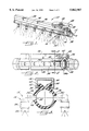
- FIG. 1 is an isometric view of a lightweight header according to the present invention
- FIG. 2 is another isometric view of the header of FIG. 1 shown without a plurality of spray nozzles;
- FIG. 3 is a cross-section view taken along the lines 3--3 of FIG. 2;
- FIG. 4 is an isometric view of a header according to a further embodiment of the invention.
- FIG. 5 is a cross-section view taken along the lines 5--5 of FIG. 4.
- the present invention relates to a manifold or header which supports and supplies fluid to a plurality of spaced spray nozzles in a liquid spray system.
- the header is of a relatively lightweight construction and includes one or more longitudinally extending flanges which provide planar surfaces for installation of the spray nozzles.
- FIG. 1 illustrates a longitudinally extending header or manifold 10 according to the present invention.
- the header 10 is adapted to receive fluid from a supply source in a direction denoted by an arrow 12 and transfer the fluid to a plurality of transverse fluid passageways such as passageway 14.
- the transverse passageways are located at predetermined spaced intervals along the length of the header 10.
- the transverse passageways each support spaced spray nozzle assemblies such as nozzle assembly 16, a cross section of which is shown in phantom FIG. 3.
- the nozzles 16 are each of a conventional type that are adapted to apply a liquid spray to a desired area. It will be understood by those skilled in the art that such mounting of spray nozzles can be utilized in various installations, such as stationary industrial spraying systems and the like.
- the illustrated nozzle assemblies such as nozzle assembly 16 include a downwardly oriented generally cylindrical body portion 18 that includes a bore formed on its peripheral side adapted to receive the transverse passageway 14.
- a cap portion 20 is sized to interfit with the body portion and receive a nozzle spray tip 22 at one of its ends. It will be appreciated that pressurized fluid introduced into the header 10 may supply fluid to a plurality of such interconnected nozzle assemblies 16, with the fluid passing through the transverse passageway 14 associated with each nozzle assembly and downwardly through the vertically depending body portion 18 for discharge through the nozzle spray tip 22.
- the header 10 comprises a longitudinally extending manifold or header body 24 that defines a generally tubular inner wall 26 (FIG. 3).
- the header body 24 is fabricated of a relatively lightweight, non-metallic material.
- a plastic extruded material such as a polypropylene may be utilized.
- the diameter of the inner wall 26 is preferably selected to be greater than that of conventional metal pipe now used for spraying application headers. This construction advantageously permits easy servicing and installation of the header 10.
- the material utilized further offers resistance to corrosive attack and even premature failure due to the handling of various chemicals or cleaning solutions which may be sprayed.
- header body For connecting the header body to further components of a spraying system, means are disposed at the ends of the header body for enabling ready connection of other components to the header. That is, internal threads such as threads 28 shown in FIG. 2 may be readily formed in the internal wall at a header body end 24e. This avoids complicated machining operations to be performed on the exterior of the header body in order to provide connection for upstream components with the header.
- a suitable socket arrangement such as the socket assembly 30 shown in FIG. 1 may include an outwardly extending conduit 32 that is glued within the header body end 24e.
- one or more flanges are formed on the outer peripheral surface of the header body.
- Each of the flanges presents a relatively planar surface to enable ready installation and removal of the nozzle assemblies supported by the header.
- flanges may be formed opposite to each other on the outer surface of the header body that are adapted to present exposed, relatively planar side surfaces.
- the flanges provide structural support for the header.
- the header includes opposed ribs or flanges 34, 36 extending outwardly along the length of the header body 24 to form lateral sides thereof.
- the ribs 34, 36 present a relatively planar opposed side surfaces 34s, 36s. This facilitates machining operations to the header body and securement of the nozzle assemblies or other components to the lateral sides of the header.
- a plurality of spaced openings such as opening 38 are formed in the ribs at predetermined locations along the length of the header body.
- the openings such as opening 38 are each sized to receive a plurality of nozzle assemblies such as nozzle assembly 16.
- the opening may include threads such as threads 40 in order to facilitate connection of the transverse passageways associated with the plurality of nozzles.
- the header body 24 includes a pair of opposed ears 42, 44 which are integrally formed with and extend outwardly from the outer peripheral surface of the header body 24.
- the header 10 is supported by a longitudinally extending metal channel support 46 having a generally C-shaped cross section.
- the channel support 46 may be attached to a ceiling or surface 48 with the use of screws such as the screw 50 shown in FIG. 1 or other suitable connecting means.
- the channel support 46 includes complementary flanges 52, 54 which form a channel that receives the ears 42, 44 in mated engagement when the header 10 is slidingly engaged with the channel support 46.
- a header body 124 is adapted to be slidingly received within a longitudinally extending channel support 146.
- a pair of outwardly facing ears 142, 144 integrally formed in the header body 124 extend along the length of the body 124.
- the channel support 146 is generally C-shaped, but it provides opposed spaced pairs of flanges 152a-b, 154a-b that each define opposed longitudinally extending grooves 156, 158.
- the opposed ears 142, 144 are sandwiched between the respective pairs of flanges 152a-b, 154a-b to secure the header 110 in place.
- the header body 124 is fabricated of a non-metallic material such as extruded plastic and includes a pair of opposed ribs 134, 136 which provide relatively flat side surfaces 134s, 136s for ready access by a plurality of nozzle assemblies.
- the body provides a generally cylindrical inner surface 126 that is preferably larger than conventional designs. This arrangement permits the ends of the header such as end 124e to be a female connection for other components of the spraying system.
- the header body 124 shown in FIGS. 4 and 5 includes a flange or rib 137 extending along the length of the header body 124 and formed on the underside thereof.
- the flange 137 includes a relatively flat surface 137s which provides a further location for attachment of spray nozzle assemblies.
- in-line or straight-through type nozzle assemblies may be located at spaced locations along the flange 137.
- flanges may alternatively be disposed at other orientations depending on the desired alignment and application of the spray nozzle assemblies being utilized.
- the header may be fabricated such that each of a pair of flanges are offset approximately 45 degrees from the orientation of the flanges 34, 36 shown in FIGS. 1 through 3 such that they provide somewhat downwardly facing surfaces.
- Other flange orientations may be utilized as desired.
- the header supplies fluid to a plurality of spaced apart nozzles in a relatively lightweight construction. This is accomplished with a tubular structure having opposed ribs that extend longitudinally from the lateral sides of the header body.
- the header body includes opposed ears that adapted to be received within a channel support. While the invention is susceptible of various modifications and alternative constructions, certain illustrative embodiments thereof have been shown and described above. It should be understood by those skilled in the art, however, that various modifications and alternative constructions and equivalents may be made without departing from the spirit and scope of the invention which is defined by the appended claims.
Landscapes
- Life Sciences & Earth Sciences (AREA)
- Engineering & Computer Science (AREA)
- Insects & Arthropods (AREA)
- Pest Control & Pesticides (AREA)
- Wood Science & Technology (AREA)
- Zoology (AREA)
- Environmental Sciences (AREA)
- Nozzles (AREA)
- Spray Control Apparatus (AREA)
Priority Applications (5)
| Application Number | Priority Date | Filing Date | Title |
|---|---|---|---|
| US08/844,301 US5862987A (en) | 1997-04-18 | 1997-04-18 | Non-metallic spray nozzle manifold and support therefor |
| EP98915391A EP0983121A4 (en) | 1997-04-18 | 1998-04-08 | NON-METAL DISTRIBUTOR FOR SPRAY NOZZLES AND HOLDING DEVICE FOR THIS DISTRIBUTOR |
| CA002287268A CA2287268A1 (en) | 1997-04-18 | 1998-04-08 | Non-metallic spray nozzle manifold and support therefor |
| PCT/US1998/007043 WO1998047624A1 (en) | 1997-04-18 | 1998-04-08 | Non-metallic spray nozzle manifold and support therefor |
| BR9808565-4A BR9808565A (pt) | 1997-04-18 | 1998-04-08 | Tubulação não metálica de bocal para pulverização e suporte para a mesma |
Applications Claiming Priority (1)
| Application Number | Priority Date | Filing Date | Title |
|---|---|---|---|
| US08/844,301 US5862987A (en) | 1997-04-18 | 1997-04-18 | Non-metallic spray nozzle manifold and support therefor |
Publications (1)
| Publication Number | Publication Date |
|---|---|
| US5862987A true US5862987A (en) | 1999-01-26 |
Family
ID=25292333
Family Applications (1)
| Application Number | Title | Priority Date | Filing Date |
|---|---|---|---|
| US08/844,301 Expired - Fee Related US5862987A (en) | 1997-04-18 | 1997-04-18 | Non-metallic spray nozzle manifold and support therefor |
Country Status (5)
| Country | Link |
|---|---|
| US (1) | US5862987A (pt) |
| EP (1) | EP0983121A4 (pt) |
| BR (1) | BR9808565A (pt) |
| CA (1) | CA2287268A1 (pt) |
| WO (1) | WO1998047624A1 (pt) |
Cited By (20)
| Publication number | Priority date | Publication date | Assignee | Title |
|---|---|---|---|---|
| US6269823B1 (en) * | 1998-05-04 | 2001-08-07 | Eagle-Picher Industries, Inc. | Can washing apparatus with plastic risers |
| US20050035225A1 (en) * | 2003-03-27 | 2005-02-17 | Spraying Systems Co. | Modular automatic spray gun manifold |
| US20050183866A1 (en) * | 2003-12-22 | 2005-08-25 | Patrick Gilson | Apparatus and method for transporting a transport medium |
| FR2870141A1 (fr) * | 2004-05-12 | 2005-11-18 | Bobard Jeune Soc Par Actions S | Elements de descente pour rampe de pulverisation |
| US7114667B1 (en) * | 2001-11-06 | 2006-10-03 | Bontems Thomas A | Nozzle coupling |
| US20070040051A1 (en) * | 2005-08-22 | 2007-02-22 | Goss International Americas, Inc. | Spray pattern valve body |
| US20070044670A1 (en) * | 2005-08-23 | 2007-03-01 | Goss International Americas, Inc. | Spray bar control for accomodating multiple widths |
| US20070045453A1 (en) * | 2005-08-23 | 2007-03-01 | Goss International Americas, Inc. | Central manifold supply for spray bar |
| FR2892893A1 (fr) * | 2005-11-04 | 2007-05-11 | Gerard Balespouey | Pulverisateur de produits de traitement sur des cultures |
| US20100096476A1 (en) * | 2001-06-01 | 2010-04-22 | Lindsay Corporation | Distribution tube assembly for irrigation |
| US7823800B1 (en) * | 2005-01-31 | 2010-11-02 | Jeff Kalpakoff | Misting system |
| US7837131B2 (en) | 2003-03-27 | 2010-11-23 | Spraying Systems Co. | Modular automatic spray gun manifold |
| US20130263789A1 (en) * | 2012-04-10 | 2013-10-10 | ChickenWaterer.com, LLC | Portable nipple based poultry waterer |
| US20180221894A1 (en) * | 2017-02-08 | 2018-08-09 | Oem Group, Llc | Adjustable flow nozzle system |
| USD854652S1 (en) * | 2017-07-31 | 2019-07-23 | Specialized Pavement Marking, Inc. | Ribbon application bar |
| BE1026059B1 (nl) * | 2018-02-28 | 2019-09-30 | Aquadraat Engineering Bvba | Kunststoffen buis die is aangepast voor een starre ophanging ervan en werkwijze voor het aanpassen van een kunststoffen buis in functie van een starre ophanging ervan |
| WO2020159969A1 (en) | 2019-01-28 | 2020-08-06 | Oem Group, Llc | Adjustable flow nozzle system |
| US20210051943A1 (en) * | 2019-08-21 | 2021-02-25 | Cnh Industrial America Llc | Agricultural Vehicle Having An Improved Application Boom For Mounting Attachments |
| US10994290B2 (en) | 2019-03-20 | 2021-05-04 | Cnh Industrial America Llc | Spray system with rail mounting for an agricultural machine |
| US11408694B2 (en) * | 2020-03-19 | 2022-08-09 | Saudi Arabian Oil Company | Reciprocating spray cleaning system for air-cooled heat exchangers |
Families Citing this family (1)
| Publication number | Priority date | Publication date | Assignee | Title |
|---|---|---|---|---|
| WO2012087859A1 (en) * | 2010-12-23 | 2012-06-28 | Agco Corporation | Nozzle spacing in a crop sprayer system |
Citations (6)
| Publication number | Priority date | Publication date | Assignee | Title |
|---|---|---|---|---|
| US3831681A (en) * | 1973-07-23 | 1974-08-27 | Factory Mutual Res Corp | Fire protection system utilizing modular components |
| US4753196A (en) * | 1986-08-06 | 1988-06-28 | Agri Manufacturing Corp. | Animal watering apparatus and method |
| US4834186A (en) * | 1987-10-19 | 1989-05-30 | Ballard Estus E | Sprinkler head mounting system |
| US5097798A (en) * | 1989-11-22 | 1992-03-24 | Little Larry L | Fowl watering system |
| US5230302A (en) * | 1990-10-17 | 1993-07-27 | Val Products, Inc. | Watering system for poultry, small animals and the like |
| US5651502A (en) * | 1995-03-14 | 1997-07-29 | Mistech, Inc. | Produce mister |
Family Cites Families (4)
| Publication number | Priority date | Publication date | Assignee | Title |
|---|---|---|---|---|
| FR1084256A (fr) * | 1953-06-04 | 1955-01-18 | Perfectionnements aux rampes d'arrosage | |
| US3091401A (en) * | 1962-02-19 | 1963-05-28 | Rain Jet Corp | Sprinkling system |
| US4273286A (en) * | 1977-11-29 | 1981-06-16 | Ris Irrigation Systems | Conduit for drip irrigation systems |
| US6269823B1 (en) * | 1998-05-04 | 2001-08-07 | Eagle-Picher Industries, Inc. | Can washing apparatus with plastic risers |
-
1997
- 1997-04-18 US US08/844,301 patent/US5862987A/en not_active Expired - Fee Related
-
1998
- 1998-04-08 WO PCT/US1998/007043 patent/WO1998047624A1/en not_active Application Discontinuation
- 1998-04-08 EP EP98915391A patent/EP0983121A4/en not_active Withdrawn
- 1998-04-08 CA CA002287268A patent/CA2287268A1/en not_active Abandoned
- 1998-04-08 BR BR9808565-4A patent/BR9808565A/pt not_active Application Discontinuation
Patent Citations (6)
| Publication number | Priority date | Publication date | Assignee | Title |
|---|---|---|---|---|
| US3831681A (en) * | 1973-07-23 | 1974-08-27 | Factory Mutual Res Corp | Fire protection system utilizing modular components |
| US4753196A (en) * | 1986-08-06 | 1988-06-28 | Agri Manufacturing Corp. | Animal watering apparatus and method |
| US4834186A (en) * | 1987-10-19 | 1989-05-30 | Ballard Estus E | Sprinkler head mounting system |
| US5097798A (en) * | 1989-11-22 | 1992-03-24 | Little Larry L | Fowl watering system |
| US5230302A (en) * | 1990-10-17 | 1993-07-27 | Val Products, Inc. | Watering system for poultry, small animals and the like |
| US5651502A (en) * | 1995-03-14 | 1997-07-29 | Mistech, Inc. | Produce mister |
Cited By (31)
| Publication number | Priority date | Publication date | Assignee | Title |
|---|---|---|---|---|
| US6269823B1 (en) * | 1998-05-04 | 2001-08-07 | Eagle-Picher Industries, Inc. | Can washing apparatus with plastic risers |
| US20100096476A1 (en) * | 2001-06-01 | 2010-04-22 | Lindsay Corporation | Distribution tube assembly for irrigation |
| US7114667B1 (en) * | 2001-11-06 | 2006-10-03 | Bontems Thomas A | Nozzle coupling |
| US20050035225A1 (en) * | 2003-03-27 | 2005-02-17 | Spraying Systems Co. | Modular automatic spray gun manifold |
| US7083121B2 (en) * | 2003-03-27 | 2006-08-01 | Spraying Systems Co. | Modular automatic spray gun manifold |
| US7837131B2 (en) | 2003-03-27 | 2010-11-23 | Spraying Systems Co. | Modular automatic spray gun manifold |
| US20050183866A1 (en) * | 2003-12-22 | 2005-08-25 | Patrick Gilson | Apparatus and method for transporting a transport medium |
| FR2870141A1 (fr) * | 2004-05-12 | 2005-11-18 | Bobard Jeune Soc Par Actions S | Elements de descente pour rampe de pulverisation |
| US7823800B1 (en) * | 2005-01-31 | 2010-11-02 | Jeff Kalpakoff | Misting system |
| US20070040051A1 (en) * | 2005-08-22 | 2007-02-22 | Goss International Americas, Inc. | Spray pattern valve body |
| US7793588B2 (en) | 2005-08-22 | 2010-09-14 | Goss International Americas, Inc. | Spray pattern valve body |
| US20070044670A1 (en) * | 2005-08-23 | 2007-03-01 | Goss International Americas, Inc. | Spray bar control for accomodating multiple widths |
| US20070045453A1 (en) * | 2005-08-23 | 2007-03-01 | Goss International Americas, Inc. | Central manifold supply for spray bar |
| US20080307988A1 (en) * | 2005-08-23 | 2008-12-18 | Goss International Americas, Inc. | Central manifold supply for spray bar |
| FR2892893A1 (fr) * | 2005-11-04 | 2007-05-11 | Gerard Balespouey | Pulverisateur de produits de traitement sur des cultures |
| US20130263789A1 (en) * | 2012-04-10 | 2013-10-10 | ChickenWaterer.com, LLC | Portable nipple based poultry waterer |
| US9265231B2 (en) * | 2012-04-10 | 2016-02-23 | ChickenWaterer.com, LLC | Portable nipple based poultry waterer |
| US11071989B2 (en) * | 2017-02-08 | 2021-07-27 | OEM Group East, LLC | Adjustable flow nozzle system |
| US20180221894A1 (en) * | 2017-02-08 | 2018-08-09 | Oem Group, Llc | Adjustable flow nozzle system |
| WO2018148448A1 (en) * | 2017-02-08 | 2018-08-16 | Oem Group, Llc | Adjustable flow nozzle system |
| US11623229B2 (en) | 2017-02-08 | 2023-04-11 | Shellback Semiconductor Technology, Llc | Adjustable flow nozzle system |
| USD854652S1 (en) * | 2017-07-31 | 2019-07-23 | Specialized Pavement Marking, Inc. | Ribbon application bar |
| BE1026059B1 (nl) * | 2018-02-28 | 2019-09-30 | Aquadraat Engineering Bvba | Kunststoffen buis die is aangepast voor een starre ophanging ervan en werkwijze voor het aanpassen van een kunststoffen buis in functie van een starre ophanging ervan |
| WO2020174269A1 (en) * | 2018-02-28 | 2020-09-03 | Aquadraat Engineering Bvba | Plastic tube adapted to a rigid suspension and method to adapt a plastic tube for a rigid suspension |
| US11207697B2 (en) | 2019-01-28 | 2021-12-28 | Shellback Semiconductor Technology, Llc | Adjustable flow nozzle system |
| EP3956067A4 (en) * | 2019-01-28 | 2022-11-09 | Shellback Semiconductor Technology, LLC | ADJUSTABLE FLOW NOZZLE SYSTEM |
| WO2020159969A1 (en) | 2019-01-28 | 2020-08-06 | Oem Group, Llc | Adjustable flow nozzle system |
| US10994290B2 (en) | 2019-03-20 | 2021-05-04 | Cnh Industrial America Llc | Spray system with rail mounting for an agricultural machine |
| US20210051943A1 (en) * | 2019-08-21 | 2021-02-25 | Cnh Industrial America Llc | Agricultural Vehicle Having An Improved Application Boom For Mounting Attachments |
| US11553705B2 (en) * | 2019-08-21 | 2023-01-17 | Cnh Industrial America Llc | Agricultural vehicle having an improved application boom for mounting attachments |
| US11408694B2 (en) * | 2020-03-19 | 2022-08-09 | Saudi Arabian Oil Company | Reciprocating spray cleaning system for air-cooled heat exchangers |
Also Published As
| Publication number | Publication date |
|---|---|
| BR9808565A (pt) | 2000-05-23 |
| CA2287268A1 (en) | 1998-10-29 |
| EP0983121A1 (en) | 2000-03-08 |
| WO1998047624A1 (en) | 1998-10-29 |
| EP0983121A4 (en) | 2000-07-19 |
Similar Documents
| Publication | Publication Date | Title |
|---|---|---|
| US5862987A (en) | Non-metallic spray nozzle manifold and support therefor | |
| US10406551B2 (en) | Spray nozzle mounting for receiving fluid from distribution pipe | |
| US6929032B2 (en) | Manifold | |
| US7591446B2 (en) | Swivel bracket system | |
| US5456499A (en) | Hull fitting | |
| US6058975A (en) | Connection member of water control valve | |
| US4708374A (en) | Plastic Tee fitting | |
| KR101195280B1 (ko) | 삽입형 배관용 연결장치 | |
| US3270966A (en) | Sprayer nozzle | |
| JPH06296651A (ja) | オーバーヘッドサポート | |
| KR930004673A (ko) | 파이프와 배관 및 그 파이프 고정 방법 | |
| WO2001085260A1 (en) | Threadless sprinkler head assembly | |
| US5209440A (en) | Hexagonal junction adapter with retaining shoulder | |
| US4695019A (en) | Non-metallic strut system | |
| US6508441B1 (en) | Sway brace | |
| US4549751A (en) | Universal support for meters | |
| US20140110934A1 (en) | Fluid-tight flexural joint | |
| US6648375B1 (en) | Pilot insert seal for a tube fitting | |
| US20070182156A1 (en) | Self-sealing fluid fitting and method | |
| US6082397A (en) | Gas manifold connector and gas distribution manifold assembly for gas stove | |
| US6112640A (en) | Cylinder | |
| EP2580029B1 (en) | A tool flange for an industrial robot | |
| CN111594515A (zh) | 安装方便的两通连接件 | |
| US5772256A (en) | Pipe support system | |
| US20200096138A1 (en) | Converter bulkhead fitting |
Legal Events
| Date | Code | Title | Description |
|---|---|---|---|
| AS | Assignment |
Owner name: SPRAYING SYSTEMS CO., ILLINOIS Free format text: ASSIGNMENT OF ASSIGNORS INTEREST;ASSIGNOR:REIF, STEPHEN C.;REEL/FRAME:008557/0824 Effective date: 19970415 |
|
| REMI | Maintenance fee reminder mailed | ||
| LAPS | Lapse for failure to pay maintenance fees | ||
| LAPS | Lapse for failure to pay maintenance fees |
Free format text: PATENT EXPIRED FOR FAILURE TO PAY MAINTENANCE FEES (ORIGINAL EVENT CODE: EXP.); ENTITY STATUS OF PATENT OWNER: LARGE ENTITY |
|
| STCH | Information on status: patent discontinuation |
Free format text: PATENT EXPIRED DUE TO NONPAYMENT OF MAINTENANCE FEES UNDER 37 CFR 1.362 |
|
| FP | Lapsed due to failure to pay maintenance fee |
Effective date: 20030126 |