US5857538A - Motorcycle - Google Patents
Motorcycle Download PDFInfo
- Publication number
- US5857538A US5857538A US08/792,157 US79215797A US5857538A US 5857538 A US5857538 A US 5857538A US 79215797 A US79215797 A US 79215797A US 5857538 A US5857538 A US 5857538A
- Authority
- US
- United States
- Prior art keywords
- engine
- motorcycle
- transmission
- backbone
- rigidly connected
- Prior art date
- Legal status (The legal status is an assumption and is not a legal conclusion. Google has not performed a legal analysis and makes no representation as to the accuracy of the status listed.)
- Expired - Lifetime
Links
Images


Classifications
-
- B—PERFORMING OPERATIONS; TRANSPORTING
- B62—LAND VEHICLES FOR TRAVELLING OTHERWISE THAN ON RAILS
- B62K—CYCLES; CYCLE FRAMES; CYCLE STEERING DEVICES; RIDER-OPERATED TERMINAL CONTROLS SPECIALLY ADAPTED FOR CYCLES; CYCLE AXLE SUSPENSIONS; CYCLE SIDECARS, FORECARS, OR THE LIKE
- B62K25/00—Axle suspensions
- B62K25/04—Axle suspensions for mounting axles resiliently on cycle frame or fork
- B62K25/28—Axle suspensions for mounting axles resiliently on cycle frame or fork with pivoted chain-stay
- B62K25/283—Axle suspensions for mounting axles resiliently on cycle frame or fork with pivoted chain-stay for cycles without a pedal crank, e.g. motorcycles
-
- B—PERFORMING OPERATIONS; TRANSPORTING
- B62—LAND VEHICLES FOR TRAVELLING OTHERWISE THAN ON RAILS
- B62K—CYCLES; CYCLE FRAMES; CYCLE STEERING DEVICES; RIDER-OPERATED TERMINAL CONTROLS SPECIALLY ADAPTED FOR CYCLES; CYCLE AXLE SUSPENSIONS; CYCLE SIDECARS, FORECARS, OR THE LIKE
- B62K11/00—Motorcycles, engine-assisted cycles or motor scooters with one or two wheels
- B62K11/02—Frames
- B62K11/04—Frames characterised by the engine being between front and rear wheels
Definitions
- the invention relates to motorcycles.
- the invention relates to the American motorcycle type of motorcycle having a relatively long wheelbase, low seat height, similar in size and shape, and engine type, to Harley-Davidson motorcycles manufactured by Harley-Davidson, Inc.
- a motorcycle similar to a Harley-Davidson motorcycle that has a very rigid frame that does not twist and flex appreciably while rapidly accelerating and turning at high speeds of sixty miles per hour and greater. Both front and rear wheels remain in close alignment during acceleration and at high speeds for improved performance, when traveling in a straight line and when turning.
- the motorcycle of the present invention can utilize radial tires to enhance stability of the motorcycle at high speeds.
- the motorcycle of the invention has the engine drive sprocket and the transmission driven sprocket on the left side of the motorcycle, and the drive chain, drive chain sprocket and transmission drive gear mounted on the right side of the motorcycle.
- a hard steel shaft runs through a machined connection cylinder rigidly connected to the mainframe of the motorcycle.
- the swingarms supporting the rear wheel of the motorcycle pivot about the steel shaft and the powertrain is bolted to this same steel shaft.
- the transmission is separate from the engine and drives a chain drive to the rear wheel on the right side of the motorcycle, and the distance between the driven shaft of the transmission and the drive shaft of the engine minimized, providing the strength and flex resistance to absorb large quantities of torque and horsepower because of the capability of providing both greater housing support at the drive shaft's outermost point and an outermost bearing support system as well.
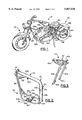
- FIG. 1 is a perspective view of the motorcycle of the invention from the left side;
- FIG. 2 is a perspective view of the mainframe of the invention taken from the left side;
- FIG. 3 is a perspective view of the centering apparatus of seat support assembly of the invention.
- FIG. 4 is a perspective view of the rear suspension assembly of the invention.
- FIG. 5 is a partly cut-away perspective view of the left side of the motorcycle of the invention with the engine sprocket and transmission sprocket, and the cover therefore, removed showing the engine drive shaft and the transmission driven shaft;
- FIG. 6 is a partly cut-away perspective view of the right side of the motorcycle of the invention showing the transmission drive shaft with the cover therefore removed;
- FIG. 7 is a partly cut-away detailed perspective view of the engine drive sprocket and the transmission driven sprocket connected by a drive belt with the cover therefore removed;
- FIG. 8 is a perspective view of the housing and cover for the drive shaft sprocket and transmission sprocket housing and cover;
- FIG. 9 is a perspective view of the motorcycle of the invention from the right side
- FIG. 10 is a side elevational view of the motorcycle of the invention.
- FIG. 11 is a elevational view of the mainframe of the invention taken from the right side with some components removed.
- FIGS. 1, 9, and 10 the improved motorcycle of the invention generally indicated by the numeral 10.
- the chain 11 driving the rear wheel 58 can be seen to be located on the right side of motorcycle 10.
- motorcycle 10 has an extremely rigid mainframe generally indicated by the numeral 20.
- the backbone generally indicated by the numeral 22 is a hollow steel tube preferably about three inches in outside diameter and has a wall thickness of 0.125 inches.
- Backbone 22 has a generally horizontal portion 22a and a generally vertical portion 22b bent downward at an obtuse angle from horizontal portion 22a.
- Vertical portion 22b is preferably integrally formed with horizontal portion 22a.
- Backbone 22 has a hollow, generally cylindrical steering head 24 rigidly welded thereto for rotating receipt of the front wheel assembly generally indicated by the numeral 26.
- connection cylinder 22d Rigidly connected to vertical portion 22b of backbone 22 is connection cylinder 22d shown in FIGS. 2, 5, 6, and 11.
- Connection cylinder 22d is preferably machined from a metal billet, preferably an alloy of steel and chromium such as 4130 Chromoly, and is preferably welded to vertical portion 22b.
- Connection cylinder 22d has a wall thickness of 0.25 inch and is adapted to receive a cylindrical shaft 23 shown in FIG. 6 and 10.
- Mainframe 20 has a steel engine support assembly generally indicated by the numeral 30.
- Engine support assembly 30 has a generally vertical hollow downtube 32 which is welded at its upper end to backbone 22 and steering head 24.
- Downtube 32 is preferably two inches in outside diameter and has a wall thickness of 0.095 inches.
- brace 25 is welded to portion 32 and portion 22a for additional strength and rigidity of mainframe 20.
- Downtube 32 has engine support assembly 30 connected thereto.
- Engine support assembly 30 includes a generally horizontal cradle 34 rigidly welded to downtube 32 at the lower end thereof to which the crankcase 28c of engine 28 is bolted to at plate 35a of bracket 35, bracket 35 having a generally vertical section 35b rigidly connected to generally horizontal plate 35a and generally horizontal plate 35c. Plate 35c is bolted to brace 34c.
- Engine crankcase 28c is also bolted to member 34d.
- Cradle 34 preferably has two hollow generally horizontal spaced-apart members 34a. and 34b welded at the rear end thereof to the lower end of vertical portion 22b of backbone 20.
- members 34a and 34b are about one and one-fourth inches in outside diameter and have a wall thickness of about 0.095 inches.
- a brace 34c is preferably welded between members 34a and 34b for additional strength and rigidity.
- the seat support assembly can best be seen in FIG. 3 generally indicated by the numeral 40.
- Seat support assembly 40 includes two spaced-apart parallel generally vertical members 40a and 40b which are rotatably connected at their lower ends 40c and 40d to threaded cylinder 22e on portion 22b of backbone 22 and at their upper ends to horizontal connecting member 40e.
- Seat support assembly 40 has a generally triangular seat support frame generally indicated by the numeral 42 for connection to seat 44.
- Seat support assembly has a threaded connection cylinder 42a at the front end thereof for connection to brackets 22c--22c on portion 22b of backbone 22.
- the rear wheel support assembly is a conventional rear wheel support assembly as can best be seen in FIG. 4 and is generally indicated by the numeral 50.
- Assembly 50 has two parallel swingarms 52 and 54 which are rotatably connected by hollow sleeves or cylinders 52a and 54a to connection cylinder 22d on portion 22b of backbone 22 shown in FIG. 3 and 11 to lock the mainframe 20 and backbone 22 to the swingarms 52 and 54, and two conventional shock absorbers 53--53 having springs 53a thereon are rigidly connected to connection cylinder 53b on the vertical portion 22b of backbone 22 and to connection cylinder 53c which is connected to member 64.
- the axle 57 of rear wheel 58 is received in slots 52b and 54b in swingarms 52 and 54, respectively.
- Rear fender 59 is rigidly connected to conventional swingarms 52 and 54 by members 60--60, 62--62, and 64.
- Engine 28 is rigidly connected to cradle 34 by bolting or the like.
- Engine 28 has two cylinders 28a and 28b connected to a crankcase 28c and is preferably air-cooled four-cycle engine made by S&S Cycle Inc., Box 215, Route 2, County G, Viola, WI 54664, having a bore of 91 millimeters, a stroke of 114 millimeters, with a resultant displacement of 93 cubic inches.
- Engine 28 has a drive shaft 28d extending therefrom which has a sprocket 28e connected thereto.
- a transmission 30 is located adjacent to crankcase 28c and has a drive shaft 30a and a sprocket 30b connected thereto. Transmission 30 is bolted to plate 35b and to drive guard 31.
- a belt 33 is connected to the outside of sprocket 28e and 30b to enable sprocket 28e to drive sprocket 30b.
- the transmission is separate from the engine and drives shaft 30c on the right side of motorcycle 10 having a conventional sprocket (not shown) attached thereto over which a chain 11 is fitted to drive the sprocket 13 on rear wheel 58 on the right side of motorcycle 10.
- Engine 28 preferably is connected at cylinders 28a and 28b to connection cylinder 22f on backbone 22 by members 22g and 22h.
- Primary drive guard 31 is preferably a one-piece housing machined from a billet of high strength metal alloy to provide a rigid connection of the transmission 30 bolted thereto in close proximity to engine crankcase 28c.
- Primary drive cover plate 31a is bolted to primary drive guard 31 to enclose sprockets 28e, 30b, and belt 32 and protect them from dirt, water, and the like.
- Primary drive guard 31 enables the transmission 30 to be rigidly located as close to engine crankcase 28c as possible to shorten the center to center distance between the motor and transmission sprockets 28e and 30b, providing the strength and flex resistance to absorb large quantities of torque and horsepower because of the capability of providing both greater housing support at the drive shaft's outermost point and an outermost bearing support system as well.
- the distance between engine drive shaft 28d and transmission drive shaft 30a is about nine inches.
- an approximately 1/2 inch thick plate 70 best seen in FIG. 10 is bolted to transmission 30 on the right side of motorcycle 10 and to the outside of swingarm 52 at 52a on connection cylinder 22d on member 22b of mainframe 20.
- the outside diameter of cylinder 22d is about two inches to insure alignment of rear wheel assembly 50 with mainframe 20, and to provide a rigid connection of transmission 30 to backbone 22.
- the mainframe 20 can be seen to closely conform to the outside of the engine 28 and transmission 30. Such an arrangement increases the rigidity of mainframe 20 and reduces twisting during acceleration and cornering at high speeds.
- the ratio of the distance between drive shafts 28d and 30a and the distance between members 32 and 22b along the plane including drive shafts 28d and 30a is important to achieve rigidity.
- connection cylinder 22d and downtube 32 along the plane including drive shafts 28d and 30a is about 20 inches.
- the ratio of the distance between drive shafts 28d and 30a and the distance between downtube 32 and connection cylinder 22d along the plane including drive shafts 28d and 30a is about 1:2. More, preferably, the ratio of the distance between drive shafts 28d and 30a and the distance between downtube 32 and connection tube 22d along the plane including drive shafts 28d and 30a is about 0.9:2; more preferably, about 0.8:2.
- the present invention provides a motorcycle having an extremely rigid one-piece mainframe 20 with an extremely rigid connection to the rear wheel assembly and front wheel assembly which provides a superior ride.
- Connecting the engine 28 rigidly and closely to transmission 30 first by a one piece housing 31 machined from a billet of high strength metal alloy and second by connecting the engine 28 and transmission 30 by a machined bracket 35 connected to brace 34d as shown in FIG. 2, and furthermore connecting the housing 31 to mainframe 20 at connection cylinder 22d and connecting the transmission 30 by machined plate 70 to the same connection cylinder 22d on backbone 22 to which the swingarms 52 and 54 are connected are believed to provide such rigid characteristics and superior ride of the motorcycle of the invention.
- the engine, transmission, and primary drive system design use standard components proven over millions of street miles yet comprised of heavy duty castings and internal components proven over thousands of passes and racing miles to withstand maximum performance capacity under the most over-stressed conditions.
- the transmission though traditional and proven in design, has been modified to shorten the center to center distance between the motor and transmission sprockets and to drive output on the right (other) side of the motorcycle, providing the strength and flex resistance to absorb huge quantities of torque and horsepower because of the capability of providing both greater housing support at the drive shaft's outermost point and an outermost bearing support system as well.
- the elongated rear suspension is of traditional British design including a cantilever system with a loop and triangulation system is used. Five and 1/4 inches of rear wheel travel is specified.
- the oil reservoir for the four cycle engine 28 is provided within the hollow backbone 22 and hollow downtube 32 which hold over six quarts. This innovation enables the provision in motorcycle 10 of a 26 1/2 inch seat height without compromising rear, wheel suspension travel or ground clearance. Oil is added to the oil reservoir through tube 22f shown in FIG. 2.
Landscapes
- Engineering & Computer Science (AREA)
- Mechanical Engineering (AREA)
- Automatic Cycles, And Cycles In General (AREA)
Abstract
Description
Claims (20)
Priority Applications (1)
| Application Number | Priority Date | Filing Date | Title |
|---|---|---|---|
| US08/792,157 US5857538A (en) | 1996-01-31 | 1997-01-30 | Motorcycle |
Applications Claiming Priority (2)
| Application Number | Priority Date | Filing Date | Title |
|---|---|---|---|
| US1089596P | 1996-01-31 | 1996-01-31 | |
| US08/792,157 US5857538A (en) | 1996-01-31 | 1997-01-30 | Motorcycle |
Publications (1)
| Publication Number | Publication Date |
|---|---|
| US5857538A true US5857538A (en) | 1999-01-12 |
Family
ID=26681722
Family Applications (1)
| Application Number | Title | Priority Date | Filing Date |
|---|---|---|---|
| US08/792,157 Expired - Lifetime US5857538A (en) | 1996-01-31 | 1997-01-30 | Motorcycle |
Country Status (1)
| Country | Link |
|---|---|
| US (1) | US5857538A (en) |
Cited By (28)
| Publication number | Priority date | Publication date | Assignee | Title |
|---|---|---|---|---|
| US6105548A (en) * | 1998-11-03 | 2000-08-22 | Briggs & Stratton Corporation | Mounting apparatus for an engine and transmission |
| US6142498A (en) * | 1998-12-11 | 2000-11-07 | Chrome Specialties, Inc. | Motorcycle frame |
| US6290017B1 (en) * | 1998-09-11 | 2001-09-18 | Honda Giken Kogyo Kabushiki Kaisha | Body frame structure of a two-wheeled motor vehicle |
| US6312000B1 (en) * | 1999-10-29 | 2001-11-06 | Sunrise Medical Hhg Inc. | Wheelchair fender and method of mounting wheelchair fender |
| US6315072B1 (en) * | 1999-07-29 | 2001-11-13 | Harley-Davidson Motor Company Group, Inc. | Motorcycle engine mounting assembly |
| US6446744B2 (en) * | 1998-12-23 | 2002-09-10 | Bombardier Inc. | Engine cradle for a vehicle |
| US20030164257A1 (en) * | 2002-03-02 | 2003-09-04 | William Soileau | Wide motorcycle swing arm assembly |
| US20040124029A1 (en) * | 2002-09-26 | 2004-07-01 | Honda Giken Kogyo Kabushiki Kaisha | Engine mounting structure of low floor type vehicle |
| US6866112B2 (en) * | 2001-07-09 | 2005-03-15 | Buell Motorcycle Company | Motorcycle having stationary belt tensioner |
| US6902023B2 (en) | 2003-07-11 | 2005-06-07 | Harley-Davidson Motor Company Group, Inc. | Engine mounting system for a motorcycle |
| KR100504625B1 (en) * | 2001-02-02 | 2005-08-01 | 혼다 기켄 고교 가부시키가이샤 | Engine for motor cycle |
| US20050236206A1 (en) * | 2001-06-20 | 2005-10-27 | Shidehiko Miyashiro | Motorcycle rear suspension swingarm assembly |
| US7048083B1 (en) * | 2002-07-12 | 2006-05-23 | Paradigm Technologies, L.L.P. | Motorcycle including a unique frame and drive unit |
| US20070012500A1 (en) * | 2005-03-02 | 2007-01-18 | Bbr Motorsports, Inc. | Motorcycle frame and motorcycle |
| US20070045025A1 (en) * | 2005-08-31 | 2007-03-01 | Honda Motor Co., Ltd. | Engine support structure of motorcycle |
| US20070272466A1 (en) * | 2006-05-26 | 2007-11-29 | Levey John R | Motorcycle with in-line radial engine |
| US20080277898A1 (en) * | 2007-05-10 | 2008-11-13 | Julia Chu | Reinforced motorcycle frame |
| US20090008179A1 (en) * | 2007-07-02 | 2009-01-08 | Erik Buell | Motorcycle having a rotatably-mounted engine |
| US20090065278A1 (en) * | 2007-05-11 | 2009-03-12 | White John L | Right side drive conversion |
| US20090166119A1 (en) * | 2007-12-28 | 2009-07-02 | Yamaha Hatsudoki Kabushiki Kaisha | Motorcycle |
| CN101412428B (en) * | 2008-12-09 | 2011-07-06 | 立峰集团有限公司 | Structure for connecting engine and body of two-wheeled straddle type motorcycle |
| US20110232987A1 (en) * | 2009-07-25 | 2011-09-29 | Chipp Gary D | Sub-frame and component configuration for mounting of a motorcycle drop seat |
| US20110303477A1 (en) * | 2010-06-09 | 2011-12-15 | Jose Luis Belil Creixell | Motorcycle |
| JP2014162425A (en) * | 2013-02-27 | 2014-09-08 | Honda Motor Co Ltd | Vehicle body frame for saddle-riding type vehicle |
| US9474667B1 (en) * | 2015-08-05 | 2016-10-25 | Jason Gruber | Wheelchair contamination shield with mounting system |
| US10513301B2 (en) * | 2016-05-05 | 2019-12-24 | Lyft, Inc. | Fender and fender assembly for a cycling apparatus |
| US11142284B2 (en) | 2018-07-30 | 2021-10-12 | Harley-Davidson Motor Company Group, LLC | Drive belt assembly for an electric vehicle |
| US12454333B2 (en) * | 2022-01-11 | 2025-10-28 | Bayerische Motoren Werke Aktiengesellschaft | Belt drive for driving a motor vehicle, in particular a motorcycle, and motor vehicle, in particular a motorcycle |
Citations (5)
| Publication number | Priority date | Publication date | Assignee | Title |
|---|---|---|---|---|
| US4280582A (en) * | 1976-11-01 | 1981-07-28 | Honda Giken Kogyo Kabushiki Kaisha | Vehicle frame arrangement in motorized two-wheeled vehicle |
| US4433747A (en) * | 1980-12-01 | 1984-02-28 | Sercati S.A.R.L. | Motorcycle with improved rear suspension |
| US5109943A (en) * | 1990-07-13 | 1992-05-05 | Crenshaw Rodney D | Motorcycle engine stabilizer |
| US5469930A (en) * | 1994-06-17 | 1995-11-28 | Harley-Davidson, Inc. | Motorcycle rear wheel suspension |
| US5775454A (en) * | 1996-07-09 | 1998-07-07 | Harley-Davidson Motor Company | Motorcycle with front fender mounting system |
-
1997
- 1997-01-30 US US08/792,157 patent/US5857538A/en not_active Expired - Lifetime
Patent Citations (5)
| Publication number | Priority date | Publication date | Assignee | Title |
|---|---|---|---|---|
| US4280582A (en) * | 1976-11-01 | 1981-07-28 | Honda Giken Kogyo Kabushiki Kaisha | Vehicle frame arrangement in motorized two-wheeled vehicle |
| US4433747A (en) * | 1980-12-01 | 1984-02-28 | Sercati S.A.R.L. | Motorcycle with improved rear suspension |
| US5109943A (en) * | 1990-07-13 | 1992-05-05 | Crenshaw Rodney D | Motorcycle engine stabilizer |
| US5469930A (en) * | 1994-06-17 | 1995-11-28 | Harley-Davidson, Inc. | Motorcycle rear wheel suspension |
| US5775454A (en) * | 1996-07-09 | 1998-07-07 | Harley-Davidson Motor Company | Motorcycle with front fender mounting system |
Non-Patent Citations (7)
| Title |
|---|
| American Iron Magazine; (USPS 007 321) (ISSN 1059 7891) Jul. 1992,vol. 4, No. 7 Published by Tam Communications, Inc.; p. 18. * |
| American Iron Magazine; (USPS 007 321) (ISSN 1059 7891) Jul. 1995, vol. 7 No. 7 Published by Tam Communications, Inc.; pp. 36; 85. * |
| American Iron Magazine; (USPS 007-321) (ISSN 1059-7891) Jul. 1992,vol. 4, No. 7 Published by Tam Communications, Inc.; p. 18. |
| American Iron Magazine; (USPS 007-321) (ISSN 1059-7891) Jul. 1995, vol. 7 No. 7 Published by Tam Communications, Inc.; pp. 36; 85. |
| Hot Bike; Apr. 1994, vol. 26, No. 4; Published by McMullen & Yee Publishing, Inc.; pp. 52, 53, 55, 108 and p. 114. * |
| Hot Bike; May 1992, vol. 24, No. 4; Published by McMullen & Yee Publishing Co., pp. 12 and 33. * |
| Hot Bike; May 1996, vol. 28, No. 5; Published by McMullen & Yee Publishing, Inc.; pp. 2, 13, 41, 133. * |
Cited By (42)
| Publication number | Priority date | Publication date | Assignee | Title |
|---|---|---|---|---|
| US6290017B1 (en) * | 1998-09-11 | 2001-09-18 | Honda Giken Kogyo Kabushiki Kaisha | Body frame structure of a two-wheeled motor vehicle |
| US6105548A (en) * | 1998-11-03 | 2000-08-22 | Briggs & Stratton Corporation | Mounting apparatus for an engine and transmission |
| US6142498A (en) * | 1998-12-11 | 2000-11-07 | Chrome Specialties, Inc. | Motorcycle frame |
| US20060108164A1 (en) * | 1998-12-23 | 2006-05-25 | Jerome Wubbolts | Snowmobile frame |
| US6446744B2 (en) * | 1998-12-23 | 2002-09-10 | Bombardier Inc. | Engine cradle for a vehicle |
| US6604594B2 (en) | 1998-12-23 | 2003-08-12 | Bombardier Inc. | Foot grip |
| US7451846B2 (en) | 1998-12-23 | 2008-11-18 | Bombardier Recreational Products Inc. | Snowmobile frame |
| US6315072B1 (en) * | 1999-07-29 | 2001-11-13 | Harley-Davidson Motor Company Group, Inc. | Motorcycle engine mounting assembly |
| US6312000B1 (en) * | 1999-10-29 | 2001-11-06 | Sunrise Medical Hhg Inc. | Wheelchair fender and method of mounting wheelchair fender |
| KR100504625B1 (en) * | 2001-02-02 | 2005-08-01 | 혼다 기켄 고교 가부시키가이샤 | Engine for motor cycle |
| US20050236206A1 (en) * | 2001-06-20 | 2005-10-27 | Shidehiko Miyashiro | Motorcycle rear suspension swingarm assembly |
| US7165301B2 (en) | 2001-06-20 | 2007-01-23 | Yamaha Hatsudoki Kabushiki Kaisha | Motorcycle rear suspension swingarm assembly |
| US6866112B2 (en) * | 2001-07-09 | 2005-03-15 | Buell Motorcycle Company | Motorcycle having stationary belt tensioner |
| US20030164257A1 (en) * | 2002-03-02 | 2003-09-04 | William Soileau | Wide motorcycle swing arm assembly |
| US7048083B1 (en) * | 2002-07-12 | 2006-05-23 | Paradigm Technologies, L.L.P. | Motorcycle including a unique frame and drive unit |
| US7360620B2 (en) * | 2002-09-26 | 2008-04-22 | Honda Giken Kogyo Kabushiki Kaisha | Engine mounting structure of low floor type vehicle |
| US20040124029A1 (en) * | 2002-09-26 | 2004-07-01 | Honda Giken Kogyo Kabushiki Kaisha | Engine mounting structure of low floor type vehicle |
| US20050178596A1 (en) * | 2003-07-11 | 2005-08-18 | Harley-Davidson Motor Company Group, Inc. | Engine mounting system for a motorcycle |
| US7201246B2 (en) | 2003-07-11 | 2007-04-10 | Harley-Davidson Motor Company Group, Inc. | Engine mounting system for a motorcycle |
| US6902023B2 (en) | 2003-07-11 | 2005-06-07 | Harley-Davidson Motor Company Group, Inc. | Engine mounting system for a motorcycle |
| US20070012500A1 (en) * | 2005-03-02 | 2007-01-18 | Bbr Motorsports, Inc. | Motorcycle frame and motorcycle |
| US20070045025A1 (en) * | 2005-08-31 | 2007-03-01 | Honda Motor Co., Ltd. | Engine support structure of motorcycle |
| US7503415B2 (en) * | 2005-08-31 | 2009-03-17 | Honda Motor Co., Ltd. | Engine support structure of motorcycle |
| US20070272466A1 (en) * | 2006-05-26 | 2007-11-29 | Levey John R | Motorcycle with in-line radial engine |
| US20080277898A1 (en) * | 2007-05-10 | 2008-11-13 | Julia Chu | Reinforced motorcycle frame |
| US20090065278A1 (en) * | 2007-05-11 | 2009-03-12 | White John L | Right side drive conversion |
| US20090008179A1 (en) * | 2007-07-02 | 2009-01-08 | Erik Buell | Motorcycle having a rotatably-mounted engine |
| US20090166119A1 (en) * | 2007-12-28 | 2009-07-02 | Yamaha Hatsudoki Kabushiki Kaisha | Motorcycle |
| US8037962B2 (en) * | 2007-12-28 | 2011-10-18 | Yamaha Hatsudoki Kabushiki Kaisha | Motorcycle |
| CN101412428B (en) * | 2008-12-09 | 2011-07-06 | 立峰集团有限公司 | Structure for connecting engine and body of two-wheeled straddle type motorcycle |
| US20160236740A1 (en) * | 2009-07-25 | 2016-08-18 | Gary D. Chipp | Sub-frame and component configuration for mounting of a motorcycle drop seat |
| US20110232987A1 (en) * | 2009-07-25 | 2011-09-29 | Chipp Gary D | Sub-frame and component configuration for mounting of a motorcycle drop seat |
| US9701353B2 (en) * | 2009-07-25 | 2017-07-11 | Gary D. Chipp | Sub-frame and component configuration for mounting of a motorcycle drop seat |
| US8616324B2 (en) * | 2009-07-25 | 2013-12-31 | Gary D. Chipp | Sub-frame and component configuration for mounting of a motorcycle drop seat |
| US8561746B2 (en) * | 2010-06-09 | 2013-10-22 | Jose Luis Belil Creixell | Motorcycle |
| US20110303477A1 (en) * | 2010-06-09 | 2011-12-15 | Jose Luis Belil Creixell | Motorcycle |
| JP2014162425A (en) * | 2013-02-27 | 2014-09-08 | Honda Motor Co Ltd | Vehicle body frame for saddle-riding type vehicle |
| US9474667B1 (en) * | 2015-08-05 | 2016-10-25 | Jason Gruber | Wheelchair contamination shield with mounting system |
| US10513301B2 (en) * | 2016-05-05 | 2019-12-24 | Lyft, Inc. | Fender and fender assembly for a cycling apparatus |
| US11230337B2 (en) | 2016-05-05 | 2022-01-25 | Lyft, Inc. | Fender and fender assembly for a cycling apparatus |
| US11142284B2 (en) | 2018-07-30 | 2021-10-12 | Harley-Davidson Motor Company Group, LLC | Drive belt assembly for an electric vehicle |
| US12454333B2 (en) * | 2022-01-11 | 2025-10-28 | Bayerische Motoren Werke Aktiengesellschaft | Belt drive for driving a motor vehicle, in particular a motorcycle, and motor vehicle, in particular a motorcycle |
Similar Documents
| Publication | Publication Date | Title |
|---|---|---|
| US5857538A (en) | Motorcycle | |
| EP0437776B1 (en) | Motorcycle | |
| CA2502056C (en) | All terrain vehicle | |
| CA2657101C (en) | Front wheel suspension structure for saddle-type vehicle, and vehicle incorporating same | |
| US5295702A (en) | Single sided cycle rear suspension system | |
| US5435584A (en) | Cycle rear suspension with shock absorber built into frame lug | |
| US5575352A (en) | Four-wheeled vehicle | |
| US20040140140A1 (en) | Three-wheeled vehicle having an oil cooler assembly | |
| NZ203181A (en) | Four wheeled motorcycle | |
| US6719084B2 (en) | Exhaust system for vehicular two-cylinder engine | |
| JP2008238995A (en) | Body frame structure | |
| EP1391373A1 (en) | Motorcycle body protecting device | |
| EP0532791B1 (en) | Detachable frame for motorcycle | |
| AU594707B2 (en) | Saddle type vehicle running on uneven ground | |
| US4756379A (en) | Motorcycle | |
| US20080223648A1 (en) | Body Frame of Motorcycle, Assembling Method of Mounting Engine on Body Frame, and Motorcycle Having Body Frame | |
| JP2020050306A (en) | Steering structure of saddle-riding type vehicle | |
| JP2621273B2 (en) | Fuel tank mounting structure for saddle type vehicles | |
| US7309081B1 (en) | Four wheel off-road vehicle | |
| JP2657661B2 (en) | Underbody structure of motorcycle | |
| CN100532186C (en) | motorcycle | |
| JPH08258781A (en) | bicycle | |
| JP2757183B2 (en) | Saddle-type vehicle | |
| JP3541656B2 (en) | Motorcycle with unit swing type engine | |
| JPH0418593B2 (en) |
Legal Events
| Date | Code | Title | Description |
|---|---|---|---|
| FEPP | Fee payment procedure |
Free format text: PAYOR NUMBER ASSIGNED (ORIGINAL EVENT CODE: ASPN); ENTITY STATUS OF PATENT OWNER: SMALL ENTITY |
|
| AS | Assignment |
Owner name: WEBBANK CORPORATION, UTAH Free format text: SECURITY INTEREST;ASSIGNOR:CONFEDERATE MOTORCYCLES, INC.;REEL/FRAME:009782/0106 Effective date: 19990210 |
|
| FPAY | Fee payment |
Year of fee payment: 4 |
|
| AS | Assignment |
Owner name: CONFEDERATE MOTOR COMPANY, INC., LOUISIANA Free format text: ASSIGNMENT OF ASSIGNORS INTEREST;ASSIGNOR:MILLER, PAMELA S.;REEL/FRAME:013852/0221 Effective date: 20010917 Owner name: PAMELA S. MILLER, LOUISIANA Free format text: ASSIGNMENT OF ASSIGNORS INTEREST;ASSIGNOR:CHAMBERS, H. MATHEW;REEL/FRAME:013852/0202 Effective date: 20010917 |
|
| AS | Assignment |
Owner name: CONFEDERATE MOTOROCYCLES, INC., LOUISIANA Free format text: ORDER APPROVING TRUSTEE'S PETITION OF DISCLAIMER A;ASSIGNOR:ADLER, DAVID, TRUSTEE IN BANKRUPTCY;REEL/FRAME:013879/0642 Effective date: 20030522 Owner name: BIZCAPITAL BUSINESS AND INDUSTRIAL DEVELOPMENT COR Free format text: SECURITY INTEREST;ASSIGNOR:CONFEDERATE MOTOR CO., LTD.;REEL/FRAME:013879/0639 Effective date: 20030812 |
|
| AS | Assignment |
Owner name: CONFEDERATE MOTORCYCLES, INC., LOUISIANA Free format text: CORRECTIVE ASSIGNMENT TO CORRECT THE INCORRECT PATENT NUMBER FROM 5,587, 538 TO 5, 857,538, DOCUMENT PREVIOULSY RECORDED AT REEL 013879 FRAME 0642;ASSIGNOR:TRUSTEE IN BANKRUPTCY, DAVID ADLER;REEL/FRAME:013887/0298 Effective date: 20030522 Owner name: BIZCAPITAL BUSINESS AND INDUSTRIAL DEVELOPMENT COR Free format text: SECURITY AGREEMENT DOCUMENT PREVIOUSLY RECORDED ON REEL 013879 FRAME 0639 CONTAINED AN ERROR IN PATENT NUMBER 5587538. DOCUMENT RERECORDED TO CORRECT ERROR ON STATED REEL.;ASSIGNOR:CONFEDERATE MOTOR CO., INC.;REEL/FRAME:013897/0724 Effective date: 20030812 Owner name: BIZCAPITAL BUSINESS AND INDUSTRIAL DEVELOPMENT COR Free format text: ASSIGNMENT OF ASSIGNORS INTEREST;ASSIGNOR:CONFEDERATE MOTOR CO., INC.;REEL/FRAME:013887/0295 Effective date: 20030812 |
|
| AS | Assignment |
Owner name: MILLER, PAMELA, LOUISIANA Free format text: ASSIGNMENT OF ASSIGNORS INTEREST;ASSIGNOR:CHAMBERS, H. MATTHEW;REEL/FRAME:015703/0248 Effective date: 20010917 |
|
| REMI | Maintenance fee reminder mailed | ||
| FEPP | Fee payment procedure |
Free format text: PETITION RELATED TO MAINTENANCE FEES FILED (ORIGINAL EVENT CODE: PMFP); ENTITY STATUS OF PATENT OWNER: SMALL ENTITY |
|
| FEPP | Fee payment procedure |
Free format text: PETITION RELATED TO MAINTENANCE FEES GRANTED (ORIGINAL EVENT CODE: PMFG); ENTITY STATUS OF PATENT OWNER: SMALL ENTITY |
|
| REIN | Reinstatement after maintenance fee payment confirmed | ||
| FPAY | Fee payment |
Year of fee payment: 8 |
|
| FP | Lapsed due to failure to pay maintenance fee |
Effective date: 20070112 |
|
| PRDP | Patent reinstated due to the acceptance of a late maintenance fee |
Effective date: 20070622 |
|
| STCF | Information on status: patent grant |
Free format text: PATENTED CASE |
|
| FPAY | Fee payment |
Year of fee payment: 12 |