US5844409A - Method and system for measuring an electric current with two light signals propagating in opposite directions, using the Faraday effect - Google Patents
Method and system for measuring an electric current with two light signals propagating in opposite directions, using the Faraday effect Download PDFInfo
- Publication number
- US5844409A US5844409A US08/624,440 US62444096A US5844409A US 5844409 A US5844409 A US 5844409A US 62444096 A US62444096 A US 62444096A US 5844409 A US5844409 A US 5844409A
- Authority
- US
- United States
- Prior art keywords
- signal
- signals
- intensity
- linearly polarized
- normalized
- Prior art date
- Legal status (The legal status is an assumption and is not a legal conclusion. Google has not performed a legal analysis and makes no representation as to the accuracy of the status listed.)
- Expired - Fee Related
Links
Images


Classifications
-
- G—PHYSICS
- G01—MEASURING; TESTING
- G01R—MEASURING ELECTRIC VARIABLES; MEASURING MAGNETIC VARIABLES
- G01R15/00—Details of measuring arrangements of the types provided for in groups G01R17/00 - G01R29/00, G01R33/00 - G01R33/26 or G01R35/00
- G01R15/14—Adaptations providing voltage or current isolation, e.g. for high-voltage or high-current networks
- G01R15/24—Adaptations providing voltage or current isolation, e.g. for high-voltage or high-current networks using light-modulating devices
- G01R15/245—Adaptations providing voltage or current isolation, e.g. for high-voltage or high-current networks using light-modulating devices using magneto-optical modulators, e.g. based on the Faraday or Cotton-Mouton effect
- G01R15/246—Adaptations providing voltage or current isolation, e.g. for high-voltage or high-current networks using light-modulating devices using magneto-optical modulators, e.g. based on the Faraday or Cotton-Mouton effect based on the Faraday, i.e. linear magneto-optic, effect
Definitions
- the present invention relates to a method and arrangement for measuring an electric current in a current conductor, in particular with the aid of a Faraday element assigned to the current conductor.
- Optical measuring arrangements are known for measuring an electric current in a current conductor, using the Faraday effect, which are also designated magneto-optic current transformers.
- the Faraday effect is understood the rotation of the plane of polarization of linearly polarized light as a function of a magnetic field.
- the angle of rotation is proportional to the path integral over the magnetic field along the path traced by the light with the so-called Verdet constant as the constant of proportionality.
- the Verdet constant is generally dependent on material, temperature and wavelength.
- a Faraday element made of an optically transparent material such as, for example, glass is arranged in the vicinity of the current conductor.
- the magnetic field generated by the current effects a rotation of the plane of polarization of linearly polarized light transmitted through the Faraday element by an angle of rotation which can be evaluated as a measured signal.
- the Faraday element surrounds the current conductor, so that the measuring light circulates around the current conductor in a closed path.
- the amount of the angle of rotation is in this case to a good approximation directly proportional to the amplitude of the current to be measured.
- the Faraday element can be designed as a solid glass ring around the current conductor as described in European Patent Application No. 0 088 419, or can also surround the current conductor in the form of a measuring winding made of a light-conducting monomode fiber (fiber coil).
- magneto-optic current transformer with respect to conventional inductive current transformers are its galvanic isolation and insensitivity with respect to electromagnetic disturbances.
- problems are presented by their temperature and vibration sensitivity.
- the Internation Patent Application No. 92/13280 discloses one embodiment of a magneto-optic current transformer having an optical fiber designed as a Faraday measuring winding around the current conductor.
- an optical fiber with a high intrinsic circular birefringence ⁇ 0 compared with the Faraday rotation, in conjunction with suitably selected signal processing, vibration influences are largely compensated.
- the measuring principle in this known embodiment consists in transmitting into the fiber coil two linearly polarized light signals S and T propagating in opposite directions.
- Both light signals S and T after the passage through the Faraday element, are split into two partial light signals S1 and S2 or T1 and T2 with planes of polarization orthogonal to each other, and these partial light signals S1 and S2 or T1 and T2 are converted into corresponding electric intensity signals IS1 and IS2 or IT1 and IT2 with the aid of photodetectors.
- These four intensity signals IS1 and IS2 and IT1 and IT2 are divided by squares of the amplitudes, which correspond to the total intensity IS1+IS2 or IT1+IT2, and are thus intensity-normalized.
- the Faraday effect is a non-reciprocal effect, so that the two light signals S and T are rotated in the opposite sense of rotation, through the same Faraday angle ⁇ .
- the linear birefringence in the material of the fiber is, on the other hand, a reciprocal effect and, therefore, effects the same modulation of the two light signals S and T.
- the measured signal M formed with this known method is, to a good approximation, equal to ⁇ / ⁇ O and thus specifically still contains the information about the Faraday rotation ⁇ of the two light signals S and T and thus about the measured current, the disturbing linear birefringence effects, especially caused by vibrations of the fiber, are however, practically fully eliminated. Nevertheless, the measured signal M is dependent on the circular birefringence ⁇ O used as a calibration quantity and is thus, because of the dependence of the circular birefringence on the temperature, itself temperature dependant.
- the object of the present invention to specify a method and an arrangement for measuring an electric current, using the Faraday effect, in which both the vibration sensitivity and also the temperature sensitivity are largely suppressed.
- the present invention utilizes a method and a system where by using a Faraday element having a circular birefringence which is smaller in comparison to an obtained measured angle using the Faraday effect (with the Faraday rotation), and suitable signal processing means, a measured signal can be obtained which is largely independent both of vibrations and also of the temperature.
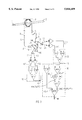
- FIG. 1 schematically illustrates an arrangement for measuring an electric current, according to a first embodiment of the present invention.
- FIG. 2 schematically illustrates a second embodiment of an arrangement for measuring an electric current with particular signal evaluation according to the present invention.
- FIG. 3 schematically illustrates a third embodiment according to the present invention.
- a current conductor is designated with 2, a Faraday element with 3, two optical waveguides as transmission paths with 4 and 6, a linearly polarized light source with 5, three beam splitters as light-splitting means with 7, 8 and 9, two converter units with 11 and 21, two analyzers with 15 and 25, two normalization units with 12 and 22, and a signal processing unit with 30.
- Linearly polarized light from the light source 5 is split in the beam-splitter 7 into two correspondingly polarized light signals S' and T', the first light signal S' being let through and the second light signal T' being deflected.
- the first light signal S' passes through the next beam splitter 8 and is transmitted via the optical waveguide 4 into a first connection 3A of the Faraday element 3 surrounding the current conductor 2 in the form of a measuring winding.
- the second light signal T' is deflected once more in the beam splitter 9 and transmitted via the optical waveguide 6 to a second connection 3B of the Faraday element 3.
- the two optical waveguides 4 and 6 are designed for this purpose as preferably polarization-maintaining, and can be monomode fibers, such as, for example, HiBi fibers or polarization-neutral LoBi fibers. Splices, not designated in more detail, can be assigned to the connections 3A and 3B of the Faraday element 3 as detachable connections with the optical waveguides 4 and 6.
- the optical waveguides 4 and 6 and the Faraday element 3 can also be formed by means of a single, continuous optical waveguide. Furthermore, apart from a fiber coil, a solid glass ring can be provided as Faraday element.
- the Faraday element 3 can also be constituted of several single glass bodies, which preferably form a light path around the current conductor 2. Finally, the Faraday element does not have to surround the current conductor completely, but can also be arranged beside the current conductor.
- the Faraday element 3 is so designed that it exhibits practically no circular birefringence in comparison to the Faraday effect. All common solid glass bodies, especially glass rings, or tempered optical fibers (annealed fiber) are examples of such a design of Faraday element 3.
- the two light signals S' and T' propagate through the Faraday element 3 in opposite directions of rotation and are coupled out to the respective opposite connections 3B and 3A as light signals now designated with S and T.
- the planes of polarization of the two light signals S' and T' are rotated in opposite directions through the Faraday measuring angles ⁇ and - ⁇ , of approximately equal amount, by the magnetic field generated by a current I in the current conductor 2, and experience at the same time the same modulation by the linear birefringence in the Faraday element 3.
- influences on the state of polarization of the two light signals S' and T' by circular birefringence are practically not present.
- the light signals S and T, rotated through the measuring angle ⁇ and - ⁇ in their planes of polarization are now transmitted via the optical waveguides 6 and 4 to the beam splitters 9 and 8.
- the light signal S is allowed to pass through the beam splitter 9 and is fed to the converter unit 11.
- the light signal T is deflected in the beam splitter 8 and fed to the converter unit 21.
- each of the two light signals S' and S or T' and T respectively pass through each of the two beam splitters 8 and 9 once, so that the intensity losses lost in the beam splitters 8 and 9 are at least approximately equal for both light signals S and T.
- the corresponding light signal S or T is split, with the aid of the respective analyzer 15 or 25, into two partial light signals S1 and S2 or T1 and T2 with planes of polarization differing from each other.
- these two planes of polarization are directed at least approximately perpendicular to each other.
- Polarizing beam splitters such as, for example, Wollaston prisms or two polarization filters crossed at a corresponding angle and a beam splitter can be provided as analyzers 15 and 25.
- photoelectric converters not designated in more detail such as photodiodes connected in amplifier circuits, the partial light signals S1 and S2 and T1 and T2 are converted into corresponding electric intensity signals IS1 and IS2 or IT1 and IT2.
- the transmission of the partial light signals S1 and S2 and T1 and T2 from the analyzers 15 or 25 to the photoelectric converters can be carried out via a free-beam arrangement or corresponding optical waveguides.
- the converter units 11 and 21 together form means for splitting each of the two light signals S and T, after passage through the Faraday element 3, into two partial light signals S1 and S2 or T1 and T2 with different planes of polarization and for converting these partial light signals S1, S2, T1 and T2 into corresponding electric intensity signals IS1 and IS2 or IT1 and IT2, which are a measure of the intensity of the corresponding partial light signal.
- the intensity signals IS1 and IS2 for the first light signal S are fed to the normalization unit 12, and the intensity signals IT1 and IT2 of the second light signal T to the normalization unit 22.
- an intensity-normalized signal PS or PT is generated respectively from the intensity signals IS1 and IS2 or IT1 and IT2.
- These intensity-normalized signals PS and PT are intended to be formed in such a way that they are independent of intensity fluctuations in the two light signals S and T and their partial light signals S1 and S2 or T1 and T2, which can be caused, for example, by attenuation losses in the transmission paths or fluctuations of the light source 4.
- the intensity-normalized signals PS and T are formed by means of division of the difference by the sum of the associated two intensity signals IS1 and IS2 or IT1 and IT2, that is to say
- a subtraction unit designated SUB1 or SUB2 for forming the difference signal IS1-IS2 or IT1-IT2
- an adder designated with ADD1 or ADD2 for forming the sum signal IS1+IS2 or IT1+IT2
- a divider designated with DIV1 or DIV2 for forming the quotient signal (IS1-IS2)/(IS1+IS2) or (IT1-IT2)/(IT1+IT2) from the difference signal and the sum signal.
- the two intensity-normalized signals PS and PT are fed to the signal processing unit 30.
- the signal processing unit 30 derives, from the intensity-normalized signals PS and PT, a measured signal M for the electric current I in the current conductor 2 which is both vibration-compensated and temperature-compensated.
- the temperature compensation is in this case distinctly better than in the arrangement disclosed, for example in WO 92/13280, because of the negligible circular birefringence in the Faraday element 3.
- the measured signal M is then determined from the signals PA and PB, preferably by comparison with a previously determined value table (look-up table) of stored calibrated values.
- the value table can be calculated numerically or determined experimentally.
- the function f(PA) can be approximated by a linear or quadratic fit function, in order to reduce the number of required calibration measurements.
- the two intensity-normalized signals PS and PT themselves can, of course, also be used directly, with a corresponding value table, for deriving the measured signal M.
- the value table or the calibrating function can be determined experimentally or at least partly by means of fit functions. Linear or quadratic fit functions, for example, can be used as approximations of the temperature-dependance of the normalized signals PS and PT or for function f(PA) which contains the information which contains the information about the temperature.
- the intensity-normalized signals PS and PT are formed by means of division of the difference by the sum of the associated two intensity signals IS1 and IS2 or IT1 and IT2, according to equations (1a) and (1b), the quotient of two linear functions of the two intensity-normalized signals PS and PT as variables is preferably used as the measured signal M.
- the measured signal M can then be obtained particularly by means of the relationship
- the unity signal E corresponds in its absolute value to the intensity-normalized signal PS or PT when exactly one of the two intensity signals IS1 or IS2 or IT1 or IT2 disappears.
- the measured signal M is derived from the two intensity-normalized signals PS and PT, by forming the quotient of the difference PS-PT and the sum PS+PT+K'-E, that is to say
- K' is, in this case, a predetermined, first real correction factor.
- E is a unity signal which corresponds to the absolute value of the corresponding intensity-normalized signal PS or PT when one of the two associated intensity signals IS1 or IS2 or IT1 or IT2 disappears.
- the output levels of the two dividers DIV1 and DIV2 of the two normalization units 12 and 22 are correspondingly mutually matched, in order to obtain the same unity signal E at the output of both dividers DIV1 and DIV2.
- a substraction unit SUB3 for deriving the difference signal PS-PT; a first adder ADD3 for forming the sum signal PS+PT, a second adder ADD4 for forming the sum signal PS+PT+K'*E from the sum signal PS+PT of the first adder ADD1 and of the K'-fold unity signal K'*E and a divider DIV3 for forming the quotient signal (PS-PT)/(PS+PT+K'*E) from the difference signal PS-PT from the subtraction unit SUB3 and the sum signal PS+PT+K'*E from the second adder ADD4 as the measured signal M.
- the correction factor K' By setting the correction factor K', the temperature-dependence of the measured signal M can be eliminated, at least approximately.
- the correction factor K' lies in a range between -3 and 3.
- the correction factor K' and the input coupling angle ⁇ between one intrinsic axis of the linear birefringence of the Faraday element 3 and the plane of polarization of each light signal S' and T' coupled into the Faraday element 3, as well as the so-called output coupling angle ⁇ between this intrinsic axis of the linear birefringence and an intrinsic axis of the analyzer 15 or 25 are set in such a way that they fulfil, at least approximately, the following relationships:
- the intrinsic axis of a birefringent material is determined by the direction of polarization in which linearly polarized light coupled into the material leaves the material again, unchanged with respect to its polarization.
- FIG. 3 Another embodiment of the measuring arrangement according to the present invention is shown in FIG. 3.
- the intensity normalized signals PS and PT are first formed in the normalization units 12 and 22 according to the equations (1a) and (1b) as quotient signals from the differences and the sums of the associated intensity signals IS1 and IS2 or IT1 and IT2.
- the difference signal PS-PT is once again formed with the aid of the subtraction unit SUB3, and the sum signal PS+PT with the aid of the adder ADD3, from the two intensity-normalized signals PS and PT.
- the sum signal PS+PT present at the output of the adder ADD3 is then fed to an input of a multiplier MULT.
- the input signal is multiplied with a predetermined, second real correction factor K.
- An amplifier whose gain is set to the correction value K can be provided as multiplier MULT.
- the sum signal K*(PS+PT), multiplied with the correction factor K and available at the output of the multiplier MULT is now fed to one input of an adder ADD5 and added by the adder ADD5 to a unity signal 2*E multiplied with the factor 2.
- the unity signal E corresponds in this case in its absolute value to the intensity-normalized signal PS or PT when one of the two intensity signals IS1 or IS2 or IT1 or IT2 disappears.
- the output of the subtraction unit SUB3 and the output of the adder ADD4 are each connected to a corresponding input of a divider DIV3.
- the divider DIV3 From its two input signals PS-PT and 2*E+K*(PS+PT), the divider DIV3 generates the quotient signal (PS-PT)/(2*E+K*(PS+PT) which is used as measured signal M for the electric current I in the current conductor 2.
- the signal processing unit 30 therefore forms means for deriving a measured signal M from the two intensity-normalized signals PS and PT, the measured signal M being determined as a quotient signal
- the real correction factor K is preferably set in such a way that the temperature-dependence of the measured signal M is, at least approximately, minimal.
- the reciprocal value of the correction factor K lies in a range between -1.5 and 1.5.
- the correction factor K is set as a function of the input coupling angle ⁇ and of the output coupling ⁇ in such a way that the following two relationships are fulfilled, at least approximately:
- the input coupling angle ⁇ is again defined as the angle between the plane of polarization of each of the two light signals S' and T' coupled into the Faraday element 3 and an intrinsic axis of the linear birefringence in the Faraday element 3, and the output coupling angle ⁇ is again defined as the angle between this intrinsic axis of the linear birefringence and an intrinsic axis of the analyzer 15 or 25 provided in each case for splitting the light signals S and T into their two respective partial light signals S1 and S2 or T1 and T2.
- the input coupling angle ⁇ and the output coupling angle ⁇ are set in such a way that the measured signal M essentially corresponds to its theoretical value
- the measuring arrangement in this embodiment can, therefore, be especially simply calibrated for minimum temperature drift by setting the correction factor K in such a way that the measured signal M present at the output of the signal processing unit 30 corresponds to the theoretical signal sin2 ⁇ in the case of linear birefringence not being present.
- the means for transmitting the two light signals S' and T', which propagate in opposite directions, through the Faraday element 3 contain, in the embodiments of the present invention shown in FIGS. 2 and 3, miniaturized beam splitters 47, 48 and 49, miniaturized analyzers 15 and 25 and an associated light source 50, as well as collimator lenses (Grin lenses), not designated in more detail, for the optical coupling of the beam splitters 48 and 49 to the associated optical waveguides 6 or 4.
- the individual components 47, 48, 49, 15 and 25 of these beam-splitter means are preferably bonded to each other and form a compact optical unit. Nevertheless, discrete optical components as in the embodiment shown in to FIG. 1 can also again be provided.
- the embodiments of the normalization units 12 and 22 and of the signal processing unit 30 shown in FIGS. 2 and 3 enable compensation for intensity fluctuations and temperature in real time, since they can be realized with analog hardware components. Naturally, however, the measured signal M can also be calculated digitally.
Landscapes
- Engineering & Computer Science (AREA)
- Power Engineering (AREA)
- Physics & Mathematics (AREA)
- General Physics & Mathematics (AREA)
- Measuring Instrument Details And Bridges, And Automatic Balancing Devices (AREA)
- Measuring Magnetic Variables (AREA)
- Measurement Of Current Or Voltage (AREA)
- Optical Modulation, Optical Deflection, Nonlinear Optics, Optical Demodulation, Optical Logic Elements (AREA)
Applications Claiming Priority (5)
| Application Number | Priority Date | Filing Date | Title |
|---|---|---|---|
| DE4333538.1 | 1993-10-01 | ||
| DE4333538 | 1993-10-01 | ||
| DE4423981.5 | 1994-07-07 | ||
| DE4423981 | 1994-07-07 | ||
| PCT/DE1994/001100 WO1995010045A1 (de) | 1993-10-01 | 1994-09-21 | Verfahren und anordnung zum messen eines elektrischen stromes mit zwei gegenläufigen lichtsignalen unter ausnutzung des faraday-effekts |
Publications (1)
| Publication Number | Publication Date |
|---|---|
| US5844409A true US5844409A (en) | 1998-12-01 |
Family
ID=25930099
Family Applications (1)
| Application Number | Title | Priority Date | Filing Date |
|---|---|---|---|
| US08/624,440 Expired - Fee Related US5844409A (en) | 1993-10-01 | 1994-09-21 | Method and system for measuring an electric current with two light signals propagating in opposite directions, using the Faraday effect |
Country Status (12)
| Country | Link |
|---|---|
| US (1) | US5844409A (de) |
| EP (1) | EP0721590B1 (de) |
| JP (1) | JP2818301B2 (de) |
| KR (1) | KR100310374B1 (de) |
| AT (1) | ATE160880T1 (de) |
| CA (1) | CA2173143C (de) |
| DE (1) | DE59404745D1 (de) |
| ES (1) | ES2110777T3 (de) |
| HK (1) | HK1001350A1 (de) |
| NO (1) | NO961309L (de) |
| TW (1) | TW247349B (de) |
| WO (1) | WO1995010045A1 (de) |
Cited By (15)
| Publication number | Priority date | Publication date | Assignee | Title |
|---|---|---|---|---|
| US6114846A (en) * | 1996-01-18 | 2000-09-05 | Siemens Aktiengesellschaft | Optical measuring method and device for measuring a magnetic alternating field with an expanded measuring range and good linearity |
| US6154022A (en) * | 1995-12-07 | 2000-11-28 | Siemens Ag | Optical measuring method and optical measuring device for measuring an alternating magnetic field having intensity normalization |
| US6495999B1 (en) * | 1998-02-12 | 2002-12-17 | Siemens Aktiengesellschaft | Method and device for measuring a magnetic field with the aid of the faraday effect |
| US6515467B1 (en) * | 1998-12-22 | 2003-02-04 | Siemens Aktiengesellschaft | Method and system for optically detecting an electric current by means of light signals having different wavelengths |
| US20030114367A1 (en) * | 1998-10-04 | 2003-06-19 | Yehuda Shoenfeld | Composition for the prevention and/or treatment of artherosclerosis |
| US20030117126A1 (en) * | 2001-11-13 | 2003-06-26 | Farnoosh Rahmatian | Optical electric field or voltage sensing system |
| US20030183042A1 (en) * | 2000-06-01 | 2003-10-02 | Yukio Oda | Niobium or tantalum powder and method for production thereof, and solid electrolytic capacitor |
| US20040051515A1 (en) * | 2002-09-13 | 2004-03-18 | Hiroshi Ikekame | Current measurement technique and current measurement apparatus |
| US20050197283A1 (en) * | 1998-10-04 | 2005-09-08 | Vascular Biogenics Ltd. | Compositions containing beta 2-glycoprotein I for the prevention and/or treatment of vascular disease |
| US20100194379A1 (en) * | 2007-09-10 | 2010-08-05 | Kiyoshi Kurosawa | Optical fiber electric current measurement apparatus and electric current measurement method |
| US20110052187A1 (en) * | 2006-12-12 | 2011-03-03 | Abb Technology Ag | Time division multiplexed detector for a magneto-optical current transducer |
| RU2648020C1 (ru) * | 2017-04-11 | 2018-03-21 | Общество с ограниченной ответственностью "АЙ-ТОР" | Устройство измерения переменного тока и напряжения с гальванической развязкой |
| DE102018216482A1 (de) * | 2018-09-26 | 2020-03-26 | Siemens Aktiengesellschaft | Glasring und Verfahren für optische Strommessungen |
| RU205413U1 (ru) * | 2020-11-01 | 2021-07-13 | Алексей Витальевич Русскин | Устройство измерения переменного тока |
| RU2786621C1 (ru) * | 2022-02-10 | 2022-12-22 | Акционерное общество "Центральное конструкторское бюро "ФОТОН" | Измеритель тока оптический двухканальный для высоковольтных сетей |
Families Citing this family (3)
| Publication number | Priority date | Publication date | Assignee | Title |
|---|---|---|---|---|
| DE19624922A1 (de) * | 1996-06-21 | 1998-01-08 | Siemens Ag | Optisches Meßverfahren und optische Meßanordnung zum Messen einer Wechselgröße mit Temperaturkompensation mit Hilfe von Gleichsignalanteilen |
| EP0991961A1 (de) * | 1997-06-27 | 2000-04-12 | Siemens Aktiengesellschaft | Strahlteilerkörper zum aufspalten eines lichtstrahls und anordnung zur messung eines periodisch schwankenden magnetfeldes mit einem solchen strahlteilerkörper |
| KR100452301B1 (ko) * | 2002-08-30 | 2004-10-08 | 재단법인 포항산업과학연구원 | 광파이버를 이용한 전류 및 전압 동시측정장치 및 방법 |
Citations (6)
| Publication number | Priority date | Publication date | Assignee | Title |
|---|---|---|---|---|
| EP0088419A1 (de) * | 1982-03-08 | 1983-09-14 | Hitachi, Ltd. | Vorrichtung zur optischen Messung eines Stromes |
| US4698497A (en) * | 1986-05-22 | 1987-10-06 | Westinghouse Electric Corp. | Direct current magneto-optic current transformer |
| US4973899A (en) * | 1989-08-24 | 1990-11-27 | Sundstrand Corporation | Current sensor and method utilizing multiple layers of thin film magneto-optic material and signal processing to make the output independent of system losses |
| EP0410234A2 (de) * | 1989-07-22 | 1991-01-30 | Asea Brown Boveri Aktiengesellschaft | Verfahren zur Messung eines elektrischen Feldes oder einer elektrischen Spannung und Einrichtung zur Durchführung des Verfahrens |
| US5063290A (en) * | 1990-09-14 | 1991-11-05 | The United States Of America As Represented By The Secretary Of The Navy | All-optical fiber faraday rotation current sensor with heterodyne detection technique |
| WO1992013280A1 (en) * | 1991-01-16 | 1992-08-06 | British Technology Group Ltd | Methods and apparatus for measurements dependent on the faraday effect |
-
1994
- 1994-09-21 WO PCT/DE1994/001100 patent/WO1995010045A1/de active IP Right Grant
- 1994-09-21 CA CA002173143A patent/CA2173143C/en not_active Expired - Fee Related
- 1994-09-21 ES ES94927477T patent/ES2110777T3/es not_active Expired - Lifetime
- 1994-09-21 US US08/624,440 patent/US5844409A/en not_active Expired - Fee Related
- 1994-09-21 AT AT94927477T patent/ATE160880T1/de active
- 1994-09-21 EP EP94927477A patent/EP0721590B1/de not_active Expired - Lifetime
- 1994-09-21 KR KR1019960701813A patent/KR100310374B1/ko not_active IP Right Cessation
- 1994-09-21 DE DE59404745T patent/DE59404745D1/de not_active Expired - Fee Related
- 1994-09-21 JP JP7510536A patent/JP2818301B2/ja not_active Expired - Lifetime
- 1994-09-26 TW TW083108921A patent/TW247349B/zh active
-
1996
- 1996-03-29 NO NO961309A patent/NO961309L/no not_active Application Discontinuation
-
1998
- 1998-01-19 HK HK98100412A patent/HK1001350A1/xx not_active IP Right Cessation
Patent Citations (7)
| Publication number | Priority date | Publication date | Assignee | Title |
|---|---|---|---|---|
| EP0088419A1 (de) * | 1982-03-08 | 1983-09-14 | Hitachi, Ltd. | Vorrichtung zur optischen Messung eines Stromes |
| US4564754A (en) * | 1982-03-08 | 1986-01-14 | Hitachi, Ltd. | Method and apparatus for optically measuring a current |
| US4698497A (en) * | 1986-05-22 | 1987-10-06 | Westinghouse Electric Corp. | Direct current magneto-optic current transformer |
| EP0410234A2 (de) * | 1989-07-22 | 1991-01-30 | Asea Brown Boveri Aktiengesellschaft | Verfahren zur Messung eines elektrischen Feldes oder einer elektrischen Spannung und Einrichtung zur Durchführung des Verfahrens |
| US4973899A (en) * | 1989-08-24 | 1990-11-27 | Sundstrand Corporation | Current sensor and method utilizing multiple layers of thin film magneto-optic material and signal processing to make the output independent of system losses |
| US5063290A (en) * | 1990-09-14 | 1991-11-05 | The United States Of America As Represented By The Secretary Of The Navy | All-optical fiber faraday rotation current sensor with heterodyne detection technique |
| WO1992013280A1 (en) * | 1991-01-16 | 1992-08-06 | British Technology Group Ltd | Methods and apparatus for measurements dependent on the faraday effect |
Non-Patent Citations (2)
| Title |
|---|
| J.P. Dupraz, "Fiber-Optic Interferometers for Current Measurement: Principles and Technology", Alsthom Review, N. 9, Dec. 1987, Paris, pp. 29-44. |
| J.P. Dupraz, Fiber Optic Interferometers for Current Measurement: Principles and Technology , Alsthom Review, N. 9, Dec. 1987, Paris, pp. 29 44. * |
Cited By (23)
| Publication number | Priority date | Publication date | Assignee | Title |
|---|---|---|---|---|
| US6154022A (en) * | 1995-12-07 | 2000-11-28 | Siemens Ag | Optical measuring method and optical measuring device for measuring an alternating magnetic field having intensity normalization |
| US6114846A (en) * | 1996-01-18 | 2000-09-05 | Siemens Aktiengesellschaft | Optical measuring method and device for measuring a magnetic alternating field with an expanded measuring range and good linearity |
| US6495999B1 (en) * | 1998-02-12 | 2002-12-17 | Siemens Aktiengesellschaft | Method and device for measuring a magnetic field with the aid of the faraday effect |
| US20050197283A1 (en) * | 1998-10-04 | 2005-09-08 | Vascular Biogenics Ltd. | Compositions containing beta 2-glycoprotein I for the prevention and/or treatment of vascular disease |
| US20030114367A1 (en) * | 1998-10-04 | 2003-06-19 | Yehuda Shoenfeld | Composition for the prevention and/or treatment of artherosclerosis |
| US6515467B1 (en) * | 1998-12-22 | 2003-02-04 | Siemens Aktiengesellschaft | Method and system for optically detecting an electric current by means of light signals having different wavelengths |
| US20030183042A1 (en) * | 2000-06-01 | 2003-10-02 | Yukio Oda | Niobium or tantalum powder and method for production thereof, and solid electrolytic capacitor |
| US20030117126A1 (en) * | 2001-11-13 | 2003-06-26 | Farnoosh Rahmatian | Optical electric field or voltage sensing system |
| US6946827B2 (en) | 2001-11-13 | 2005-09-20 | Nxtphase T & D Corporation | Optical electric field or voltage sensing system |
| US6952107B2 (en) | 2001-11-13 | 2005-10-04 | Nxtphase Corporation | Optical electric field or voltage sensing system |
| US20050007093A1 (en) * | 2002-09-13 | 2005-01-13 | Hiroshi Ikekame | Current measurement technique and current measurement apparatus |
| US20040051515A1 (en) * | 2002-09-13 | 2004-03-18 | Hiroshi Ikekame | Current measurement technique and current measurement apparatus |
| US7239124B2 (en) | 2002-09-13 | 2007-07-03 | Hitachi Global Storage Technologies Japan, Ltd. | Current measurement technique and current measurement apparatus |
| US6833694B2 (en) * | 2002-09-13 | 2004-12-21 | Hitachi, Ltd. | Current measurement technique and current measurement apparatus |
| US8525511B2 (en) * | 2006-12-12 | 2013-09-03 | Abb Technology Ag | Time division multiplexed detector for a magneto-optical current transducer |
| US20110052187A1 (en) * | 2006-12-12 | 2011-03-03 | Abb Technology Ag | Time division multiplexed detector for a magneto-optical current transducer |
| US20100194379A1 (en) * | 2007-09-10 | 2010-08-05 | Kiyoshi Kurosawa | Optical fiber electric current measurement apparatus and electric current measurement method |
| RU2648020C1 (ru) * | 2017-04-11 | 2018-03-21 | Общество с ограниченной ответственностью "АЙ-ТОР" | Устройство измерения переменного тока и напряжения с гальванической развязкой |
| DE102018216482A1 (de) * | 2018-09-26 | 2020-03-26 | Siemens Aktiengesellschaft | Glasring und Verfahren für optische Strommessungen |
| US11543438B2 (en) | 2018-09-26 | 2023-01-03 | Siemens Energy Global GmbH & Co. KG | Monolithic glass ring and method for optical current measurements |
| RU205413U1 (ru) * | 2020-11-01 | 2021-07-13 | Алексей Витальевич Русскин | Устройство измерения переменного тока |
| RU2786621C1 (ru) * | 2022-02-10 | 2022-12-22 | Акционерное общество "Центральное конструкторское бюро "ФОТОН" | Измеритель тока оптический двухканальный для высоковольтных сетей |
| RU2819134C1 (ru) * | 2023-02-13 | 2024-05-14 | Акционерное общество "Центральное конструкторское бюро "ФОТОН" | Измеритель тока оптический многоканальный для высоковольтных сетей |
Also Published As
| Publication number | Publication date |
|---|---|
| CA2173143C (en) | 2000-11-14 |
| NO961309D0 (no) | 1996-03-29 |
| JPH08510055A (ja) | 1996-10-22 |
| DE59404745D1 (de) | 1998-01-15 |
| NO961309L (no) | 1996-06-03 |
| CA2173143A1 (en) | 1995-04-13 |
| KR100310374B1 (ko) | 2001-12-15 |
| KR960705217A (ko) | 1996-10-09 |
| TW247349B (de) | 1995-05-11 |
| JP2818301B2 (ja) | 1998-10-30 |
| WO1995010045A1 (de) | 1995-04-13 |
| ATE160880T1 (de) | 1997-12-15 |
| HK1001350A1 (en) | 1998-06-12 |
| ES2110777T3 (es) | 1998-02-16 |
| EP0721590B1 (de) | 1997-12-03 |
| EP0721590A1 (de) | 1996-07-17 |
Similar Documents
| Publication | Publication Date | Title |
|---|---|---|
| US5844409A (en) | Method and system for measuring an electric current with two light signals propagating in opposite directions, using the Faraday effect | |
| KR100310373B1 (ko) | 온도 보상으로 교류 전기량을 측정하기 위한 방법및장치 | |
| US5933000A (en) | Process and arrangement for measuring a magnetic field using the faraday effect with compensation for variations in intensity and temperature effects | |
| JP2818300B2 (ja) | 温度補償を行った光学的交流測定方法及びこの方法を実施する装置 | |
| US4698497A (en) | Direct current magneto-optic current transformer | |
| US5656934A (en) | Optical method of measuring an alternating electrical current, including temperature compensation, and a device for carrying out the method | |
| US5834933A (en) | Method for magnetooptic current measurement and magnetooptic current-measuring device | |
| US5987195A (en) | Fiber optics apparatus and method for accurate current sensing | |
| US5847560A (en) | Process and device for measuring an alternating electric current with temperature compensation | |
| US6114846A (en) | Optical measuring method and device for measuring a magnetic alternating field with an expanded measuring range and good linearity | |
| US5895912A (en) | Method and device for measuring an alternating electric quantity with temperature compensation by fitting | |
| US6208129B1 (en) | Optical method and arrangement for measuring a periodic value having at least one frequency component | |
| US6154022A (en) | Optical measuring method and optical measuring device for measuring an alternating magnetic field having intensity normalization | |
| US6043648A (en) | Method for temperature calibration of an optical magnetic field measurement array and measurement array calibrated by the method | |
| US6034523A (en) | Method and arrangement for measuring a magnetic field using the Faraday effect, with compensation for intensity changes | |
| JP4467842B2 (ja) | 光応用測定装置 | |
| CA2320037A1 (en) | Method and device for measuring a magnetic field with the aid of the faraday effect | |
| JPH07270505A (ja) | 光ファイバ型計測装置及び計測方法 | |
| US6404503B1 (en) | Apparatus with a retracing optical circuit for the measurement of physical quantities having high rejection of environmental noise | |
| JP2000512386A (ja) | 光学的な磁界測定装置の温度較正のための方法およびこの方法により較正される測定装置 | |
| EP4105666A1 (de) | Polarisationsanalysator, messanordnung und detektionsverfahren | |
| JPH07306095A (ja) | 偏光変調光信号の偏光分析評価方法 | |
| JP3494525B2 (ja) | 光ファイバ電流計測装置 | |
| JPH10197570A (ja) | 光ファイバ電流計測装置 | |
| JPH08327669A (ja) | 光磁界センサ |
Legal Events
| Date | Code | Title | Description |
|---|---|---|---|
| AS | Assignment |
Owner name: SIEMENS AKTIENGESELLSCHAFT, GERMANY Free format text: ASSIGNMENT OF ASSIGNORS INTEREST;ASSIGNORS:BOSSELMANN, THOMAS;MENKE, PETER;REEL/FRAME:008042/0541;SIGNING DATES FROM 19940829 TO 19940830 |
|
| REMI | Maintenance fee reminder mailed | ||
| LAPS | Lapse for failure to pay maintenance fees | ||
| STCH | Information on status: patent discontinuation |
Free format text: PATENT EXPIRED DUE TO NONPAYMENT OF MAINTENANCE FEES UNDER 37 CFR 1.362 |
|
| FP | Lapsed due to failure to pay maintenance fee |
Effective date: 20021201 |