US580710A - payton - Google Patents
payton Download PDFInfo
- Publication number
- US580710A US580710A US580710DA US580710A US 580710 A US580710 A US 580710A US 580710D A US580710D A US 580710DA US 580710 A US580710 A US 580710A
- Authority
- US
- United States
- Prior art keywords
- striker
- match
- spring
- catch
- hole
- Prior art date
- Legal status (The legal status is an assumption and is not a legal conclusion. Google has not performed a legal analysis and makes no representation as to the accuracy of the status listed.)
- Expired - Lifetime
Links
- 230000000717 retained effect Effects 0.000 description 3
- 208000027418 Wounds and injury Diseases 0.000 description 1
- 230000006378 damage Effects 0.000 description 1
- 208000014674 injury Diseases 0.000 description 1
Images
Classifications
-
- F—MECHANICAL ENGINEERING; LIGHTING; HEATING; WEAPONS; BLASTING
- F24—HEATING; RANGES; VENTILATING
- F24C—DOMESTIC STOVES OR RANGES ; DETAILS OF DOMESTIC STOVES OR RANGES, OF GENERAL APPLICATION
- F24C3/00—Stoves or ranges for gaseous fuels
- F24C3/10—Arrangement or mounting of ignition devices
Definitions
- This invention relates to match-strikers for various purposes-such, for instance, as for cycle and other lamps, match-boxes, gas- .burners, and the like, and has for its object an automatic or spring-actuated striker; and
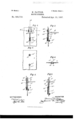
- Figure 1 of the accompanying drawings represents in back elevation one form of automatic match-striker released by the impingement of the head of a match to be lighted against the striking-plate, which is caused to traverse or wipe in a rectilinear direction over the said match-head by the energy of a spring.
- the said view shows the striker set.
- Fig. 2 represents a vertical section of Fig. 1 upon the dotted line x, showing the match just before it is made to impinge against the striker.
- Fig. 3 represents a front elevation of Fig. 1 and Fig. 4 is a cross-section upon the dotted line Fig. 1.
- Fig. 5 represents a likeview as Fig.
- Fig. 6 represents a like section as Figs. 2 and 5, but showing the striker at rest after having been shot or drawn over and taken beyond the match-head, which is thus ignited.
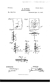
- Fig. 7 represents a front elevation of a modified form of my invention in which the striker is made to travel in a curvilinear course instead of in a rectilinear direction and is actuated or shot by a volute spring.
- Fig. 8 is a back elevation of the same.
- Fig. 9 is a vertical section of Fig. 8, showing the striker in its set position and just before the impingement of the match thereon.
- Fig. 10 is a like section as Fig. 9, but with the match shown impinging against and releasing the striker, which is then momentarily and swiftly drawn over the head; hence the ignition of the match when the parts assume the positions shown in Fig. 11.
- Fig. l2 is a section on the line @c3 x3 of 55 Fig. 8, but with the striker-impelling mechanism in elevation.
- Fig. 13 is a section upon the dotted line m4 of Fig. 8, looking in the direction of the arrow.
- Fig. 14 shows, on an en-larged scale,a section of a part ofthe striker- 6o plate and the hole in the casing of a box,
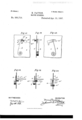
- Fig. 15 is a front elevation of another form of striker in which the strikerplate is impelled in a curvilinear path.
- Fig. 16 is a side elevation of the same, and Fig.
- Fig. 18 is asection upon the dotted line m5, Fig. 17, showing the positions of the parts before the impingement of the match.
- Fig. 19 is a like section, 7o but with the match pushing the hoiding-catch of the striker out of its holding position, so
- Fig. 20 is also alike view as Fig. 18, but showing the striker impelled beyond the range of the match, which is thus struck or ignited.
- a. is a reciprocating striker working between guides a' a2 and impelled by a spring b, located between an end a3 and the guide a2, and when the striker is in its 8o set position a catch a4 engages witha sinking c', formed in a plate or carrier c.
- c2 is a hole in this plate, through which the match d is introduced and impinged against the strikingsurface a5, which may be serrated or roughcned or provided with any other suitable striking-contact, such, for instance, as a knifeedge.
- the striker is set by a knob or other finger-hold a6, whose stem works in a slot or piercing c3 in the carrier-plate. I prefer to 9o lift the striking-surface from the face of the carrier-plate, over which it is reciprocated, so as to prevent injury of the opposed surfaces.
- a is the striker, mounted upon an axis or turn a6 and having the inner end of an impelling-spring b connected to it,
- a4 is a catch engaging with a hole c in the plate c, while c2 is the hole through which the head of the match d is thrust.
- the operation consists in rotating the axis or turn c6 until the catch a4 comes opposite and falls into the hole c, when the striker is retained in its set posi-tion. Then to strike a match thrust the same through the hole c2, when the striker is released by the catch being taken out of the hole and is shot pastand beyond the head of the match by thepentfup force of the propellingesprin g, thereby igniting the same.
- a is the striker, carried by the outer end of any impelling-spring h, whose inner end is connected to a plate o r carrier c, having a slot' a5 within it wherein then-eck of a setting-stud d6 works, and the carrier is' retained. by a catch or collar a4 on the said neck, engaging in the hole c" in the slot a5.
- c2 is the hole through which the' match dis passed.
- the match Afterthe stri-ker is set the match is thrust through the hole c2 and impinged against the striker, whereby the catch a4 is released from the hole c' and the said striker is, bythe impelling force of the spring h, shot overI and past the match-head, which is thus ignited.
- the match after being ignited, if required to light a lamp interiorly, is kept in the inside and passed up to the wick, buty if the light is'reqn-ired exteriorly'then instantly itis struck it is sharply withdrawn.
- the striker passing out of the-range oi thematch it isobvious that a hole near the end of the striker-plate for the match to pass through would give the necessary clearance.
- the striker may be mounted ony a frame and left naked, in which case no hole would be required for the match to-be-thrust Further, it is also ob-v said striker retracted against the tension of its spring, and means for permitting said striker to yield when a match is impinged thereagainst to release the catch and cause the striker to sweep over and ignite the match, substantially as described.
- a match-striker the combination with a carrier having an orifice for the introduce tion of a match, of a reciprocating striker movable in yielding guides ixed on the rear oi' the carrier, a spring for. thrusting said striker over and past said orifice, and a catch for holding said striker retracted against the tension of said' spring, whereby when amatch is introduced into said orifice. and impinged against the striker,v the latter is released and caused to sweep over and ignite the match, substantially as described.
Landscapes
- Engineering & Computer Science (AREA)
- Chemical & Material Sciences (AREA)
- Combustion & Propulsion (AREA)
- Mechanical Engineering (AREA)
- General Engineering & Computer Science (AREA)
- Portable Nailing Machines And Staplers (AREA)
Description
(No Model.) v a sheets-sheen 1.
H. PAYTON.
MATCH STRIKBR.
No.`580,710. l Patented Apr. 13, 1897.
INVENTOR. (8`
ma mums PETERS cn. Pnofuurno.. msnmsron, u. r..
3 vshemm--sheet 2.
(No Model.)
H PAYTON MATCH STRIKER.
Patented Apr. 13, 1897.
w|TNEssEs (No Model.) 3 Sheets-Sheet 3.
1 H. PAYTON.
' MATCH STRIKBB..4 No. 580,710. Patented Apr. 13, 1897.
WITNESSES INVENTOR 'ma cams mzrzRs no, now-mmc.. wAswnamufo. c.
PATENT OFFICE.
HENRY PAYTON, OF BIRMINGHAM, ENGLAND.
MATCH-STRIKER.
SPECIFICATION forming part of Letters Patent No. 580,710, dated April 13, 189'?.
Application filed January 5, 1897. Serial No. 618,063. (No model.) Patented in England August 17, 1896, No. 18,146.
This invention relates to match-strikers for various purposes-such, for instance, as for cycle and other lamps, match-boxes, gas- .burners, and the like, and has for its object an automatic or spring-actuated striker; and
it consists, primarily, of a traversing striker setv by hand andgreleased by the impingement of a match against it.
l Figure 1 of the accompanying drawings represents in back elevation one form of automatic match-striker released by the impingement of the head of a match to be lighted against the striking-plate, which is caused to traverse or wipe in a rectilinear direction over the said match-head by the energy of a spring. The said view shows the striker set. Fig. 2 represents a vertical section of Fig. 1 upon the dotted line x, showing the match just before it is made to impinge against the striker. Fig. 3 represents a front elevation of Fig. 1 and Fig. 4 is a cross-section upon the dotted line Fig. 1. Fig. 5 represents a likeview as Fig. 2, but with the match shown impinging against and forcing back the striker,thus taking the catch which holds the same in its set position out of asinking in its face. Fig. 6 represents a like section as Figs. 2 and 5, but showing the striker at rest after having been shot or drawn over and taken beyond the match-head, which is thus ignited. Fig. 7 represents a front elevation of a modified form of my invention in which the striker is made to travel in a curvilinear course instead of in a rectilinear direction and is actuated or shot by a volute spring. Fig. 8 is a back elevation of the same. Fig. 9 is a vertical section of Fig. 8, showing the striker in its set position and just before the impingement of the match thereon. Fig. 10 is a like section as Fig. 9, but with the match shown impinging against and releasing the striker, which is then momentarily and swiftly drawn over the head; hence the ignition of the match when the parts assume the positions shown in Fig. 11. Fig. l2 is a section on the line @c3 x3 of 55 Fig. 8, but with the striker-impelling mechanism in elevation. Fig. 13 is a section upon the dotted line m4 of Fig. 8, looking in the direction of the arrow. Fig. 14 shows, on an en-larged scale,a section of a part ofthe striker- 6o plate and the hole in the casing of a box,
. lamp, or the like through which the match passes. Fig. 15 is a front elevation of another form of striker in which the strikerplate is impelled in a curvilinear path. Fig. 16 is a side elevation of the same, and Fig.
17 a back elevation thereof. Fig. 18 is asection upon the dotted line m5, Fig. 17, showing the positions of the parts before the impingement of the match. Fig. 19 is a like section, 7o but with the match pushing the hoiding-catch of the striker out of its holding position, so
as to release the same. Fig. 20 is also alike view as Fig. 18, but showing the striker impelled beyond the range of the match, which is thus struck or ignited.
In Figs. 1 to 6, a. is a reciprocating striker working between guides a' a2 and impelled by a spring b, located between an end a3 and the guide a2, and when the striker is in its 8o set position a catch a4 engages witha sinking c', formed in a plate or carrier c. c2 is a hole in this plate, through which the match d is introduced and impinged against the strikingsurface a5, which may be serrated or roughcned or provided with any other suitable striking-contact, such, for instance, as a knifeedge. The striker is set by a knob or other finger-hold a6, whose stem works in a slot or piercing c3 in the carrier-plate. I prefer to 9o lift the striking-surface from the face of the carrier-plate, over which it is reciprocated, so as to prevent injury of the opposed surfaces.
Operation: To set the striker, push the same upward until the catch a4 engages the 95 hole or sinking c', when the parts are retained in their set positions, as shown in Figs. 1 and 2. To strike a match, thrust the head end of the same through the hole c2, when the striker is pushed backward, which is admitted 1 oo i of by the spring-guides a when the catch a4 is removed from the hole c', and the force of the spring now comes into play and shoots the striker by its impelling action, which in its traverse over andv past the head of the match ignites the same, as represented in Fig. 6.
In Figs. 7 to 14, a is the striker, mounted upon an axis or turn a6 and having the inner end of an impelling-spring b connected to it,
while the other end of the spring is attached i to the carrier-plate c and with a connectingspring c4 uniting the striker with the turn. a4 is a catch engaging with a hole c in the plate c, while c2 is the hole through which the head of the match d is thrust. Y
The operation consists in rotating the axis or turn c6 until the catch a4 comes opposite and falls into the hole c, when the striker is retained in its set posi-tion. Then to strike a match thrust the same through the hole c2, when the striker is released by the catch being taken out of the hole and is shot pastand beyond the head of the match by thepentfup force of the propellingesprin g, thereby igniting the same.
In Figs. l5 to 20, a is the striker, carried by the outer end of any impelling-spring h, whose inner end is connected to a plate o r carrier c, having a slot' a5 within it wherein then-eck of a setting-stud d6 works, and the carrier is' retained. by a catch or collar a4 on the said neck, engaging in the hole c" in the slot a5. c2 is the hole through which the' match dis passed. Afterthe stri-ker is set the match is thrust through the hole c2 and impinged against the striker, whereby the catch a4 is released from the hole c' and the said striker is, bythe impelling force of the spring h, shot overI and past the match-head, which is thus ignited. The match, after being ignited, if required to light a lamp interiorly, is kept in the inside and passed up to the wick, buty if the light is'reqn-ired exteriorly'then instantly itis struck it is sharply withdrawn.
Instead of the tail end oi, the striker passing out of the-range oi thematch it isobvious that a hole near the end of the striker-plate for the match to pass through would give the necessary clearance. vious that the striker may be mounted ony a frame and left naked, in which case no hole would be required for the match to-be-thrust Further, it is also ob-v said striker retracted against the tension of its spring, and means for permitting said striker to yield when a match is impinged thereagainst to release the catch and cause the striker to sweep over and ignite the match, substantially as described.
3. In amatch-striker, the combination with a carrier having an oriice for the introduction ofv a match,a,striker arranged to move A past said aperture, a spring for actuating said striker, a catch for holding said striker retracted against the tension of said spring, and
means for maintaining said catch in its operative position to hold the striker in its retracted position but permitting the catch to be released by the impingement of a match against the striker to cause the striker to sweep over and ignite the match, substantially as described.
4. Inamatch-striker, the combination with a carrier, of a spring-impelled striker movably attached thereto, and a catch for holding said striker in its retracted position said carrier havin g an orifice disposed over said striker for the introduction ofy a match to release the striker and cause it to sweep over and ignite the match, substantially as described.
5. In a match-striker, the combination with a carrier having an orifice for the introduce tion of a match, of a reciprocating striker movable in yielding guides ixed on the rear oi' the carrier, a spring for. thrusting said striker over and past said orifice, and a catch for holding said striker retracted against the tension of said' spring, whereby when amatch is introduced into said orifice. and impinged against the striker,v the latter is released and caused to sweep over and ignite the match, substantially as described.
6. In a match-striker, the combination with the carrier c' having an orifice c2'and slotted as at c3, yielding` guides a', a striker a movably arranged in said guides and provided with a. knob a6' projecting through said slot, a spring for thrusting said striker over and past said orifice, and a catch a4 arranged to v engage a recessl c" in the carrier and hold the stri-ker retracted against the tension of the spring, whereby when a match is introduced into said orice and impinged against the striker, the latter is released and sweeps over and ignites. the match, substantially as described.
In testimony whereof I have hereunto set my hand in presence oi two subscribing witnesses.
HENRY PAYTON. Witnesses:
HENRY SKERRETT, ARTHUR T. .SADLER IOO IIO
Publications (1)
| Publication Number | Publication Date |
|---|---|
| US580710A true US580710A (en) | 1897-04-13 |
Family
ID=2649388
Family Applications (1)
| Application Number | Title | Priority Date | Filing Date |
|---|---|---|---|
| US580710D Expired - Lifetime US580710A (en) | payton |
Country Status (1)
| Country | Link |
|---|---|
| US (1) | US580710A (en) |
-
0
- US US580710D patent/US580710A/en not_active Expired - Lifetime
Similar Documents
| Publication | Publication Date | Title |
|---|---|---|
| US1259463A (en) | Air-gun. | |
| US2037313A (en) | Gun | |
| US1803366A (en) | Signal rocket | |
| US1860611A (en) | Toy rapid-fire gun | |
| US929311A (en) | Repeating cap-pistol. | |
| US644969A (en) | Automatic gun. | |
| US2290995A (en) | Carrier construction in toy pistols | |
| US1834029A (en) | Combined cigarette dispensing apparatus and lighter | |
| US1883028A (en) | Gun | |
| US847011A (en) | Firearm. | |
| US1666579A (en) | Scaring pistol | |
| US592882A (en) | Automatic fire-lighter | |
| US1554827A (en) | Incendiary projectile | |
| US769919A (en) | Toy gun. | |
| US191794A (en) | Improvement in cigar-lighters | |
| US968691A (en) | Revolver. | |
| US1965247A (en) | Toy pistol | |
| US876683A (en) | Repeating torpedo-cane. | |
| US185789A (en) | Improvement in toy blow-guns | |
| US698406A (en) | Match-safe. | |
| US1504137A (en) | Sporting gun with superposed barrels | |
| US896669A (en) | Breech-operating mechanism for ordnance. | |
| US1090728A (en) | Lantern. | |
| US1335487A (en) | Automatic gun | |
| US627232A (en) | Fusee thrower and guide |