US5697146A - Apparatus for crimping terminal to electrical wire - Google Patents
Apparatus for crimping terminal to electrical wire Download PDFInfo
- Publication number
- US5697146A US5697146A US08/576,083 US57608395A US5697146A US 5697146 A US5697146 A US 5697146A US 57608395 A US57608395 A US 57608395A US 5697146 A US5697146 A US 5697146A
- Authority
- US
- United States
- Prior art keywords
- crimper
- motor
- servo
- circular plate
- crimping
- Prior art date
- Legal status (The legal status is an assumption and is not a legal conclusion. Google has not performed a legal analysis and makes no representation as to the accuracy of the status listed.)
- Expired - Lifetime
Links
Images


Classifications
-
- B—PERFORMING OPERATIONS; TRANSPORTING
- B30—PRESSES
- B30B—PRESSES IN GENERAL
- B30B1/00—Presses, using a press ram, characterised by the features of the drive therefor, pressure being transmitted directly, or through simple thrust or tension members only, to the press ram or platen
- B30B1/26—Presses, using a press ram, characterised by the features of the drive therefor, pressure being transmitted directly, or through simple thrust or tension members only, to the press ram or platen by cams, eccentrics, or cranks
- B30B1/266—Drive systems for the cam, eccentric or crank axis
-
- H—ELECTRICITY
- H01—ELECTRIC ELEMENTS
- H01R—ELECTRICALLY-CONDUCTIVE CONNECTIONS; STRUCTURAL ASSOCIATIONS OF A PLURALITY OF MUTUALLY-INSULATED ELECTRICAL CONNECTING ELEMENTS; COUPLING DEVICES; CURRENT COLLECTORS
- H01R43/00—Apparatus or processes specially adapted for manufacturing, assembling, maintaining, or repairing of line connectors or current collectors or for joining electric conductors
- H01R43/04—Apparatus or processes specially adapted for manufacturing, assembling, maintaining, or repairing of line connectors or current collectors or for joining electric conductors for forming connections by deformation, e.g. crimping tool
- H01R43/048—Crimping apparatus or processes
- H01R43/0488—Crimping apparatus or processes with crimp height adjusting means
-
- Y—GENERAL TAGGING OF NEW TECHNOLOGICAL DEVELOPMENTS; GENERAL TAGGING OF CROSS-SECTIONAL TECHNOLOGIES SPANNING OVER SEVERAL SECTIONS OF THE IPC; TECHNICAL SUBJECTS COVERED BY FORMER USPC CROSS-REFERENCE ART COLLECTIONS [XRACs] AND DIGESTS
- Y10—TECHNICAL SUBJECTS COVERED BY FORMER USPC
- Y10S—TECHNICAL SUBJECTS COVERED BY FORMER USPC CROSS-REFERENCE ART COLLECTIONS [XRACs] AND DIGESTS
- Y10S72/00—Metal deforming
- Y10S72/712—Electrical terminal crimper
-
- Y—GENERAL TAGGING OF NEW TECHNOLOGICAL DEVELOPMENTS; GENERAL TAGGING OF CROSS-SECTIONAL TECHNOLOGIES SPANNING OVER SEVERAL SECTIONS OF THE IPC; TECHNICAL SUBJECTS COVERED BY FORMER USPC CROSS-REFERENCE ART COLLECTIONS [XRACs] AND DIGESTS
- Y10—TECHNICAL SUBJECTS COVERED BY FORMER USPC
- Y10T—TECHNICAL SUBJECTS COVERED BY FORMER US CLASSIFICATION
- Y10T29/00—Metal working
- Y10T29/49—Method of mechanical manufacture
- Y10T29/49002—Electrical device making
- Y10T29/49117—Conductor or circuit manufacturing
- Y10T29/49174—Assembling terminal to elongated conductor
- Y10T29/49181—Assembling terminal to elongated conductor by deforming
- Y10T29/49185—Assembling terminal to elongated conductor by deforming of terminal
-
- Y—GENERAL TAGGING OF NEW TECHNOLOGICAL DEVELOPMENTS; GENERAL TAGGING OF CROSS-SECTIONAL TECHNOLOGIES SPANNING OVER SEVERAL SECTIONS OF THE IPC; TECHNICAL SUBJECTS COVERED BY FORMER USPC CROSS-REFERENCE ART COLLECTIONS [XRACs] AND DIGESTS
- Y10—TECHNICAL SUBJECTS COVERED BY FORMER USPC
- Y10T—TECHNICAL SUBJECTS COVERED BY FORMER US CLASSIFICATION
- Y10T29/00—Metal working
- Y10T29/49—Method of mechanical manufacture
- Y10T29/49758—During simulated operation or operating conditions
- Y10T29/4976—Temperature
-
- Y—GENERAL TAGGING OF NEW TECHNOLOGICAL DEVELOPMENTS; GENERAL TAGGING OF CROSS-SECTIONAL TECHNOLOGIES SPANNING OVER SEVERAL SECTIONS OF THE IPC; TECHNICAL SUBJECTS COVERED BY FORMER USPC CROSS-REFERENCE ART COLLECTIONS [XRACs] AND DIGESTS
- Y10—TECHNICAL SUBJECTS COVERED BY FORMER USPC
- Y10T—TECHNICAL SUBJECTS COVERED BY FORMER US CLASSIFICATION
- Y10T29/00—Metal working
- Y10T29/51—Plural diverse manufacturing apparatus including means for metal shaping or assembling
- Y10T29/5193—Electrical connector or terminal
-
- Y—GENERAL TAGGING OF NEW TECHNOLOGICAL DEVELOPMENTS; GENERAL TAGGING OF CROSS-SECTIONAL TECHNOLOGIES SPANNING OVER SEVERAL SECTIONS OF THE IPC; TECHNICAL SUBJECTS COVERED BY FORMER USPC CROSS-REFERENCE ART COLLECTIONS [XRACs] AND DIGESTS
- Y10—TECHNICAL SUBJECTS COVERED BY FORMER USPC
- Y10T—TECHNICAL SUBJECTS COVERED BY FORMER US CLASSIFICATION
- Y10T29/00—Metal working
- Y10T29/53—Means to assemble or disassemble
- Y10T29/5313—Means to assemble electrical device
- Y10T29/532—Conductor
- Y10T29/53209—Terminal or connector
- Y10T29/53213—Assembled to wire-type conductor
- Y10T29/53235—Means to fasten by deformation
Definitions
- This invention relates to an apparatus for crimping a terminal to an electrical wire, which manufactures terminal-equipped wires for configuring a wire harness, or the like.
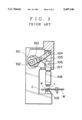
- a terminal crimping apparatus provided with a flywheel, as shown in FIG. 9, as one of the instant type for performing the crimping method.
- the flywheel 101 driven by a motor (not shown), rotates at a constant speed in the direction of an arrow head, and a crank arm 103 pivotably attached to an off-center pin 102 pivots around a pivot axis 104.
- the crank arm 103 vertically reciprocates a ram 107 pivotably attached by an axial pin 106 to the crank arm 103 by way of a connection arm 105, which vertically reciprocates a crimper 108 integrally connected to the ram 107.
- the crimper 108 and a cooperative anvil 109 compress and crimp a stripped wire end w of a wire W to a barrel c of a terminal C.
- the above-mentioned flywheel-type crimping apparatus is suitable for mass production because the crimper 108 vertically reciprocates with higher speeds.
- the crimper 108 passes instantaneously its bottom dead point (it is not stopped at the bottom dead point), its crimping operation is instantaneous, resulting in the disadvantage of an insufficient tensile strength in the crimped terminals.
- FIG. 11 shows the relation between time and position of the crimper 108 and explains that a crimping, contacting period t 0 of the crimper 108 and the terminal C is only an instant.
- the crimping apparatus has the disadvantages that the size of the flywheel 101 determines the press depth (crimp height), that the motor running cost is large, and that it is difficult to detect an abnormal state during crimping operation. Additionally, a crimp height is not easily adjusted because only a lowest position of the crimper is selected so that the anvil height should be modified in a crimp height adjustment.
- a crimping apparatus as shown in FIG. 10, having a crimper 108' vertically moved by the rotation of a lead screw 110.
- Designated 111 is a servo-motor, 112 a primary wheel, 113 a secondary wheel, and 114 a timing belt.
- the above-mentioned lead-screw-type crimping apparatus also has the disadvantages that a large-scale apparatus is required to obtain a larger crimping load, that its operation speed is normally lower to result in lower productivity, and that many sensors are required to determine whether a terminal is correctly crimped, or otherwise a manual determination is required. Additionally, the screw mechanism is not suitable to a minute adjustment of crimp height.
- an object of the invention is to provide an apparatus for crimping electrical terminals that obtain a sufficient crimping strength while keeping a higher speed in terminal crimping operation and further that is compact in size.
- Another object of the present invention is to provide a terminal crimping apparatus having a mechanism capable of easily adjusting crimp heights.
- an apparatus for crimping a terminal to an electrical wire includes a crimper vertically reciprocating to crimp electric terminals to conductors of a stripped wire; an anvil opposing the crimper; and a means for vertically reciprocating the crimper, wherein such means has a piston-crank mechanism to vertically reciprocate a ram attached to the crimper and a servo-motor connected to a circular plate in the piston-crank mechanism by way of a reduction gear.
- the circular plate in the piston-crank mechanism pivots within the angular range of 0 to 180 degrees by the rotation of the servo-motor.
- the forwardly and reversely rotating servo-motor can reciprocate the crimper at a higher speed by way of the piston-crank mechanism, which enables a higher terminal-crimping operation to provide higher productivity.
- the crimping apparatus is smaller and easier in the adjustment of crimp height by controlling the number of rotations in the servo-motor, that is, by changing the pivoting range of the circular plate.
- the servo-motor can halt when the crimper is in a crimping position so that terminal barrels are restricted from a spring-back to obtain reliable products with high crimping strength.
- controlling descending speeds of the crimper around the crimping position eliminates impulsive noises that are brought about in conventional flywheel-type crimping apparatuses.
- FIG. 1 is the front view showing an embodiment of a terminal crimping apparatus according to this invention
- FIG. 2 is a side view of the terminal crimping apparatus in FIG. 1;
- FIG. 3 is a functional block diagram showing a control system of the terminal crimping apparatus in FIG. 1;
- FIG. 4 is a flow chart showing a first part of the operation of the control system of FIG. 3;
- FIG. 5 is a flow chart showing a remaining part of the operation of the control system of FIG. 3;
- FIGS. 6A, 6B and 6C are illustrations respectively showing various operation steps of the terminal crimping apparatus in FIG. 1;
- FIG. 7A is a graph showing the relation between time and the vertically reciprocating speed of a crimper in a crimping operation cycle controlled by the control system in FIG. 3, and FIG. 7B is a graph showing the relation between time and the motor current of the same;
- FIG. 8 is a graph explaining a method for determining whether crimping is normal based on the motor driving currents
- FIG. 8B is a graph for explaining a method for determining whether crimping is normal based on the detected crimper heights.
- FIG. 9 is an illustration explaining a terminal crimping apparatus of the prior art.
- FIG. 10 is an illustration explaining another terminal crimping apparatus of the prior art.
- FIG. 11 is a typical graph showing the relation between time and the position of a crimper in a terminal crimping operation regarding a terminal crimping apparatus of the prior art.
- FIGS. 1 and 2 designated as 1 is a casing for a terminal crimping apparatus A according to the present invention, which has a base plate 2 and side plates 3, 3 positioned on each side of the base plate 2.
- the reduction gear 5 has an output axis 6 that axially connects to a circular plate 7 with an off-center pin 8.
- the off-center pin 8 is slidably axially connected to an upper end portion of a crank arm 9, a lower end portion of which being pivotably axially connected to a ram 11 by way of an axial pin 10.
- the ram 11 is disposed to slide upward and downward in ram guides 12, 12 provided on inner surfaces of both the side plates 3, 3.
- the circular plate 7, the crank arm 9, the ram 11 and the ram guides 12, 12 compose a piston-crank mechanism B.
- the engaging recess or slot 13 detachably engages with an enlarged head portion 16 of a crimper holder 15 holding a crimper 14.
- an anvil 17 is fixed on the base plate 2 in opposition to the crimper 14.
- Designated 18 is a guide plate for guiding the crimper holder 15, the guide plate 18 being fixed to an inner surface of the side plate 3 by way of a bracket (not shown).
- the servo-motor 4 can rotate forwardly and reversely, which vertically reciprocates the crimper 14 by way of the ram 11 pivotably attached to the crank arm 9 by the piston-crank mechanism B. Further, the servo-motor 4 connects to a driver control device 34 that controls the servo-motor operation.
- the driver control device 34 connects to a reference data input unit 22 that inputs reference data, such as terminal specifications (or terminal sizes), relative wire sizes, crimp heights (lowest descended positions of the crimper), and loads (electric currents) to be applied to the servo-motor 4.
- a rotary encoder 33 that detects positions of the crimper 14 based on the extent of rotation of the servo-motor and feeds the information back to the driver control device 34 that reads out the above-mentioned load current.
- Designated 32 is a height sensor that senses the height of the crimper 14 just when a terminal is crimped. The sensor 32 is operative to output the sensed height to the driver control device 34 that determines whether the terminal crimping operation is correct. Furthermore, designated 31 is a temperature sensor for sensing the temperature of a coil in the servo-motor 4.
- FIG. 3 is a functional block diagram of the driver control device 34 that controls the servo-motor 4 in operation.
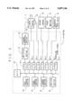
- the driver control device 34 is integrated as a control circuit, such as a central processing unit, and includes a data storage section 23, a speed control section 24, a current control section 25, a decision section 28, an amplifying section 27, a current detecting section 28, interfaces I/O 29-1 to 29-8, and a microprocessor unit(MPU) 30.
- MPU microprocessor unit
- FIGS. 6A, 6B and 6C are diagrams explaining the operation of the terminal crimping apparatus.
- FIG. 7A is a graph showing the relation between time and the vertically reciprocating speed of the crimper 14 in the operation.
- FIG. 7B is a graph showing the relation between time and the current of the servo-motor in the same operation.
- the points designated as T1, T2, and T3 in FIGS. 7B correspond to the respective conditions of the apparatus shown in FIG. 6A, 6B, and 6C.
- FIG. 6A shows an initial step in the terminal crimping operation, in which the off-center pin 8 on the circular plate 7 is at the highest position, that is, the crimper 14 is at the top dead point. At that time, as shown in FIG. 7A, the descending speed of the crimper 14 is zero and the load current in the servo-motor 4 is also zero.
- FIG. 6B shows an initial crimping step, in which the circular plate 7 rotates in the arrow head direction; the off-center pin 8 moves downward; and the crimper 14 has descended at a higher speed before abutting the barrel c of the terminal C. However, the descending speed of the crimper 14 is decelerated and the load current for the servo-motor is reduced prior to the abutment.
- FIG. 6C shows a stopping state in which the crimper 14 has stopped at its crimping position, after the circular plate 7 rotates in the arrow head direction so that the off-center pin 8 reaches near its bottom dead point and the crimper 14 and anvil 17 carry out a crimping operation.
- the crimper 14 operates to press the barrel c of the terminal C so as to continue to oppose against spring-back of the barrel c. Thereby, the load current reaches to a peak of a maximum rate.
- the press in the stopping state eliminates the spring-back of the barrel c to obtain a high crimping strength.
- the servo-motor 4 reversely rotates, that is, the circular plate 7 rotates in the reverse direction to the arrow head in FIG. 6C so that the crimper ascends to return to the original state of FIG. 6A.
- the data storage section 23 stores data for operating the crimping apparatus A and data for determining whether terminals are correctly crimped from the reference data input unit 22 by way of I/O 29-7.
- the stored data for operating the crimping apparatus A are accelerated speeds of the servo-motor after the servo motor begins to normally rotate at T1, a position of the crimper 14 when the crimper descending speed reaches a uniform rate during the descending of the crimper 14 activated by the motor rotation, a position of the crimper 14 and decelerated speeds of the crimper 14 when the crimper decelerates from the uniform rate at T2, a crimping start position of the crimper 14 at T3, a given time t and a driving current to drive the servo-motor during the given time, accelerated speeds of the servo-motor when the servo-motor begins to reversely rotate to ascend the crimper 14 after a terminal is crimped at T4, a position of the crimper 14 when the crimper ascending speed reaches to another uniform rate, a position of the crimper 14 when the crimper decelerates from another uniform rate, and
- data of the positions of the crimper 14 are stored as corresponding to output values from the rotary encoder 33 attached to the servo-motor 4.
- position data of the crimper 14 are stored to correspond to output values of the rotary encoder 33, that is, as corresponding to pivoting angles of the circular plate 7.
- the data for determining whether terminals are correctly crimped include, as described later in detail, currents IU and IL shown in FIG. 7B or the like.
- I denotes a detected current when a certain terminal is normally crimped to a corresponding size wire
- IU and IL denote an upper limit and a lower limit of the detected current, respectively, IU and IL being determined based on a preliminary test result.
- the graph of FIG. 17 shows a normal crimping in which I is between IL and IU.
- FIGS. 4 and 5 show operational flow charts of the driver 34.
- step S1 the speed control section 24 decides whether a starting signal to begin a crimping operation is inputted by way of I/O 29-8, and if the decision is NO, the operation does not start until the decision becomes YES.
- step S2 the speed control section 24 reads out a normally accelerated rotating speed of the servo-motor 4 from the data storage section 23, and outputs a signal to the amplifying section 27 by way of I/O 29-1 so that the amplifying section 27 supplies a current to the servo-motor 4 in such way that the servo-motor 4 rotates at the read out accelerated speed.
- the values outputted from the rotary encoder 33 by way of I/O 29-3 are differentiated to obtain rotation speeds of the motor and further the rotation speeds are differentiated to determine rotation accelerations of the motor.
- step S3 The speed control section 24 determines whether a value outputted from the rotary encoder 33 by way of I/O 29-3 becomes equal to the value that is stored in the data storage section 23 and corresponds to a position from which a uniform rotation speed begins. If the decision is NO, step S2 continues to accelerate the motor, while if the decision is YES, a following step S4 makes the motor rotate at a uniform speed.
- step S5 in the speed control section 24 detects the arrival at the deceleration starting position of the motor
- step S8 decelerates the rotation of the motor.
- the next step S7 decides whether the crimper has reached the terminal crimping position, and if the decision is YES, the step S7 outputs a corresponding signal to the current control section 25.
- step S8 reads out a current I stored in the data storage section 23 and which is required by the servo-motor 4 just in a crimping stage.
- step S9 corrects the current I based on a temperature outputted from the temperature sensor 31 by way of I/O 29-4 so that the motor torque becomes equal to the reference value. Further, the following step S10 outputs the current I by way of I/O 29-1.
- step S11 records the decision reference data in a memory (not shown).
- the decision reference data will be discussed later in detail.
- step S12 determines whether the servo-motor 4 has received the current I during the time t, and if the decision is NO, the steps S10 and S11 are executed again.
- step S13 reversely rotates the servo-motor 4 with a predetermined acceleration, and, if step S14 decides that the motor rotation has reached a uniform speed, the following step S15 controls the motor such that it rotate at the uniform speed.
- step S17 decelerates the motor and step S18 stops the motor rotation based on the arrival at a stopping position.
- step S19 determines whether the latest crimping operation has been normal based on the data recorded in step S11. Then, the following step S20 displays the results in a crimp monitor 21 and also outputs a warning signal in the case of an abnormal crimping operation.
- step S11 For determining whether the crimping operation is normal, as shown in FIG, 8A, step S11 records current values (driving current), which are detected in the current detecting section 28 and supplied to the servo-motor 4 at a constant time interval.
- FIG. 8A shows the driving current supplied to the motor 4 at the crimping operation in FIG. 7B.
- the current control section 25 controls in such way that standard currents, the values of which are stored in the data storage section, are supplied to the motor.
- a uniform current is supplied to the motor, while the motor driving current changes when the motor begins to rotate to result in a modified control balance.
- the supplied current becomes smaller or larger than the standard current in the normal crimping operation. Accordingly, in the present invention, whether the crimping is normal is decided based on thus changed current supplied to the motor.
- FIG. 8B shows an output from the height sensor 32 when a terminal is crimped.
- the resulting crimp height outputted at each time interval becomes lower than, or is different from, the normal crimp height. Therefore, in the present invention, whether the crimping is normal is determined based on the thus-changed crimp height.
- a first decision method includes the steps of: reading out a maximum value among driving currents recorded in the step S11 in a predetermined period; determining whether the maximum value is within the standard values stored in the data storage section 23; and determining whether the crimping has been normally carried out based upon whether the maximum value is within the range of the standard values.
- a second decision method includes the steps of: recording reference currents during a predetermined period in the data storage section 23; obtaining the differences between the time series current values recorded in the step S11 and the reference currents; and deciding whether the crimping has been normally carried out based upon whether the difference is within a predetermined range.
- a third decision method includes the steps of: obtaining the sum of the current values recorded in the step S11 at a constant interval during a predetermined period; and deciding whether the crimping has been normally carried out based upon whether the sum is within a predetermined range.
- a fourth decision method includes, as shown in FIG. 8B, the steps of: recording heights outputted from the height sensor 32 by way of I/O 29-5 in data recording of the step S11; obtaining a minimum value among the recorded data; and deciding whether the crimping has been normally carried out based upon whether the minimum value is within a predetermined range.
- a fifth decision method includes the steps of: recording heights outputted from the height sensor 32; obtaining a minimum value among the recorded data; and comparing the time series heights with the corresponding reference values, and deciding whether the crimping has been normally carried out based upon whether the differences are within a predetermined range.
- the decision may be carried out based on both the driving current and the crimper height.
- the off-center pin 8 pivots within the range of 0 to 180 degrees and a crimp height (the lowest position of the crimper 14) is adjusted by the pivoting range of the off-center pin 8. That is, random adjustments of crimp height are capable by controlling the number of rotatione in the servo-motor 4 by the driver control device 34.
- monitoring load currents I in the servo-motor 4 or monitoring the height of the crimper 14 can determine whether the crimping operation is normal or not, that is, whether a product is non-defective during crimping operation. Moreover, a stopping period t is provided in crimping operation so that the terminal barrel is prevented from its spring-back, resulting in reliable stable crimping and reliable products.
- the normally and reversely rotating electrical servo-motor 4 is adopted to vertically reciprocate the crimper 14, the electrical servo-motor may be replaced by a hydrostatic servo-motor.
Landscapes
- Engineering & Computer Science (AREA)
- Manufacturing & Machinery (AREA)
- Mechanical Engineering (AREA)
- Manufacturing Of Electrical Connectors (AREA)
- Control Of Presses (AREA)
Abstract
An apparatus for crimping a terminal includes a crimper vertically reciprocating to crimp electric terminals to conductors of a striped wire, and anvil opposing the crimper, and an operating mechanism for vertically reciprocating the crimper. The operating mechanism has a piston-crank apparatus to vertically reciprocate a ram attached to the crimper and a servo-motor connected to a circular plate in the piston-crank mechanism by way of a reduction gear. The operating mechanism also has a control device that stops the servo-motor for a given time period when the crimper is positioned at its lowest position to prevent spring-back of the crimper material.
Description
1. Field of the Invention
This invention relates to an apparatus for crimping a terminal to an electrical wire, which manufactures terminal-equipped wires for configuring a wire harness, or the like.
2. Description of the Prior Art
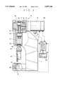
There has been used for a long time a terminal crimping apparatus provided with a flywheel, as shown in FIG. 9, as one of the instant type for performing the crimping method. In the apparatus, the flywheel 101, driven by a motor (not shown), rotates at a constant speed in the direction of an arrow head, and a crank arm 103 pivotably attached to an off-center pin 102 pivots around a pivot axis 104. Further, the crank arm 103 vertically reciprocates a ram 107 pivotably attached by an axial pin 106 to the crank arm 103 by way of a connection arm 105, which vertically reciprocates a crimper 108 integrally connected to the ram 107. Thereby, the crimper 108 and a cooperative anvil 109 compress and crimp a stripped wire end w of a wire W to a barrel c of a terminal C.
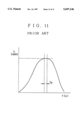
The above-mentioned flywheel-type crimping apparatus is suitable for mass production because the crimper 108 vertically reciprocates with higher speeds. However, as the crimper 108 passes instantaneously its bottom dead point (it is not stopped at the bottom dead point), its crimping operation is instantaneous, resulting in the disadvantage of an insufficient tensile strength in the crimped terminals. FIG. 11 shows the relation between time and position of the crimper 108 and explains that a crimping, contacting period t0 of the crimper 108 and the terminal C is only an instant. Moreover, the crimping apparatus has the disadvantages that the size of the flywheel 101 determines the press depth (crimp height), that the motor running cost is large, and that it is difficult to detect an abnormal state during crimping operation. Additionally, a crimp height is not easily adjusted because only a lowest position of the crimper is selected so that the anvil height should be modified in a crimp height adjustment.
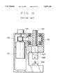
Besides, in Japanese Utility Model Publication No. Hei 6-25911, there is provided a crimping apparatus, as shown in FIG. 10, having a crimper 108' vertically moved by the rotation of a lead screw 110. Designated 111 is a servo-motor, 112 a primary wheel, 113 a secondary wheel, and 114 a timing belt.
Nevertheless, the above-mentioned lead-screw-type crimping apparatus also has the disadvantages that a large-scale apparatus is required to obtain a larger crimping load, that its operation speed is normally lower to result in lower productivity, and that many sensors are required to determine whether a terminal is correctly crimped, or otherwise a manual determination is required. Additionally, the screw mechanism is not suitable to a minute adjustment of crimp height.
In view of the aforementioned drawbacks, an object of the invention is to provide an apparatus for crimping electrical terminals that obtain a sufficient crimping strength while keeping a higher speed in terminal crimping operation and further that is compact in size.
Another object of the present invention is to provide a terminal crimping apparatus having a mechanism capable of easily adjusting crimp heights.
To achieve the above-mentioned object, according to this invention, an apparatus for crimping a terminal to an electrical wire includes a crimper vertically reciprocating to crimp electric terminals to conductors of a stripped wire; an anvil opposing the crimper; and a means for vertically reciprocating the crimper, wherein such means has a piston-crank mechanism to vertically reciprocate a ram attached to the crimper and a servo-motor connected to a circular plate in the piston-crank mechanism by way of a reduction gear.
Preferably, the circular plate in the piston-crank mechanism pivots within the angular range of 0 to 180 degrees by the rotation of the servo-motor.
Referring to operation of the present invention, the forwardly and reversely rotating servo-motor can reciprocate the crimper at a higher speed by way of the piston-crank mechanism, which enables a higher terminal-crimping operation to provide higher productivity.
Further, differing from a conventional flywheel-type or lead-screw-type crimping apparatus, the crimping apparatus according to the present invention is smaller and easier in the adjustment of crimp height by controlling the number of rotations in the servo-motor, that is, by changing the pivoting range of the circular plate.
Moreover, the servo-motor can halt when the crimper is in a crimping position so that terminal barrels are restricted from a spring-back to obtain reliable products with high crimping strength. Besides, controlling descending speeds of the crimper around the crimping position eliminates impulsive noises that are brought about in conventional flywheel-type crimping apparatuses.
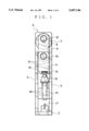
FIG. 1 is the front view showing an embodiment of a terminal crimping apparatus according to this invention;
FIG. 2 is a side view of the terminal crimping apparatus in FIG. 1;
FIG. 3 is a functional block diagram showing a control system of the terminal crimping apparatus in FIG. 1;
FIG. 4 is a flow chart showing a first part of the operation of the control system of FIG. 3;
FIG. 5 is a flow chart showing a remaining part of the operation of the control system of FIG. 3;
FIGS. 6A, 6B and 6C are illustrations respectively showing various operation steps of the terminal crimping apparatus in FIG. 1;
FIG. 7A is a graph showing the relation between time and the vertically reciprocating speed of a crimper in a crimping operation cycle controlled by the control system in FIG. 3, and FIG. 7B is a graph showing the relation between time and the motor current of the same;
FIG. 8 is a graph explaining a method for determining whether crimping is normal based on the motor driving currents, and FIG. 8B is a graph for explaining a method for determining whether crimping is normal based on the detected crimper heights.
FIG. 9 is an illustration explaining a terminal crimping apparatus of the prior art;
FIG. 10 is an illustration explaining another terminal crimping apparatus of the prior art; and
FIG. 11 is a typical graph showing the relation between time and the position of a crimper in a terminal crimping operation regarding a terminal crimping apparatus of the prior art.
In FIGS. 1 and 2, designated as 1 is a casing for a terminal crimping apparatus A according to the present invention, which has a base plate 2 and side plates 3, 3 positioned on each side of the base plate 2. In the rear of, and above both, the side plates 3, 3, there is provided and fixed an electrical servo-motor 4 with a reduction gear 5. The reduction gear 5 has an output axis 6 that axially connects to a circular plate 7 with an off-center pin 8. The off-center pin 8 is slidably axially connected to an upper end portion of a crank arm 9, a lower end portion of which being pivotably axially connected to a ram 11 by way of an axial pin 10. The ram 11 is disposed to slide upward and downward in ram guides 12, 12 provided on inner surfaces of both the side plates 3, 3. The circular plate 7, the crank arm 9, the ram 11 and the ram guides 12, 12 compose a piston-crank mechanism B.
The ram 11, at a lower end thereof, has an engaging recess or slot 13. The engaging recess or slot 13 detachably engages with an enlarged head portion 16 of a crimper holder 15 holding a crimper 14. Just below the crimper 14, an anvil 17 is fixed on the base plate 2 in opposition to the crimper 14. Designated 18 is a guide plate for guiding the crimper holder 15, the guide plate 18 being fixed to an inner surface of the side plate 3 by way of a bracket (not shown).
The servo-motor 4 can rotate forwardly and reversely, which vertically reciprocates the crimper 14 by way of the ram 11 pivotably attached to the crank arm 9 by the piston-crank mechanism B. Further, the servo-motor 4 connects to a driver control device 34 that controls the servo-motor operation. The driver control device 34 connects to a reference data input unit 22 that inputs reference data, such as terminal specifications (or terminal sizes), relative wire sizes, crimp heights (lowest descended positions of the crimper), and loads (electric currents) to be applied to the servo-motor 4. Further, on an output axis (not shown) of the servo-motor 4 there is attached a rotary encoder 33 that detects positions of the crimper 14 based on the extent of rotation of the servo-motor and feeds the information back to the driver control device 34 that reads out the above-mentioned load current.
Designated 32 is a height sensor that senses the height of the crimper 14 just when a terminal is crimped. The sensor 32 is operative to output the sensed height to the driver control device 34 that determines whether the terminal crimping operation is correct. Furthermore, designated 31 is a temperature sensor for sensing the temperature of a coil in the servo-motor 4.
FIG. 3 is a functional block diagram of the driver control device 34 that controls the servo-motor 4 in operation. As shown in the figure, the driver control device 34 is integrated as a control circuit, such as a central processing unit, and includes a data storage section 23, a speed control section 24, a current control section 25, a decision section 28, an amplifying section 27, a current detecting section 28, interfaces I/O 29-1 to 29-8, and a microprocessor unit(MPU) 30.
Next, before explaining detailed operation of the embodiment of the present invention, the basic operation of the embodiment is discussed referring to FIGS. 6 and 7.
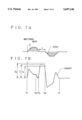
FIGS. 6A, 6B and 6C are diagrams explaining the operation of the terminal crimping apparatus. FIG. 7A is a graph showing the relation between time and the vertically reciprocating speed of the crimper 14 in the operation. Further, FIG. 7B is a graph showing the relation between time and the current of the servo-motor in the same operation. Besides, the points designated as T1, T2, and T3 in FIGS. 7B correspond to the respective conditions of the apparatus shown in FIG. 6A, 6B, and 6C.
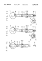
FIG. 6A shows an initial step in the terminal crimping operation, in which the off-center pin 8 on the circular plate 7 is at the highest position, that is, the crimper 14 is at the top dead point. At that time, as shown in FIG. 7A, the descending speed of the crimper 14 is zero and the load current in the servo-motor 4 is also zero.
FIG. 6B shows an initial crimping step, in which the circular plate 7 rotates in the arrow head direction; the off-center pin 8 moves downward; and the crimper 14 has descended at a higher speed before abutting the barrel c of the terminal C. However, the descending speed of the crimper 14 is decelerated and the load current for the servo-motor is reduced prior to the abutment.
FIG. 6C shows a stopping state in which the crimper 14 has stopped at its crimping position, after the circular plate 7 rotates in the arrow head direction so that the off-center pin 8 reaches near its bottom dead point and the crimper 14 and anvil 17 carry out a crimping operation. At that time, as the crimper 14 has been stopping during a stopping period t, the crimper 14 operates to press the barrel c of the terminal C so as to continue to oppose against spring-back of the barrel c. Thereby, the load current reaches to a peak of a maximum rate. The press in the stopping state eliminates the spring-back of the barrel c to obtain a high crimping strength.
After the terminal is crimped, the servo-motor 4 reversely rotates, that is, the circular plate 7 rotates in the reverse direction to the arrow head in FIG. 6C so that the crimper ascends to return to the original state of FIG. 6A.
In FIG. 7A, at the crimping start position, that is, at T2, the descending speed of the crimper 14 is considerably smaller than the speed in which the crimper 14 descends from the top position to the crimping start position. Therefore, there are no impulsive noises generated in the conventional flywheel-type crimping apparatus, which reduces noises to provide an improved working environment.
Further, referring to FIG. 3 again, before the apparatus is operated, the data storage section 23 stores data for operating the crimping apparatus A and data for determining whether terminals are correctly crimped from the reference data input unit 22 by way of I/O 29-7.
The stored data for operating the crimping apparatus A are accelerated speeds of the servo-motor after the servo motor begins to normally rotate at T1, a position of the crimper 14 when the crimper descending speed reaches a uniform rate during the descending of the crimper 14 activated by the motor rotation, a position of the crimper 14 and decelerated speeds of the crimper 14 when the crimper decelerates from the uniform rate at T2, a crimping start position of the crimper 14 at T3, a given time t and a driving current to drive the servo-motor during the given time, accelerated speeds of the servo-motor when the servo-motor begins to reversely rotate to ascend the crimper 14 after a terminal is crimped at T4, a position of the crimper 14 when the crimper ascending speed reaches to another uniform rate, a position of the crimper 14 when the crimper decelerates from another uniform rate, and a stop position of the crimper 14.
Moreover, data of the positions of the crimper 14 are stored as corresponding to output values from the rotary encoder 33 attached to the servo-motor 4.
These data are preliminarily, experimentally obtained respectively for each crimped terminal size to be stored. Further, the data corresponding to plural types of terminals may be preliminarily stored so that any one of the data may be read out when required in a crimping operation.
Moreover, position data of the crimper 14 are stored to correspond to output values of the rotary encoder 33, that is, as corresponding to pivoting angles of the circular plate 7. Thereby, even for different type of terminals, the crimp height can be promptly modified without changing a height of the anvil 17 in a prior art, and the crimp height can be easily, minutely adjusted when a crimping operation starts, if required.
Further, the data for determining whether terminals are correctly crimped include, as described later in detail, currents IU and IL shown in FIG. 7B or the like. In FIG. 7B, I denotes a detected current when a certain terminal is normally crimped to a corresponding size wire; IU and IL denote an upper limit and a lower limit of the detected current, respectively, IU and IL being determined based on a preliminary test result. The graph of FIG. 17 shows a normal crimping in which I is between IL and IU.
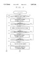
Next, referring to FIGS. 4 and 5, the operation of the driver 34 will be discussed. FIGS. 4 and 5 show operational flow charts of the driver 34.
In step S1, the speed control section 24 decides whether a starting signal to begin a crimping operation is inputted by way of I/O 29-8, and if the decision is NO, the operation does not start until the decision becomes YES.
In step S2, the speed control section 24 reads out a normally accelerated rotating speed of the servo-motor 4 from the data storage section 23, and outputs a signal to the amplifying section 27 by way of I/O 29-1 so that the amplifying section 27 supplies a current to the servo-motor 4 in such way that the servo-motor 4 rotates at the read out accelerated speed.
The values outputted from the rotary encoder 33 by way of I/O 29-3 are differentiated to obtain rotation speeds of the motor and further the rotation speeds are differentiated to determine rotation accelerations of the motor.
In step S3, The speed control section 24 determines whether a value outputted from the rotary encoder 33 by way of I/O 29-3 becomes equal to the value that is stored in the data storage section 23 and corresponds to a position from which a uniform rotation speed begins. If the decision is NO, step S2 continues to accelerate the motor, while if the decision is YES, a following step S4 makes the motor rotate at a uniform speed.
Further, when step S5 in the speed control section 24 detects the arrival at the deceleration starting position of the motor, the following step S8 decelerates the rotation of the motor. The next step S7 decides whether the crimper has reached the terminal crimping position, and if the decision is YES, the step S7 outputs a corresponding signal to the current control section 25.
In the current control section 25, step S8 reads out a current I stored in the data storage section 23 and which is required by the servo-motor 4 just in a crimping stage. The next step S9 corrects the current I based on a temperature outputted from the temperature sensor 31 by way of I/O 29-4 so that the motor torque becomes equal to the reference value. Further, the following step S10 outputs the current I by way of I/O 29-1.
In the decision section 26, step S11 records the decision reference data in a memory (not shown). The decision reference data will be discussed later in detail.
In the current control section 25, step S12 determines whether the servo-motor 4 has received the current I during the time t, and if the decision is NO, the steps S10 and S11 are executed again.
In the speed control section 24, step S13 reversely rotates the servo-motor 4 with a predetermined acceleration, and, if step S14 decides that the motor rotation has reached a uniform speed, the following step S15 controls the motor such that it rotate at the uniform speed. When the next step 16 determines that the crimper has come to the deceleration starting position, the following step S17 decelerates the motor and step S18 stops the motor rotation based on the arrival at a stopping position.
In the decision section 26, step S19 determines whether the latest crimping operation has been normal based on the data recorded in step S11. Then, the following step S20 displays the results in a crimp monitor 21 and also outputs a warning signal in the case of an abnormal crimping operation.
For determining whether the crimping operation is normal, as shown in FIG, 8A, step S11 records current values (driving current), which are detected in the current detecting section 28 and supplied to the servo-motor 4 at a constant time interval.
FIG. 8A shows the driving current supplied to the motor 4 at the crimping operation in FIG. 7B. The current control section 25 controls in such way that standard currents, the values of which are stored in the data storage section, are supplied to the motor. In the motor stopping state, a uniform current is supplied to the motor, while the motor driving current changes when the motor begins to rotate to result in a modified control balance. When a terminal is just crimped, if there are no cores in the cable or if an insulated wire is crimped, the supplied current becomes smaller or larger than the standard current in the normal crimping operation. Accordingly, in the present invention, whether the crimping is normal is decided based on thus changed current supplied to the motor.
Further, FIG. 8B shows an output from the height sensor 32 when a terminal is crimped. Naturally, when a terminal is just crimped, if there are no cores in the cable, or if an insulated wire is crimped, the resulting crimp height outputted at each time interval becomes lower than, or is different from, the normal crimp height. Therefore, in the present invention, whether the crimping is normal is determined based on the thus-changed crimp height.
A first decision method, as shown in FIG. 8A, includes the steps of: reading out a maximum value among driving currents recorded in the step S11 in a predetermined period; determining whether the maximum value is within the standard values stored in the data storage section 23; and determining whether the crimping has been normally carried out based upon whether the maximum value is within the range of the standard values.
A second decision method includes the steps of: recording reference currents during a predetermined period in the data storage section 23; obtaining the differences between the time series current values recorded in the step S11 and the reference currents; and deciding whether the crimping has been normally carried out based upon whether the difference is within a predetermined range.
A third decision method includes the steps of: obtaining the sum of the current values recorded in the step S11 at a constant interval during a predetermined period; and deciding whether the crimping has been normally carried out based upon whether the sum is within a predetermined range.
A fourth decision method includes, as shown in FIG. 8B, the steps of: recording heights outputted from the height sensor 32 by way of I/O 29-5 in data recording of the step S11; obtaining a minimum value among the recorded data; and deciding whether the crimping has been normally carried out based upon whether the minimum value is within a predetermined range.
A fifth decision method includes the steps of: recording heights outputted from the height sensor 32; obtaining a minimum value among the recorded data; and comparing the time series heights with the corresponding reference values, and deciding whether the crimping has been normally carried out based upon whether the differences are within a predetermined range.
Moreover, the decision may be carried out based on both the driving current and the crimper height.
In the embodiment of the present invention, as mentioned above, the off-center pin 8 pivots within the range of 0 to 180 degrees and a crimp height (the lowest position of the crimper 14) is adjusted by the pivoting range of the off-center pin 8. That is, random adjustments of crimp height are capable by controlling the number of rotatione in the servo-motor 4 by the driver control device 34.
Further, monitoring load currents I in the servo-motor 4 or monitoring the height of the crimper 14 can determine whether the crimping operation is normal or not, that is, whether a product is non-defective during crimping operation. Moreover, a stopping period t is provided in crimping operation so that the terminal barrel is prevented from its spring-back, resulting in reliable stable crimping and reliable products.
In the above-mentioned crimping method, the normally and reversely rotating electrical servo-motor 4 is adopted to vertically reciprocate the crimper 14, the electrical servo-motor may be replaced by a hydrostatic servo-motor.
Claims (9)
1. An apparatus for crimping a terminal to a stripped electrical wire comprising:
a vertically reciprocatable crimper operative to crimp the terminal to conductors of said wire;
an anvil opposing said crimper; and
means for vertically reciprocating said crimper with respect to said anvil including:
a vertically movable ram connected to said crimper,
a piston-crank mechanism for driving said ram,
a circular plate mounted for rotation and connecting said piston-crank mechanism for vertical reciprocating movement upon rotation of said circular plate in forward and reverse directions,
means for driving said circular plate in alternate forward and reverse directions including a servo-motor and a reduction gear connected between said servo-motor and said circular plate; and
a control means including means for stopping said servo-motor during a given time period when said crimper is positioned at its lowest position.
2. The apparatus as claimed in claim 1,
wherein said circular plate has an off-center pin and a crank arm, one end of which is pivotably attached to said off-center pin and the other end of which is pivotably attached to said ram.
3. The apparatus as claimed in claim 1,
wherein said circular plate is operative to pivot forwardly and reversely within an angular range of 0 to 180 degrees by the rotation of said servo-motor.
4. The apparatus as claimed in claim 1, wherein the lowest position of said crimper is determined by a predetermined pivoting angle of said circular plate to adjust a crimp height for the terminal.
5. The apparatus as claimed in claim 4, wherein the predetermined pivoting angle of said circular plate is between 150 to 180 degrees.
6. The apparatus as claimed in claim 1, further comprising a control means operative to control the rotating speed of said servo-motor, said control means including means for decelerating said servo-motor prior to engagement of said crimper with said terminal, means for stopping said servo-motor during said given time period at the lowest position of said crimper; and means for reversely rotating said servo-motor to return said crimper to its top position.
7. The apparatus as claimed in claim 1, further comprising
means for comparing a load current applied to said servo-motor with an upper or lower limit of reference load currents.
8. The apparatus as claimed in claim 7, further comprising
a temperature correction means operative to detect a temperature of a motor coil of said servo-motor and means for correcting said load current applied to said servo-motor in response to a correction obtained by comparing a detected temperature to a corresponding load current in a reference temperature.
9. The apparatus as claimed in claim 1, further comprising
a speed control means operative to control vertically reciprocating speeds of said crimper, said speed control means including a rotary encoder attached to a rotation axis of said servo-motor, and a position-detecting means for detecting positions of said crimper based on a detected number of rotations of said rotary encoder; and
means controlling said vertically reciprocating speeds of said crimper based on a comparison of the position detected by said position-detecting means to predetermined reference speeds.
Applications Claiming Priority (2)
| Application Number | Priority Date | Filing Date | Title |
|---|---|---|---|
| JP32882594 | 1994-12-28 | ||
| JP6-328825 | 1994-12-28 |
Publications (1)
| Publication Number | Publication Date |
|---|---|
| US5697146A true US5697146A (en) | 1997-12-16 |
Family
ID=18214512
Family Applications (1)
| Application Number | Title | Priority Date | Filing Date |
|---|---|---|---|
| US08/576,083 Expired - Lifetime US5697146A (en) | 1994-12-28 | 1995-12-21 | Apparatus for crimping terminal to electrical wire |
Country Status (5)
| Country | Link |
|---|---|
| US (1) | US5697146A (en) |
| KR (1) | KR100216309B1 (en) |
| CN (1) | CN1041475C (en) |
| DE (1) | DE19548534B4 (en) |
| MX (1) | MX9600169A (en) |
Cited By (13)
| Publication number | Priority date | Publication date | Assignee | Title |
|---|---|---|---|---|
| US5819570A (en) * | 1996-10-30 | 1998-10-13 | Nichifu Terminal Manufacture | Motor driven portable crimper having a detection mechanism to automatically turn off the motor |
| US5887469A (en) * | 1996-07-31 | 1999-03-30 | Yazaki Corporation | Terminal crimping device |
| US5921125A (en) * | 1996-06-12 | 1999-07-13 | Yazaki Corporation | Control method of terminal crimping device |
| US6276052B1 (en) * | 1999-08-26 | 2001-08-21 | The Whitaker Corporation | Applicator seating sensor |
| US6581427B2 (en) * | 2000-01-24 | 2003-06-24 | Beyeler Raskin S.A. | Method of adjusting the stroke of a press brake |
| US6619088B1 (en) * | 2000-10-16 | 2003-09-16 | Aida Engineering Co., Ltd. | Bottom dead center correction device for servo press machine |
| US6662620B1 (en) | 2000-09-12 | 2003-12-16 | Black & Decker Inc. | Steel stud crimper |
| US20040055354A1 (en) * | 2002-07-17 | 2004-03-25 | Schaefer Werkzeug-Und Sondermaschinen Gmbh | Method and device for quality assurance of crimp joints |
| WO2004056559A1 (en) * | 2002-12-19 | 2004-07-08 | Siemens Aktiengesellschaft | Pressing device |
| DE102006015581B3 (en) * | 2006-04-04 | 2007-10-04 | Aradex Ag | Deformation process implementing method, involves determining temporal sequences of motor current as measure for force or torque of direct drive by integrating measuring device in direct drive |
| US20100319192A1 (en) * | 2009-06-17 | 2010-12-23 | Takahashi Maori | Pressing terminal and terminal pressing device |
| US20150340827A1 (en) * | 2014-05-23 | 2015-11-26 | Tyco Electronics Corporation | Terminal crimping system with wire alignment aid |
| JP2021144817A (en) * | 2020-03-11 | 2021-09-24 | 新明和工業株式会社 | Terminal crimp inspection device and update method for reference waveform of terminal crimp inspection |
Families Citing this family (10)
| Publication number | Priority date | Publication date | Assignee | Title |
|---|---|---|---|---|
| DE10014491A1 (en) * | 2000-03-23 | 2001-09-27 | Grote & Hartmann | Production of crimped wire connections for an electrical cable uses a press tool die set |
| EP1143579A1 (en) * | 2000-04-04 | 2001-10-10 | Pawo Systems A.G. | Contact working station |
| EP1143578A1 (en) * | 2000-04-04 | 2001-10-10 | Pawo Systems A.G. | Contact working station |
| CN1297044C (en) * | 2001-06-15 | 2007-01-24 | 矢崎总业株式会社 | Detection method for terminal crimping state |
| CN103057142B (en) * | 2012-10-18 | 2016-02-03 | 江苏省(扬州)数控机床研究院 | Double-crank drives two point servo-pressing machine |
| CN103862260A (en) * | 2014-03-28 | 2014-06-18 | 德清振达电气有限公司 | Lower die of wire clamping machine |
| CN103872618A (en) * | 2014-03-28 | 2014-06-18 | 德清振达电气有限公司 | Upper mould of lead wire clamping machine |
| CN103878271A (en) * | 2014-03-28 | 2014-06-25 | 德清振达电气有限公司 | Die of micromotor fan wire clamping machine |
| DE102015219701A1 (en) * | 2015-10-12 | 2017-04-13 | Md Elektronik Gmbh | Method for producing an electrical connection between two electrically conductive components and a crimping device |
| CN107732624B (en) * | 2017-09-22 | 2023-07-18 | 鹤壁海昌智能科技股份有限公司 | A driving mechanism of wire harness terminal crimping machine |
Citations (13)
| Publication number | Priority date | Publication date | Assignee | Title |
|---|---|---|---|---|
| DE3540083A1 (en) * | 1985-11-12 | 1987-05-14 | Kirsten Kabeltechnik Ag | Device for stripping electrical cables, and for pressing plugs onto the same |
| JPH03189037A (en) * | 1989-12-05 | 1991-08-19 | Amp Inc | Device for crimping terminal |
| US5046241A (en) * | 1988-08-12 | 1991-09-10 | Ricard Claude F | Processes and devices for mechanically crimping terminals on conducting wires |
| US5069060A (en) * | 1986-12-29 | 1991-12-03 | Mitoshi Ishii | Method of operating press machine and servo controller therefor |
| US5084960A (en) * | 1991-01-24 | 1992-02-04 | Amp Incorporated | Apparatus for terminating wires to terminals |
| US5115735A (en) * | 1989-06-23 | 1992-05-26 | Amp Incorporated | Press with control circuit arrangement |
| US5129317A (en) * | 1989-06-23 | 1992-07-14 | Amp Incorporated | Press driven by an electric motor through reduction gearing |
| JPH0529056A (en) * | 1991-07-18 | 1993-02-05 | Nippon Autom Mach Kk | Terminal crimping automatic adjustment device |
| JPH0529055A (en) * | 1991-07-18 | 1993-02-05 | Nippon Autom Mach Kk | Terminal crimp automatic adjustment device |
| EP0564411A1 (en) * | 1992-04-01 | 1993-10-06 | Kirsten Kabeltechnik Ag | Device for crimping connectors on bets of stripped lines and/or for stripping electrical or optical lines |
| US5271254A (en) * | 1989-12-05 | 1993-12-21 | The Whitaker Corporation | Crimped connector quality control method apparatus |
| JPH0625911A (en) * | 1992-02-18 | 1994-02-01 | Kuraray Co Ltd | Modified ethylene-vinyl alcohol-based copolymer yarn |
| US5517749A (en) * | 1993-09-14 | 1996-05-21 | Molex Incorporated | Electrical terminal applicator with improved crimp height adjustment plate means |
Family Cites Families (7)
| Publication number | Priority date | Publication date | Assignee | Title |
|---|---|---|---|---|
| DE3842009C1 (en) * | 1988-11-22 | 1990-03-22 | Kabelwerke Reinshagen Gmbh, 5600 Wuppertal, De | |
| DE4014221A1 (en) * | 1989-05-12 | 1990-11-15 | Siemens Ag | METHOD AND DEVICE FOR PRODUCTION MONITORING IN CRIMPING FLEXIBLE, STRIPED CORES OF CABLES |
| GB8927467D0 (en) * | 1989-12-05 | 1990-02-07 | Amp Gmbh | Crimped connection quality control |
| DE4040410C1 (en) * | 1989-12-21 | 1991-11-07 | Bernhard Dr.-Ing. 4782 Erwitte De Juergenhake | Tooling for crimping electrical connectors - comprises crank press with spring-loaded plunger, connected torsionally to transducer providing displacement measurement |
| DE3942219C1 (en) * | 1989-12-21 | 1991-02-21 | Bernhard Dr.-Ing. 4782 Erwitte De Juergenhake | Crimped connection quality measurement method - measuring distance positionally fixed tool or press base and active tool or press head |
| GB9012058D0 (en) * | 1990-05-30 | 1990-07-18 | Amp Gmbh | Method of,and apparatus for,controlling the crimp height of crimped electrical connections |
| DE4215163C2 (en) * | 1992-05-08 | 1995-01-05 | Grote & Hartmann | Crimp monitoring method for crimp fault detection and device for carrying out the method |
-
1995
- 1995-12-21 US US08/576,083 patent/US5697146A/en not_active Expired - Lifetime
- 1995-12-22 DE DE19548534A patent/DE19548534B4/en not_active Expired - Lifetime
- 1995-12-28 CN CN95121705A patent/CN1041475C/en not_active Expired - Lifetime
- 1995-12-28 KR KR1019950061338A patent/KR100216309B1/en not_active Expired - Lifetime
-
1996
- 1996-01-09 MX MX9600169A patent/MX9600169A/en unknown
Patent Citations (14)
| Publication number | Priority date | Publication date | Assignee | Title |
|---|---|---|---|---|
| DE3540083A1 (en) * | 1985-11-12 | 1987-05-14 | Kirsten Kabeltechnik Ag | Device for stripping electrical cables, and for pressing plugs onto the same |
| US5079489A (en) * | 1986-12-29 | 1992-01-07 | Mitoshi Ishii | Method of operating press machine and servo controller therefor |
| US5069060A (en) * | 1986-12-29 | 1991-12-03 | Mitoshi Ishii | Method of operating press machine and servo controller therefor |
| US5046241A (en) * | 1988-08-12 | 1991-09-10 | Ricard Claude F | Processes and devices for mechanically crimping terminals on conducting wires |
| US5115735A (en) * | 1989-06-23 | 1992-05-26 | Amp Incorporated | Press with control circuit arrangement |
| US5129317A (en) * | 1989-06-23 | 1992-07-14 | Amp Incorporated | Press driven by an electric motor through reduction gearing |
| JPH03189037A (en) * | 1989-12-05 | 1991-08-19 | Amp Inc | Device for crimping terminal |
| US5271254A (en) * | 1989-12-05 | 1993-12-21 | The Whitaker Corporation | Crimped connector quality control method apparatus |
| US5084960A (en) * | 1991-01-24 | 1992-02-04 | Amp Incorporated | Apparatus for terminating wires to terminals |
| JPH0529056A (en) * | 1991-07-18 | 1993-02-05 | Nippon Autom Mach Kk | Terminal crimping automatic adjustment device |
| JPH0529055A (en) * | 1991-07-18 | 1993-02-05 | Nippon Autom Mach Kk | Terminal crimp automatic adjustment device |
| JPH0625911A (en) * | 1992-02-18 | 1994-02-01 | Kuraray Co Ltd | Modified ethylene-vinyl alcohol-based copolymer yarn |
| EP0564411A1 (en) * | 1992-04-01 | 1993-10-06 | Kirsten Kabeltechnik Ag | Device for crimping connectors on bets of stripped lines and/or for stripping electrical or optical lines |
| US5517749A (en) * | 1993-09-14 | 1996-05-21 | Molex Incorporated | Electrical terminal applicator with improved crimp height adjustment plate means |
Cited By (16)
| Publication number | Priority date | Publication date | Assignee | Title |
|---|---|---|---|---|
| US5921125A (en) * | 1996-06-12 | 1999-07-13 | Yazaki Corporation | Control method of terminal crimping device |
| US5887469A (en) * | 1996-07-31 | 1999-03-30 | Yazaki Corporation | Terminal crimping device |
| US5819570A (en) * | 1996-10-30 | 1998-10-13 | Nichifu Terminal Manufacture | Motor driven portable crimper having a detection mechanism to automatically turn off the motor |
| US6276052B1 (en) * | 1999-08-26 | 2001-08-21 | The Whitaker Corporation | Applicator seating sensor |
| US6581427B2 (en) * | 2000-01-24 | 2003-06-24 | Beyeler Raskin S.A. | Method of adjusting the stroke of a press brake |
| US6662620B1 (en) | 2000-09-12 | 2003-12-16 | Black & Decker Inc. | Steel stud crimper |
| US6619088B1 (en) * | 2000-10-16 | 2003-09-16 | Aida Engineering Co., Ltd. | Bottom dead center correction device for servo press machine |
| US20060198915A1 (en) * | 2002-07-17 | 2006-09-07 | Schaefer Werkzeug- Und Sondermaschinen Gmbh | Method and device for quality assurance of crimp joints |
| US20040055354A1 (en) * | 2002-07-17 | 2004-03-25 | Schaefer Werkzeug-Und Sondermaschinen Gmbh | Method and device for quality assurance of crimp joints |
| WO2004056559A1 (en) * | 2002-12-19 | 2004-07-08 | Siemens Aktiengesellschaft | Pressing device |
| DE102006015581B3 (en) * | 2006-04-04 | 2007-10-04 | Aradex Ag | Deformation process implementing method, involves determining temporal sequences of motor current as measure for force or torque of direct drive by integrating measuring device in direct drive |
| US20100319192A1 (en) * | 2009-06-17 | 2010-12-23 | Takahashi Maori | Pressing terminal and terminal pressing device |
| US8826523B2 (en) * | 2009-06-17 | 2014-09-09 | Hirose Electric Co., Ltd. | Pressing terminal and terminal pressing device |
| US20150340827A1 (en) * | 2014-05-23 | 2015-11-26 | Tyco Electronics Corporation | Terminal crimping system with wire alignment aid |
| US9548580B2 (en) * | 2014-05-23 | 2017-01-17 | Tyco Electronics Corporation | Terminal crimping system with wire alignment aid |
| JP2021144817A (en) * | 2020-03-11 | 2021-09-24 | 新明和工業株式会社 | Terminal crimp inspection device and update method for reference waveform of terminal crimp inspection |
Also Published As
| Publication number | Publication date |
|---|---|
| CN1131834A (en) | 1996-09-25 |
| KR960027086A (en) | 1996-07-22 |
| DE19548534A1 (en) | 1996-07-11 |
| MX9600169A (en) | 1997-01-31 |
| CN1041475C (en) | 1998-12-30 |
| DE19548534B4 (en) | 2005-09-15 |
| KR100216309B1 (en) | 1999-08-16 |
Similar Documents
| Publication | Publication Date | Title |
|---|---|---|
| US5727409A (en) | Method of controlling a terminal crimping apparatus | |
| US5669257A (en) | Method of crimping terminal and apparatus for the same | |
| US5697146A (en) | Apparatus for crimping terminal to electrical wire | |
| US5887469A (en) | Terminal crimping device | |
| US5921125A (en) | Control method of terminal crimping device | |
| US4587725A (en) | Terminal crimping apparatus | |
| US5966806A (en) | Control method of terminal crimping device | |
| EP0397434B1 (en) | Method of, and apparatus for, terminating wires to terminals | |
| US5901440A (en) | Control method of terminal crimping device | |
| JPH08236253A (en) | Control method of terminal crimping device | |
| JPH1158099A (en) | Servo press die protection device and method | |
| US6487885B2 (en) | Method and apparatus for producing a crimped connection | |
| JPH11273823A (en) | Crimp failure detection method for terminal crimping equipment | |
| JPH08236251A (en) | Terminal crimping method and device | |
| JP4008557B2 (en) | Press machine | |
| JP3720099B2 (en) | Method and apparatus for detecting plate thickness in bending machine, bending method and bending machine | |
| JP3107147B2 (en) | Terminal crimping method and equipment | |
| JPH0529055A (en) | Terminal crimp automatic adjustment device | |
| MXPA97005799A (en) | Folding device termi | |
| JPH1158097A (en) | Servo press die protection device and method | |
| JP3492122B2 (en) | Ram control method and control device for press brake | |
| JP2001068245A (en) | Crimp height adjustment method | |
| JPH10247576A (en) | Terminal crimping device | |
| JPH06238341A (en) | Pressure indicating device and pressure alarm checking device in motor-driven bending device | |
| JPH10255948A (en) | Terminal crimping device |
Legal Events
| Date | Code | Title | Description |
|---|---|---|---|
| STCF | Information on status: patent grant |
Free format text: PATENTED CASE |
|
| FPAY | Fee payment |
Year of fee payment: 4 |
|
| FPAY | Fee payment |
Year of fee payment: 8 |
|
| FPAY | Fee payment |
Year of fee payment: 12 |