US5697141A - Method of securing members together - Google Patents
Method of securing members together Download PDFInfo
- Publication number
- US5697141A US5697141A US08/593,335 US59333596A US5697141A US 5697141 A US5697141 A US 5697141A US 59333596 A US59333596 A US 59333596A US 5697141 A US5697141 A US 5697141A
- Authority
- US
- United States
- Prior art keywords
- rivet
- head
- members
- deforming
- die
- Prior art date
- Legal status (The legal status is an assumption and is not a legal conclusion. Google has not performed a legal analysis and makes no representation as to the accuracy of the status listed.)
- Expired - Lifetime
Links
- 238000000034 method Methods 0.000 title claims abstract description 34
- 230000002708 enhancing effect Effects 0.000 claims 4
- 230000006835 compression Effects 0.000 abstract description 4
- 238000007906 compression Methods 0.000 abstract description 4
- 238000004519 manufacturing process Methods 0.000 abstract description 4
- 239000002184 metal Substances 0.000 abstract description 3
- 229910000831 Steel Inorganic materials 0.000 description 3
- 239000010959 steel Substances 0.000 description 3
- 241000167854 Bourreria succulenta Species 0.000 description 2
- 238000003780 insertion Methods 0.000 description 2
- 230000037431 insertion Effects 0.000 description 2
- 230000015572 biosynthetic process Effects 0.000 description 1
- 238000002788 crimping Methods 0.000 description 1
- 238000005553 drilling Methods 0.000 description 1
- 238000009434 installation Methods 0.000 description 1
- 238000012986 modification Methods 0.000 description 1
- 230000004048 modification Effects 0.000 description 1
- 238000004080 punching Methods 0.000 description 1
- 238000005096 rolling process Methods 0.000 description 1
- 238000011179 visual inspection Methods 0.000 description 1
Images


Classifications
-
- F—MECHANICAL ENGINEERING; LIGHTING; HEATING; WEAPONS; BLASTING
- F16—ENGINEERING ELEMENTS AND UNITS; GENERAL MEASURES FOR PRODUCING AND MAINTAINING EFFECTIVE FUNCTIONING OF MACHINES OR INSTALLATIONS; THERMAL INSULATION IN GENERAL
- F16B—DEVICES FOR FASTENING OR SECURING CONSTRUCTIONAL ELEMENTS OR MACHINE PARTS TOGETHER, e.g. NAILS, BOLTS, CIRCLIPS, CLAMPS, CLIPS OR WEDGES; JOINTS OR JOINTING
- F16B19/00—Bolts without screw-thread; Pins, including deformable elements; Rivets
- F16B19/04—Rivets; Spigots or the like fastened by riveting
- F16B19/08—Hollow rivets; Multi-part rivets
- F16B19/10—Hollow rivets; Multi-part rivets fastened by expanding mechanically
- F16B19/1027—Multi-part rivets
- F16B19/1036—Blind rivets
- F16B19/1045—Blind rivets fastened by a pull - mandrel or the like
- F16B19/1054—Blind rivets fastened by a pull - mandrel or the like the pull-mandrel or the like being frangible
-
- F—MECHANICAL ENGINEERING; LIGHTING; HEATING; WEAPONS; BLASTING
- F16—ENGINEERING ELEMENTS AND UNITS; GENERAL MEASURES FOR PRODUCING AND MAINTAINING EFFECTIVE FUNCTIONING OF MACHINES OR INSTALLATIONS; THERMAL INSULATION IN GENERAL
- F16B—DEVICES FOR FASTENING OR SECURING CONSTRUCTIONAL ELEMENTS OR MACHINE PARTS TOGETHER, e.g. NAILS, BOLTS, CIRCLIPS, CLAMPS, CLIPS OR WEDGES; JOINTS OR JOINTING
- F16B5/00—Joining sheets or plates, e.g. panels, to one another or to strips or bars parallel to them
- F16B5/04—Joining sheets or plates, e.g. panels, to one another or to strips or bars parallel to them by means of riveting
-
- Y—GENERAL TAGGING OF NEW TECHNOLOGICAL DEVELOPMENTS; GENERAL TAGGING OF CROSS-SECTIONAL TECHNOLOGIES SPANNING OVER SEVERAL SECTIONS OF THE IPC; TECHNICAL SUBJECTS COVERED BY FORMER USPC CROSS-REFERENCE ART COLLECTIONS [XRACs] AND DIGESTS
- Y10—TECHNICAL SUBJECTS COVERED BY FORMER USPC
- Y10T—TECHNICAL SUBJECTS COVERED BY FORMER US CLASSIFICATION
- Y10T29/00—Metal working
- Y10T29/49—Method of mechanical manufacture
- Y10T29/49826—Assembling or joining
- Y10T29/49947—Assembling or joining by applying separate fastener
- Y10T29/49954—Fastener deformed after application
- Y10T29/49956—Riveting
-
- Y—GENERAL TAGGING OF NEW TECHNOLOGICAL DEVELOPMENTS; GENERAL TAGGING OF CROSS-SECTIONAL TECHNOLOGIES SPANNING OVER SEVERAL SECTIONS OF THE IPC; TECHNICAL SUBJECTS COVERED BY FORMER USPC CROSS-REFERENCE ART COLLECTIONS [XRACs] AND DIGESTS
- Y10—TECHNICAL SUBJECTS COVERED BY FORMER USPC
- Y10T—TECHNICAL SUBJECTS COVERED BY FORMER US CLASSIFICATION
- Y10T29/00—Metal working
- Y10T29/53—Means to assemble or disassemble
- Y10T29/53709—Overedge assembling means
- Y10T29/53717—Annular work
- Y10T29/53726—Annular work with second workpiece inside annular work one workpiece moved to shape the other
- Y10T29/5373—Annular work with second workpiece inside annular work one workpiece moved to shape the other comprising driver for snap-off-mandrel fastener; e.g., Pop [TM] riveter
- Y10T29/53735—Annular work with second workpiece inside annular work one workpiece moved to shape the other comprising driver for snap-off-mandrel fastener; e.g., Pop [TM] riveter including near side fastener shaping tool
-
- Y—GENERAL TAGGING OF NEW TECHNOLOGICAL DEVELOPMENTS; GENERAL TAGGING OF CROSS-SECTIONAL TECHNOLOGIES SPANNING OVER SEVERAL SECTIONS OF THE IPC; TECHNICAL SUBJECTS COVERED BY FORMER USPC CROSS-REFERENCE ART COLLECTIONS [XRACs] AND DIGESTS
- Y10—TECHNICAL SUBJECTS COVERED BY FORMER USPC
- Y10T—TECHNICAL SUBJECTS COVERED BY FORMER US CLASSIFICATION
- Y10T29/00—Metal working
- Y10T29/53—Means to assemble or disassemble
- Y10T29/53709—Overedge assembling means
- Y10T29/5377—Riveter
Definitions
- the invention relates to a method of securing members together.
- it relates to securing sheet-like members together so as to enhance resistance to relative slipping.
- the fastener comprises a shank, which is passed through superposed apertures or holes in the members, and a preformed head at one end of the shank.
- the preformed head abuts one face of the members, and a second head is provided at the other end of the shank.
- the second head is urged towards the preformed head (e.g. by screwing the nut along the bolt, or by deforming the projecting part of the rivet shank) so that the members are clamped together between the two heads. It is relatively easy to develop tension in the fastener shank, so as to hold the members in contact with each other.
- Tolerances in hole size have to be allowed to accommodate inaccuracies in the diameter and positions of the punched holes, and in the relative position of the panels on assembly together. Furthermore, it may be required that the hole in the front panel (i.e. the one nearer the assembly operator) is larger than the hole in the rear panel (i.e. the one further away from the assembly operator), to further facilitate alignment of the holes, and to assist the assembly operator in aligning the holes by visual inspection. Again, it is usually desirable or necessary that both holes are of somewhat larger diameter than the shank of the fastener to be used, to facilitate insertion of the fastener shank into and through the holes. Hence in practice the holes through the members will be oversize to the fastener shank.
- the present invention is intended to overcome this problem, by increasing the resistance to such initial slip.
- the invention provides a method of securing together apertured sheet-like members which are in face to face relationship with superposed apertures, which method comprises the steps of:
- the rivet moving the heads of the rivet towards each other thereby to compress the members between the deforming die and the blind head so as to deform at least one of the members, so that the sheets, around their superposed apertures, are similarly deformed transversely into engagement with each other, the rivet heads maintaining the members in engagement as aforesaid, thereby to enhance resistance to relative slipping movement of the members; in which the rivet is a blind rivet and the deforming die is provided by a head of the blind rivet.
- FIGS. 1A, 1B & 1C show successive stages in a method of securing together of two relatively thin, deformable sheets by means of a blind rivet;
- FIGS. 2A, 2B and 2C correspond to FIGS. 1A, 1B & 1C respectively but also illustrate part of the rivet installation tool used;
- FIGS. 3A, 3B & 3C show successive stages in a method of securing together of a relatively thin, deformable sheet and a relatively thick, stronger sheet;
- FIGS. 4A, 4B & 4C illustrate successive stages on a method of securing together of a relatively thick, strong sheet and a relatively thin, deformable sheet
- FIGS. 5A, 5B, 5C illustrate successive stages in another method of securing together a relatively strong sheet and a relatively deformable one
- FIG. 6A is a perspective view of part of an assembly to which the method shown in FIGS. 5A, 5B & 5C is applied;
- FIG. 6B is a plan view of the assembly.
- FIG. 6C is an enlarged view of part of FIG. 6B.
- the sheet-like members to be formed comprise two relatively thin steel sheets, a front sheet 11 and a rear sheet 12, typically of thickness about 0.7 mm each.
- the rear sheet is provided with a circular pre-punched hole 13
- the front sheet 11 is provided with a circular pre-punched hole 14 of larger diameter than the hole 13.
- the front sheet hole 14 is larger than the rear sheet hole 13 to facilitate alignment of the holes, as previously described.
- the sheets are to be secured together by means of a blind rivet 15.
- the diameter of both holes is larger than that of the rivet shank, as is illustrated in FIG. 1A.
- the blind breakstem rivet is of a type which is generally well known in the art of mechanical assembly, and is generally similar to the rivet widely known and commercially available under the registered trademark AVEX.
- a rivet comprises a steel shell including a tubular shank 16 with an integral radially enlarged preformed head 17 at one end, and a steel stem comprising a plugging portion 18 joined by a breakneck 19 of reduced diameter to a pulling portion 21.
- the stem is formed integrally with an enlarged head 22 which abuts the tail end of the shank 16.
- the remote end pan of the shank 16 axially contracts and buckles radially outwardly to form a blind head, so that the sheets are secured together by compression exerted by the preformed head and the blind head.
- the rivet 15 is inserted through the holes 11 and 12 so that the underside of the shell head 17 abuts the face of the front sheet 11, and the remote end of the shank 16 protrudes from the rear sheet 12, as illustrated in FIG. 1A.
- the tailmost part of the shank 16 contracts axially and expands radially outwardly to form a blind head 23.
- the blind head is in the form of a single bulb of a tapered or partly-conical shape, in which its cross-sectional dimension is smallest adjacent the rear sheet 12 and increases progressively away from the rear sheet 12 and towards the stem head 22. It is well known in the art of designing and manufacturing blind breakstem rivets that the position and shape of the bulbed blind head can be controlled by modifying the configuration of the exterior of the shank, e.g.
- one shank configuration which has been found to produce the blind head shape illustrated FIG. 1B consists of a long crimp in the shank at its tail end (adjacent the stem head) together with a narrow crimp adjacent the shell head 17.
- FIGS. 2A, 2B & 2C illustrate relevant parts of the tool 24. These are an outer tube having at its front end a recessed, tapering outer anvil 25, an inner tube reciprocable to a limited extent within the outer tube and carrying at its front end an annular inner anvil 26, and a reciprocable collet 27 carrying jaws 28 for gripping the pulling portion 21 of the stem.
- the inner anvil 26 is reciprocable with respect to the outer anvil 25, and the collet 27 is reciprocable with respect to both anvils, by means of hydraulic piston and cylinder devices within the tool.
- CHERRY G784 HYDRO-SHIFT RIVETER CHERRY is a registered trademark.
- the G784 tool has the anvils and jaws as described above, and is arranged to place a blind rivet by first contacting the rivet head with the outer anvil 25 and retracting the jaws 28 to pull the rivet stem, and then advancing the inner anvil 26 with respect to the jaws to actuate a locking device on the rivet.
- the tool 24 of the present example is a G784 tool which has been modified so that the sequence of operation of the inner and outer anvils is reversed.
- the inner anvil 26 is first advanced to contact the rivet preformed head 17 at a first zone around and adjacent the stem pulling portion 21, as illustrated in FIG. 2A.
- the collet 27 is then retracted to pull the rivet stem while supporting the reaction to this on the aforesaid zone of the rivet head. This causes formation of the blind head 23 of the rivet, as illustrated in FIGS. 1B and 2B.
- Continued operation of the tool then advances the outer anvil 25 with respect to the inner anvil 26, and collet 27, while still pulling the stem by means of the collet 27 and jaws 28.
- the outer anvil 25 contacts the shell head 17 at a zone radially outwardly and nearer its periphery, the result is that the head 17 of the rivet shell deforms so that while its radially outer periphery remains in contact with and supported by the front sheet 11, the radially more inward part of the head bends upwardly into the outer anvil 25.
- the area of the sheets around the two holes 11, 12 is thus deformed between a convex die, provided by the tapering blind head 23 of the rivet, and a concave die, provided by the concave underside of the shell head 17.
- the underside of the shell head becomes increasingly more concave as the rivet stem is pulled further into the shell, until a position similar to that illustrated in FIG. 2C is reached.
- Continued increase of tension applied to the pulling portion 21 of the stem results in the breakneck 19 fracturing, and the tool and broken-off pulling portion 21 are removed, leaving the rivet installed in, and securing together, the two sheets.
- FIGS. 1A, 1B, 1C and 2A, 2B and 2C The example method of securing sheets together illustrated in FIGS. 1A, 1B, 1C and 2A, 2B and 2C is appropriate where the sheets are both relatively thin and are capable of sufficient deformation by the forces which can be applied by the rivet blind head and rivet preformed head.
- a second example method may be employed. This is a variation of the first example method in which the stronger sheet is used to provide one of the deforming dies,
- FIGS. 3A, 3B & 3C illustrate a method which may be employed when the front sheet 31 is thicker and stronger.
- This method provides the concave die by a countersink 32, around the front sheet hole 14, in the rear face of the front sheet and facing towards the rear sheet 12.
- the rivet is placed in the same way as in the first example, by means of the same tool (not shown), a similar blind head 23 being formed as shown in FIG. 3B.
- the part of the rear sheet 12 around the hole 13 is then deformed by the blind head 23 into the countersink 32, as illustrated in FIG. 3C.
- this example Since the total sheet thickness (known as the grip length) in this example is greater than in the first example, and moreover the zone of the front sheet which the outer periphery of the shell head contacts is not displaced away from the shell head, this example must employ a rivet which is longer than the rivet in the first example.
- a third example method may be employed, in which the convex die may be provided by a preformed deformation of the rear sheet, as illustrated in FIGS. 4A, 4B & 4C.
- the rear sheet is deformed around its hole 13, to provide a tapering front surface 34 as the convex die, on the front face of the rear sheet 33 and facing towards the front sheet 11.
- the rivet blind head 23 is received within the corresponding concavity in the rear sheet as illustrated in FIG. 4B, and thereafter the preformed head of the rivet shell acts to deform the front sheet over the tapering surface 34, as illustrated in FIG. 4C.
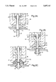
- FIGS. 5A, 5B, 5C, 6A, 6B & 6C A further example of the method is illustrated in FIGS. 5A, 5B, 5C, 6A, 6B & 6C.
- a rivet is first installed in one sheet, leaving the stem, together with an undeformed part of the rivet preformed head, protruding from the front face of the sheet.
- An appropriate part of a second sheet is then positioned between the aforesaid part of the head and the first sheet. That part of the head is then deformed to secure the second sheet to the first.
- the rivet 35 (FIG. 5A) has a preformed head with a shoulder 36 facing towards the sheet 37, which is predeformed to provide a convex die surface 34 around the hole 13.
- the preformed head of the rivet includes a flange 39 which is directed radially outwardly and also away from the blind head.
- the shoulder 36 engages the sheet 37 around the hole's periphery, and together with the blind head 38 secures the rivet to the sheet 37, but without the flange 39 being deformed and without the pulling portion of the stem being broken off (FIG. 5A). This is achieved by positioning the afore-described placing tool over the protruding rivet stem and actuating the tool to perform only the first operation previously illustrated, using the radially inner anvil.
- a second sheet 11 is then inserted between the flange 39 and the sheet 37, as illustrated in FIG. 5B. This may be done as illustrated in FIGS. 6B & 6C.
- a keyhole slot 41 is provided on the sheet 11, having an enlarged hole part 42 which is large enough to pass over the rivet head flange 39, joined to a slot pan 43 which is narrow enough to be trapped by the flange 39.
- the enlarged hole part 42 is passed over the protruding rivet stem 21 and over the flange 39, and the sheet 11 is slid sideways so that the slot part 43 engages under the flange 39, as illustrated in FIGS. 5B and 6C.
- the placing tool is then offered up to the protruding rivet stem and the securing completed by actuating the tool to perform the second operation as previously described, using the radially outer anvil. This deforms the flange 39 towards the concave die surface provided by the raised surface 34 of the first sheet in order to secure the second sheet 11 to the first sheet 37.
- the pulling portion of the rivet stem is then broken off, leaving the two sheets secured together, as illustrated in FIG. 5C.
- FIGS. 6A, 6B & 6C illustrate a particular application of this example method, in which three rivets are provided in triangular relationship on one sheet which is part of an assembly, and a corresponding three keyhole slots are provided on the second sheet, which is thereby secured to the assembly.
- the blind head formed on the rivet shank may have a different configuration.
- it could be formed of two bulbs of different diameters, the smaller diameter one nearer the preformed head and the larger diameter one more remote from the preformed head. More than two bulbs of such graded diameters could be employed.
Landscapes
- Engineering & Computer Science (AREA)
- General Engineering & Computer Science (AREA)
- Mechanical Engineering (AREA)
- Insertion Pins And Rivets (AREA)
- Connection Of Plates (AREA)
- Joining Of Building Structures In Genera (AREA)
- Dicing (AREA)
- Purses, Travelling Bags, Baskets, Or Suitcases (AREA)
Applications Claiming Priority (2)
| Application Number | Priority Date | Filing Date | Title |
|---|---|---|---|
| GB9501866 | 1995-01-31 | ||
| GB9501866A GB2297508A (en) | 1995-01-31 | 1995-01-31 | Method of riveting and blind rivet |
Publications (1)
| Publication Number | Publication Date |
|---|---|
| US5697141A true US5697141A (en) | 1997-12-16 |
Family
ID=10768860
Family Applications (1)
| Application Number | Title | Priority Date | Filing Date |
|---|---|---|---|
| US08/593,335 Expired - Lifetime US5697141A (en) | 1995-01-31 | 1996-01-29 | Method of securing members together |
Country Status (11)
| Country | Link |
|---|---|
| US (1) | US5697141A (de) |
| EP (1) | EP0725217B1 (de) |
| JP (1) | JP3827169B2 (de) |
| KR (1) | KR960029645A (de) |
| AT (1) | ATE192828T1 (de) |
| AU (1) | AU696017B2 (de) |
| BR (1) | BR9600272A (de) |
| CA (1) | CA2168198A1 (de) |
| DE (1) | DE69608146T2 (de) |
| ES (1) | ES2150070T3 (de) |
| GB (1) | GB2297508A (de) |
Cited By (4)
| Publication number | Priority date | Publication date | Assignee | Title |
|---|---|---|---|---|
| US20030226249A1 (en) * | 2002-06-10 | 2003-12-11 | Schnabel John David | Riveting method |
| US20040045147A1 (en) * | 2001-12-04 | 2004-03-11 | Swanstrom Kenneth A. | Resilient standoff fastener |
| WO2009094775A1 (en) * | 2008-01-29 | 2009-08-06 | Magna Seating Inc. | Conic flange pivot joint |
| US20150063944A1 (en) * | 2013-08-28 | 2015-03-05 | Pem Management, Inc. | Fastener with a Belleville Head |
Families Citing this family (4)
| Publication number | Priority date | Publication date | Assignee | Title |
|---|---|---|---|---|
| GB2330390B (en) * | 1997-10-10 | 2001-10-17 | Avdel Textron Ltd | Blind riveting |
| DE102009003177B4 (de) * | 2009-05-18 | 2014-02-13 | Peter Lazic Gmbh | Implantat zur Fixierung nebeneinander angeordneter Knochenplatten |
| JP6670475B2 (ja) * | 2016-06-13 | 2020-03-25 | 株式会社Gsユアサ | 蓄電素子 |
| RU2769143C1 (ru) * | 2021-01-29 | 2022-03-28 | Владимир Александрович Грибановский | Заклёпка и способ получения неразъёмного заклёпочного соединения деталей, не имеющих двухстороннего подхода к заклепочному шву |
Citations (9)
| Publication number | Priority date | Publication date | Assignee | Title |
|---|---|---|---|---|
| GB368712A (en) * | 1930-12-08 | 1932-03-08 | A E Jenks And Cattell Ltd | Improvements in conveyors used for conveying coal and for like purposes |
| GB427843A (en) * | 1934-03-20 | 1935-05-01 | George Geach Parnall | An improved method of making rivetted connections |
| US2047341A (en) * | 1934-07-19 | 1936-07-14 | Curtiss Aeroplane & Motor Co | Method of riveting |
| GB454733A (en) * | 1935-06-04 | 1936-10-07 | May Claude Hector | Improvements relating to rivetted joints |
| US2397111A (en) * | 1942-08-10 | 1946-03-26 | Huxon Holding Corp | Rivet |
| US4112811A (en) * | 1977-04-15 | 1978-09-12 | John Olmsted King | Self-dimpling fastener pin |
| GB2157788A (en) * | 1984-04-11 | 1985-10-30 | Anthony John Nield | Anchoring devices |
| US4639175A (en) * | 1984-05-15 | 1987-01-27 | Phillips Plastics Corp. | Self-sealing expansion rivet assembly |
| US4897004A (en) * | 1986-06-26 | 1990-01-30 | Textron, Inc. | Blind fastener with self-locking collar |
Family Cites Families (1)
| Publication number | Priority date | Publication date | Assignee | Title |
|---|---|---|---|---|
| NL57311C (de) * |
-
1995
- 1995-01-31 GB GB9501866A patent/GB2297508A/en not_active Withdrawn
-
1996
- 1996-01-26 CA CA002168198A patent/CA2168198A1/en not_active Abandoned
- 1996-01-26 ES ES96300584T patent/ES2150070T3/es not_active Expired - Lifetime
- 1996-01-26 AT AT96300584T patent/ATE192828T1/de not_active IP Right Cessation
- 1996-01-26 DE DE69608146T patent/DE69608146T2/de not_active Expired - Lifetime
- 1996-01-26 EP EP96300584A patent/EP0725217B1/de not_active Expired - Lifetime
- 1996-01-29 US US08/593,335 patent/US5697141A/en not_active Expired - Lifetime
- 1996-01-30 AU AU42270/96A patent/AU696017B2/en not_active Ceased
- 1996-01-30 BR BR9600272A patent/BR9600272A/pt not_active Application Discontinuation
- 1996-01-30 JP JP01447196A patent/JP3827169B2/ja not_active Expired - Fee Related
- 1996-01-31 KR KR19960002354A patent/KR960029645A/ko not_active Application Discontinuation
Patent Citations (9)
| Publication number | Priority date | Publication date | Assignee | Title |
|---|---|---|---|---|
| GB368712A (en) * | 1930-12-08 | 1932-03-08 | A E Jenks And Cattell Ltd | Improvements in conveyors used for conveying coal and for like purposes |
| GB427843A (en) * | 1934-03-20 | 1935-05-01 | George Geach Parnall | An improved method of making rivetted connections |
| US2047341A (en) * | 1934-07-19 | 1936-07-14 | Curtiss Aeroplane & Motor Co | Method of riveting |
| GB454733A (en) * | 1935-06-04 | 1936-10-07 | May Claude Hector | Improvements relating to rivetted joints |
| US2397111A (en) * | 1942-08-10 | 1946-03-26 | Huxon Holding Corp | Rivet |
| US4112811A (en) * | 1977-04-15 | 1978-09-12 | John Olmsted King | Self-dimpling fastener pin |
| GB2157788A (en) * | 1984-04-11 | 1985-10-30 | Anthony John Nield | Anchoring devices |
| US4639175A (en) * | 1984-05-15 | 1987-01-27 | Phillips Plastics Corp. | Self-sealing expansion rivet assembly |
| US4897004A (en) * | 1986-06-26 | 1990-01-30 | Textron, Inc. | Blind fastener with self-locking collar |
Cited By (7)
| Publication number | Priority date | Publication date | Assignee | Title |
|---|---|---|---|---|
| US20040045147A1 (en) * | 2001-12-04 | 2004-03-11 | Swanstrom Kenneth A. | Resilient standoff fastener |
| US20030226249A1 (en) * | 2002-06-10 | 2003-12-11 | Schnabel John David | Riveting method |
| US6751841B2 (en) * | 2002-06-10 | 2004-06-22 | Sun Microsystems, Inc. | Riveting method |
| US6877204B1 (en) * | 2002-06-10 | 2005-04-12 | Sun Microsystems, Inc. | Riveting method |
| WO2009094775A1 (en) * | 2008-01-29 | 2009-08-06 | Magna Seating Inc. | Conic flange pivot joint |
| US20150063944A1 (en) * | 2013-08-28 | 2015-03-05 | Pem Management, Inc. | Fastener with a Belleville Head |
| US9816545B2 (en) * | 2013-08-28 | 2017-11-14 | Pem Management, Inc. | Fastener with a Belleville head |
Also Published As
| Publication number | Publication date |
|---|---|
| ATE192828T1 (de) | 2000-05-15 |
| EP0725217B1 (de) | 2000-05-10 |
| KR960029645A (de) | 1996-08-17 |
| ES2150070T3 (es) | 2000-11-16 |
| GB2297508A (en) | 1996-08-07 |
| GB9501866D0 (en) | 1995-03-22 |
| JP3827169B2 (ja) | 2006-09-27 |
| AU4227096A (en) | 1996-08-08 |
| DE69608146T2 (de) | 2001-01-25 |
| DE69608146D1 (de) | 2000-06-15 |
| BR9600272A (pt) | 1997-12-23 |
| EP0725217A1 (de) | 1996-08-07 |
| JPH08232928A (ja) | 1996-09-10 |
| CA2168198A1 (en) | 1996-08-01 |
| AU696017B2 (en) | 1998-08-27 |
Similar Documents
| Publication | Publication Date | Title |
|---|---|---|
| EP1141560B1 (de) | Blindbefestiger | |
| EP0539793B1 (de) | Verfahren zum Anbringen eines Verbindungselementes auf eine Platte und Kombination einer Platte und wenigstens eines Verbindungselementes | |
| JP3346566B2 (ja) | 改良されたパネルクリンチング方法 | |
| EP2490838B1 (de) | Klammerstifthalterung | |
| EP1623126B1 (de) | Blindbefestiger und verfahren zur dessen entfernung von einem werkstück | |
| US6081984A (en) | Method of fastening members of an assembly | |
| EP1021260B1 (de) | Blindnieten | |
| US5697141A (en) | Method of securing members together | |
| EP1327082B1 (de) | Blindbefestiger | |
| US4112811A (en) | Self-dimpling fastener pin | |
| EP0728950A1 (de) | Verfahren zum Verbinden von zwei Bauteilen und Befestigungsvorrichtung dafür | |
| US6842962B1 (en) | Sheet joining method and apparatus and a rivet for use in the method | |
| GB2401662A (en) | Removable blind rivet |
Legal Events
| Date | Code | Title | Description |
|---|---|---|---|
| AS | Assignment |
Owner name: AVDEL TEXTRON LIMITED, ENGLAND Free format text: ASSIGNMENT OF ASSIGNORS INTEREST;ASSIGNORS:DENHAM, KEITH;SHERRY, NEIL JAMES;REEL/FRAME:007898/0602 Effective date: 19960319 |
|
| STCF | Information on status: patent grant |
Free format text: PATENTED CASE |
|
| FPAY | Fee payment |
Year of fee payment: 4 |
|
| FPAY | Fee payment |
Year of fee payment: 8 |
|
| AS | Assignment |
Owner name: U.S. BANK NATIONAL ASSOCIATION, AS COLLATERAL AGEN Free format text: SECURITY AGREEMENT;ASSIGNORS:CAMCAR INTELLECTUAL PROPERTIES, LLC;KING HOLDING CORPORATION;KING HOLDING US CORPORATION;AND OTHERS;REEL/FRAME:018806/0296 Effective date: 20060811 Owner name: WELLS FARGO FOOTHILL, INC., AS COLLATERAL AGENT, C Free format text: SECURITY AGREEMENT;ASSIGNORS:CAMCAR INTELLECTUAL PROPERTIES, LLC;KING HOLDING CORPORATION;KING HOLDING US CORPORATION;AND OTHERS;REEL/FRAME:018806/0538 Effective date: 20060811 Owner name: CREDIT SUISSE, CAYMAN ISLANDS BRANCH, AS COLLATERA Free format text: SECURITY AGREEMENT;ASSIGNORS:CAMCAR INTELLECTUAL PROPERTIES, LLC;KING HOLDING CORPORATION;KING HOLDING US CORPORATION;AND OTHERS;REEL/FRAME:018806/0167 Effective date: 20060811 |
|
| FPAY | Fee payment |
Year of fee payment: 12 |
|
| AS | Assignment |
Owner name: ELCO FASTENING SYSTEMS LLC, MICHIGAN Free format text: RELEASE OF SECURITY AGREEMENT;ASSIGNORS:CREDIT SUISSE, CAYMAN ISLANDS BRANCH, AS COLLATERAL AGENT;WILMINGTON TRUST FSB, AS COLLATERAL AGENT;REEL/FRAME:023273/0086 Effective date: 20090901 Owner name: CAMCAR LLC, RHODE ISLAND Free format text: RELEASE OF SECURITY AGREEMENT;ASSIGNORS:CREDIT SUISSE, CAYMAN ISLANDS BRANCH, AS COLLATERAL AGENT;WILMINGTON TRUST FSB, AS COLLATERAL AGENT;REEL/FRAME:023273/0086 Effective date: 20090901 Owner name: TFS FASTENING SYSTEMS LLC, MICHIGAN Free format text: RELEASE OF SECURITY AGREEMENT;ASSIGNORS:CREDIT SUISSE, CAYMAN ISLANDS BRANCH, AS COLLATERAL AGENT;WILMINGTON TRUST FSB, AS COLLATERAL AGENT;REEL/FRAME:023273/0086 Effective date: 20090901 Owner name: RING SCREW LLC, MICHIGAN Free format text: RELEASE OF SECURITY AGREEMENT;ASSIGNORS:CREDIT SUISSE, CAYMAN ISLANDS BRANCH, AS COLLATERAL AGENT;WILMINGTON TRUST FSB, AS COLLATERAL AGENT;REEL/FRAME:023273/0086 Effective date: 20090901 Owner name: CAMCAR INTELLECTUAL PROPERTIES, LLC, CALIFORNIA Free format text: RELEASE OF SECURITY AGREEMENT;ASSIGNORS:CREDIT SUISSE, CAYMAN ISLANDS BRANCH, AS COLLATERAL AGENT;WILMINGTON TRUST FSB, AS COLLATERAL AGENT;REEL/FRAME:023273/0086 Effective date: 20090901 Owner name: CHERRY AEROSPACE LLC, RHODE ISLAND Free format text: RELEASE OF SECURITY AGREEMENT;ASSIGNORS:CREDIT SUISSE, CAYMAN ISLANDS BRANCH, AS COLLATERAL AGENT;WILMINGTON TRUST FSB, AS COLLATERAL AGENT;REEL/FRAME:023273/0086 Effective date: 20090901 Owner name: FLEXALLOY INC., MICHIGAN Free format text: RELEASE OF SECURITY AGREEMENT;ASSIGNORS:CREDIT SUISSE, CAYMAN ISLANDS BRANCH, AS COLLATERAL AGENT;WILMINGTON TRUST FSB, AS COLLATERAL AGENT;REEL/FRAME:023273/0086 Effective date: 20090901 Owner name: BURKLAND TEXTRON INC., MICHIGAN Free format text: RELEASE OF SECURITY AGREEMENT;ASSIGNORS:CREDIT SUISSE, CAYMAN ISLANDS BRANCH, AS COLLATERAL AGENT;WILMINGTON TRUST FSB, AS COLLATERAL AGENT;REEL/FRAME:023273/0086 Effective date: 20090901 Owner name: WOLVERINE METAL SPECIALTIES, INC., MICHIGAN Free format text: RELEASE OF SECURITY AGREEMENT;ASSIGNORS:CREDIT SUISSE, CAYMAN ISLANDS BRANCH, AS COLLATERAL AGENT;WILMINGTON TRUST FSB, AS COLLATERAL AGENT;REEL/FRAME:023273/0086 Effective date: 20090901 Owner name: KING HOLDING CORPORATION, MASSACHUSETTS Free format text: RELEASE OF SECURITY AGREEMENT;ASSIGNORS:CREDIT SUISSE, CAYMAN ISLANDS BRANCH, AS COLLATERAL AGENT;WILMINGTON TRUST FSB, AS COLLATERAL AGENT;REEL/FRAME:023273/0086 Effective date: 20090901 Owner name: AVDEL CHERRY LLC, MICHIGAN Free format text: RELEASE OF SECURITY AGREEMENT;ASSIGNORS:CREDIT SUISSE, CAYMAN ISLANDS BRANCH, AS COLLATERAL AGENT;WILMINGTON TRUST FSB, AS COLLATERAL AGENT;REEL/FRAME:023273/0086 Effective date: 20090901 Owner name: KING HOLDING US CORPORATION, CALIFORNIA Free format text: RELEASE OF SECURITY AGREEMENT;ASSIGNORS:CREDIT SUISSE, CAYMAN ISLANDS BRANCH, AS COLLATERAL AGENT;WILMINGTON TRUST FSB, AS COLLATERAL AGENT;REEL/FRAME:023273/0086 Effective date: 20090901 |
|
| AS | Assignment |
Owner name: BURKLAND TEXTRON INC., MICHIGAN Free format text: RELEASE OF SECURITY INTEREST;ASSIGNOR:WELLS FARGO FOOTHILL, INC., AS COLLATERAL AGENT;REEL/FRAME:023273/0891 Effective date: 20090901 Owner name: CAMCAR LLC, RHODE ISLAND Free format text: RELEASE OF SECURITY INTEREST;ASSIGNOR:WELLS FARGO FOOTHILL, INC., AS COLLATERAL AGENT;REEL/FRAME:023273/0891 Effective date: 20090901 Owner name: AVDEL CHERRY LLC, MICHIGAN Free format text: RELEASE OF SECURITY INTEREST;ASSIGNOR:WELLS FARGO FOOTHILL, INC., AS COLLATERAL AGENT;REEL/FRAME:023273/0891 Effective date: 20090901 Owner name: CAMCAR INTELLECTUAL PROPERTIES, LLC, CALIFORNIA Free format text: RELEASE OF SECURITY INTEREST;ASSIGNOR:WELLS FARGO FOOTHILL, INC., AS COLLATERAL AGENT;REEL/FRAME:023273/0891 Effective date: 20090901 Owner name: KING HOLDING US CORPORATION, CALIFORNIA Free format text: RELEASE OF SECURITY INTEREST;ASSIGNOR:WELLS FARGO FOOTHILL, INC., AS COLLATERAL AGENT;REEL/FRAME:023273/0891 Effective date: 20090901 Owner name: RING SCREW LLC, MICHIGAN Free format text: RELEASE OF SECURITY INTEREST;ASSIGNOR:WELLS FARGO FOOTHILL, INC., AS COLLATERAL AGENT;REEL/FRAME:023273/0891 Effective date: 20090901 Owner name: CHERRY AEROSPACE LLC, RHODE ISLAND Free format text: RELEASE OF SECURITY INTEREST;ASSIGNOR:WELLS FARGO FOOTHILL, INC., AS COLLATERAL AGENT;REEL/FRAME:023273/0891 Effective date: 20090901 Owner name: FLEXALLOY INC., MICHIGAN Free format text: RELEASE OF SECURITY INTEREST;ASSIGNOR:WELLS FARGO FOOTHILL, INC., AS COLLATERAL AGENT;REEL/FRAME:023273/0891 Effective date: 20090901 Owner name: TFS FASTENING SYSTEMS LLC, MICHIGAN Free format text: RELEASE OF SECURITY INTEREST;ASSIGNOR:WELLS FARGO FOOTHILL, INC., AS COLLATERAL AGENT;REEL/FRAME:023273/0891 Effective date: 20090901 Owner name: KING HOLDING CORPORATION, MASSACHUSETTS Free format text: RELEASE OF SECURITY INTEREST;ASSIGNOR:WELLS FARGO FOOTHILL, INC., AS COLLATERAL AGENT;REEL/FRAME:023273/0891 Effective date: 20090901 Owner name: ELCO FASTENING SYSTEMS LLC, MICHIGAN Free format text: RELEASE OF SECURITY INTEREST;ASSIGNOR:WELLS FARGO FOOTHILL, INC., AS COLLATERAL AGENT;REEL/FRAME:023273/0891 Effective date: 20090901 Owner name: WOLVERINE METAL SPECIALTIES, INC., MICHIGAN Free format text: RELEASE OF SECURITY INTEREST;ASSIGNOR:WELLS FARGO FOOTHILL, INC., AS COLLATERAL AGENT;REEL/FRAME:023273/0891 Effective date: 20090901 |
|
| AS | Assignment |
Owner name: KING HOLDING CORPORATION, MICHIGAN Free format text: RELEASE OF PATENT SECURITY INTEREST;ASSIGNOR:WILMINGTON TRUST FSB, AS THE AGENT;REEL/FRAME:024776/0651 Effective date: 20100803 Owner name: ELCO FASTENING SYSTEMS LLC, MICHIGAN Free format text: RELEASE OF PATENT SECURITY INTEREST;ASSIGNOR:WILMINGTON TRUST FSB, AS THE AGENT;REEL/FRAME:024776/0651 Effective date: 20100803 Owner name: CAMCAR LLC, MICHIGAN Free format text: RELEASE OF PATENT SECURITY INTEREST;ASSIGNOR:WILMINGTON TRUST FSB, AS THE AGENT;REEL/FRAME:024776/0651 Effective date: 20100803 Owner name: SATURN FASTENERS, INC., MICHIGAN Free format text: RELEASE OF PATENT SECURITY INTEREST;ASSIGNOR:WILMINGTON TRUST FSB, AS THE AGENT;REEL/FRAME:024776/0651 Effective date: 20100803 Owner name: FLEXALLOY, INC., MICHIGAN Free format text: RELEASE OF PATENT SECURITY INTEREST;ASSIGNOR:WILMINGTON TRUST FSB, AS THE AGENT;REEL/FRAME:024776/0651 Effective date: 20100803 Owner name: ACUMENT INTELLECTUAL PROPERTIES, LLC, MICHIGAN Free format text: RELEASE OF PATENT SECURITY INTEREST;ASSIGNOR:WILMINGTON TRUST FSB, AS THE AGENT;REEL/FRAME:024776/0651 Effective date: 20100803 Owner name: KING HOLDING US CORPORATION, MICHIGAN Free format text: RELEASE OF PATENT SECURITY INTEREST;ASSIGNOR:WILMINGTON TRUST FSB, AS THE AGENT;REEL/FRAME:024776/0651 Effective date: 20100803 Owner name: ACUMENT GLOBAL TECHNOLOGIES, INC., MICHIGAN Free format text: RELEASE OF PATENT SECURITY INTEREST;ASSIGNOR:WILMINGTON TRUST FSB, AS THE AGENT;REEL/FRAME:024776/0651 Effective date: 20100803 Owner name: RING SCREW LLC, MICHIGAN Free format text: RELEASE OF PATENT SECURITY INTEREST;ASSIGNOR:WILMINGTON TRUST FSB, AS THE AGENT;REEL/FRAME:024776/0651 Effective date: 20100803 Owner name: ACUMENT FASTENING SYSTEMS LLC, MICHIGAN Free format text: RELEASE OF PATENT SECURITY INTEREST;ASSIGNOR:WILMINGTON TRUST FSB, AS THE AGENT;REEL/FRAME:024776/0651 Effective date: 20100803 Owner name: WOLVERINE METAL SPECIALTIES, INC., MICHIGAN Free format text: RELEASE OF PATENT SECURITY INTEREST;ASSIGNOR:WILMINGTON TRUST FSB, AS THE AGENT;REEL/FRAME:024776/0651 Effective date: 20100803 Owner name: AVDEL USA LLC, MICHIGAN Free format text: RELEASE OF PATENT SECURITY INTEREST;ASSIGNOR:WILMINGTON TRUST FSB, AS THE AGENT;REEL/FRAME:024776/0651 Effective date: 20100803 |