US5675498A - Measuring amplitude of sparsely sampled sinusoidal signal - Google Patents
Measuring amplitude of sparsely sampled sinusoidal signal Download PDFInfo
- Publication number
- US5675498A US5675498A US08/636,088 US63608896A US5675498A US 5675498 A US5675498 A US 5675498A US 63608896 A US63608896 A US 63608896A US 5675498 A US5675498 A US 5675498A
- Authority
- US
- United States
- Prior art keywords
- signal
- input signal
- delay
- frequency
- phase
- Prior art date
- Legal status (The legal status is an assumption and is not a legal conclusion. Google has not performed a legal analysis and makes no representation as to the accuracy of the status listed.)
- Expired - Fee Related
Links
Images


Classifications
-
- G—PHYSICS
- G01—MEASURING; TESTING
- G01R—MEASURING ELECTRIC VARIABLES; MEASURING MAGNETIC VARIABLES
- G01R19/00—Arrangements for measuring currents or voltages or for indicating presence or sign thereof
- G01R19/25—Arrangements for measuring currents or voltages or for indicating presence or sign thereof using digital measurement techniques
-
- G—PHYSICS
- G01—MEASURING; TESTING
- G01R—MEASURING ELECTRIC VARIABLES; MEASURING MAGNETIC VARIABLES
- G01R23/00—Arrangements for measuring frequencies; Arrangements for analysing frequency spectra
- G01R23/16—Spectrum analysis; Fourier analysis
-
- H—ELECTRICITY
- H04—ELECTRIC COMMUNICATION TECHNIQUE
- H04L—TRANSMISSION OF DIGITAL INFORMATION, e.g. TELEGRAPHIC COMMUNICATION
- H04L27/00—Modulated-carrier systems
- H04L27/32—Carrier systems characterised by combinations of two or more of the types covered by groups H04L27/02, H04L27/10, H04L27/18 or H04L27/26
- H04L27/34—Amplitude- and phase-modulated carrier systems, e.g. quadrature-amplitude modulated carrier systems
- H04L27/38—Demodulator circuits; Receiver circuits
Definitions
- This invention relates generally to measuring signals, and more specifically to measuring the amplitude of a sinusoidal analog signal which has been digitally sampled at a frequency not much greater than double the frequency of the signal itself. It has particular relation to measuring the amplitude of such signals when the frequency is known but the phase and dc bias are not known.
- the present invention is suitable for very accurately measuring the current driving the DQI's tuning fork, but also may be used whenever any substantially noise-free analog signal of known frequency has been subjected to sparse sampling, and its amplitude (or, equivalently, the square of its amplitude) needs to be recovered from a small number of samples.
- Sparse sampling is desirable in the DQI, and in many other applications, because it allows a large number of analog signals to be monitored using a minimum of electronics.
- the analog signals may all be combined together in a multiplexer and the multiplexed signal applied to a single analog-to-digital converter (ADC) driving a single digital processor. The more sparsely each analog signal is sampled, the larger the number of signals which can be monitored.
- ADC analog-to-digital converter
- the present invention overcomes this problem by Hilbert transforming the digitized signal to an in-phase signal I and a quadrature-phase signal Q, squaring I to produce I 2 and squaring Q to produce Q 2 , and summing I 2 +Q 2 to produce A 2 , the square of the amplitude of the input signal.
- the signal is sampled at about four times the signal's frequency.
- DC bias is eliminated by two-delay band-pass filtering the digitized signal.
- the dc-blocked signal is applied to a two-delay Hilbert transformer. Only five samples are required to accurately measure the amplitude. This is only two samples more than the theoretical minimum. Accuracy is limited only by the accuracies of the ADC and the processor, and by the absence of noise in the input analog signal.
- FIG. 1 is an overall schematic diagram of the present invention.
- FIGS. 2, 3, and 4 are schematic diagrams of a one-delay, two-delay, and three-delay delay-subtracter dc blockers.
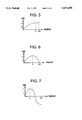
- FIGS. 5, 6, and 7 are frequency response curves of the one-delay, two-delay, and three-delay delay-subtracter dc blockers shown in FIGS. 2, 3, and 4, respectively.
- FIG. 8 is a schematic diagram of the Hilbert transformer used in the present invention.
- FIG. 9 is a overall schematic drawing of the preferred embodiment of the present invention.
- FIG. 10 is a flowchart illustrating the operation of the present invention.
- FIG. 1 is an overall schematic diagram of the present invention 10.
- An analog sinusoidal input signal 12 is applied to an analog-to-digital converter 14 which produces a digitized input signal 16.
- the digitized input signal 16 is applied to a gain-normalized dc blocker 18, the output 20 of which is applied to a Hilbert transformer 22. If desired, the dc blocker 18 may be unnormalized, as shown, with normalization taking place at any other convenient point in the signal path.
- the I and Q outputs of the Hilbert transformer 22 are separately squared in squaring elements 24, 26, and the squares 28, 30 are summed in a summer 32 to produce an output signal 34 representing the squared amplitude of the analog sinusoidal input signal 12.
- An optional square root element 36 recovers the amplitude 38 of the analog sinusoidal input signal 12.
- FIG. 2, 3, and 4 show the preferred dc blockers 18A, 18B, and 18C, namely, delay-subtracter dc blockers.
- the delay-subtracter dc blockers 18A, 18B, and 18C have one, two, and three delay elements 40A, 40B, and 40C, respectively.
- DC blockers having more than four delays should not be used, since they require an excessively large number of samples to generate the output signal.
- the output of the last delay element is applied to a subtracter 42A, 42B, or 42C which subtracts it from the digitized input signal to produce the dc blocker output 20.
- FIGS. 5, 6, and 7 show the frequency response curves for one-, two-, and three-delay dc blockers, respectively.
- the curves are sinusoids covering one, two, or three quadrants, respectively, and have a maximum gain of two.
- the actual gain will depend on where the input frequency fi actually falls. If the actual gain is not unity, it must either be allowed for or compensated for by other apparatus, forming no part of the present invention.
- a one-delay blocker (FIG. 2) should be used when the sampling frequency fs is slightly more than twice the frequency of the input signal fi (or, equivalently, when the frequency of the input signal fi is slightly less than half that of the sampling frequency fs).
- a two-delay blocker (FIGS. 3, 6) should be used when the sampling frequency is about four times the frequency of the input signal, fi (or, equivalently, when the frequency of the input signal fi is about one-fourth the sampling frequency fs)
- a three-delay blocker (FIGS.
- sampling frequency fs should be used when the sampling frequency fs is about six times the frequency of the input signal fi (or, equivalently, when the frequency of the input signal fi is about a sixth the sampling frequency fs).
- the analog-to-digital converter 14 should therefore have a sampling frequency fs of more than twice the frequency of the analog sinusoidal input signal fi (FIG. 5), but less than eight times the frequency of the analog sinusoidal input signal (FIG. 7).
- the dc-blocked signal 20 is applied to a two-delay Hilbert transformer 22, the details of which are shown in FIG. 8.
- the two-delay Hilbert transformer 22 is constructed to produce an in-phase signal I and a quadrature-phase signal Q.
- the Hilbert transformer 22 has a first delay element 44 connected to receive the dc-blocked signal 20; it produces the in-phase signal I.
- the in-phase signal I is applied to a second delay element 46, which produces a doubly delayed signal 48.
- the dc-blocked signal 20 and the doubly delayed signal 48 are applied to a subtracter 50 which produces a difference signal 52.
- the difference signal 52 is applied to a multiplier 54 constructed to multiply the difference signal 52 by a constant.
- the output of the multiplier 54 is the quadrature-phase signal Q.
- the constant represents half the cosecant of the product of the sampling period T and the radian frequency of the analog sinusoidal input signal, 2 ⁇ fi.
- FIG. 9 shows the preferred embodiment of the present invention.
- a sinusoidal analog input signal 12 of known frequency fi is sampled and digitized by an ADC 14 at about four times the frequency of the input signal fi.
- the digitized signal 16 is applied to a two-delay delay-subtracter dc blocker 18B, the output 20 of which is applied to a two-delay Hilbert transformer 22.
- Applying first, second, and third samples 16 to the dc blocker 18B allows the dc blocker 18B to produce its first output 20 to the Hilbert transformer 22.
- a fourth sample 16 applied to the dc blocker 18B causes a second output 20 to the Hilbert transformer 22, thus producing a first output from the first delay element 44 of the Hilbert transformer 22, that is, a first in-phase output I.
- a fifth sample 16 applied to the dc blocker 18B causes a third output 20 to the Hilbert transformer 22, a second in-phase output I, and a first output 48 from the second delay element 46 of the Hilbert transformer 22.
- This first output 48 from the second delay element 46 of the Hilbert transformer 22 is combined with the first output 20 to the Hilbert transformer 22 to provide the quadrature-phase output Q. This takes place in the subtracter 50 and multiplier 54.
- the in-phase I and quadrature-phase Q outputs may then be squared 24, 26 and summed 32.
- FIGS. 2 and 5 should be used. The reduces the required number of samples 16 even further, to four, but runs the risk that, if the input frequency fi drifts upward, it may drift to, or even above, the Nyquist frequency. This causes many difficulties, as is known in the art.
- FIGS. 4 and 7 should be used. This is not preferred, since the pass band is both narrower and not as flat. More importantly, six samples 16 are required before the amplitude can be measured. This taxes the limited capacities of the ADC 14 and processor.
- FIG. 10 is a flowchart 56 illustrating the operation of the present invention.
- step 58 an analog sinusoidal input signal is digitized at a sampling frequency more than twice the frequency of the analog sinusoidal input signal, but less than eight times the frequency of the analog sinusoidal input signal, thereby producing a digitized input signal.
- step 60 the digitized input signal is delay-subtract dc-blocked by delaying the signal for fewer than four delays and subtracting it from the digitized input signal, thereby producing a dc-blocked signal. There thus may be one delay, step 62, two delays, step 64, or three delays, step 66.
- the dc-blocked signal is two-delay Hilbert transformed, step 68, thereby producing an in-phase signal and a quadrature-phase signal.
- the in-phase signal is squared, step 70, thereby producing a first squared signal.
- the quadrature-phase signal is also squared, step 72, thereby producing a second squared signal.
- the first and second squared signals are summed, step 74, thereby producing a sum signal. If desired, the square root of the sum signal may be taken, step 76.
- the dc-blocker 18 (or, equivalently, the dc blocking step 60) may be omitted, and only three consecutive samples will be required. This is also an astonishingly low number, considering that a dc-free sinusoid of known frequency has two unknowns: amplitude and phase. Measuring both of these unknowns--or either of them--therefore requires the same number of consecutive samples: two.
Abstract
Description
______________________________________
U.S.
Pat. No.
       Title                    Issue Date
______________________________________
5,179,380
       One-Bit Sigma-Delta Modulator with Improved
                                01/12/93
       Signal Stability
5,339,263
       Decimator/Interpolator Filter for ADC and DAC
                                08/16/94
5,361,036
       Complex Digital Demodulator Employing
                                11/01/94
       Chebychev-Approximation Derived Synthetic-
       Sinusoid Generator
5,400,269
       Closed-Loop Baseband Controller for a
                                03/21/95
       Rebalance Loop of a Quartz Angular-Rate
       Sensor
5,444,639
       Angular-Rate-Sensing System and Method with
                                08/22/95
       Digital Synthesizer and Variable-Frequency
       Oscillator
5,444,641
       Admittance-Parameter Estimator for a
                                08/22/95
       Piezoelectric Resonator in an Oscillator Circuit
5,459,432
       Use of a Chopper and a Sigma-Delta Modulator
                                10/17/95
       for Downconverting and Digitizing an Angalog
       Signal Including Information Modulated by a
       Carrier
5,463,575
       Reduced Quantization Noise from a Single-
                                10/31/95
       Precision Multiplier
5,471,396
       Estimator of Amplitude and Frequence of a
                                11/28/95
       Noisy Biased Sinusoid from a Short Burst of
       Samples
5,487,015
       Self-Oscillating Driver circuit for a Quartz
                                01/23/96
       Resonator of an Angular-Rate Sensor
5,491,725
       A Tracking Filter and Quadrature-phase-
                                02/13/96
       Reference Generator
5,577,073
       A Frequency and Phase-Locked Two-Phase
                                11/19/96
       Digital Synthesizer
5,576,976
       Amplitude Detection and Automatic Gain
                                11/19/96
       Control of a Sparesly Sampled Sinusoid by
       Adjustment of a Notch-Filter
5,550,866
       A Demodulator/Reference Generator Based on
                                07/27/96
       Two Cascaded Hilbert Transformers
5,566,093
       Sensor with Resonator, Digital Filter, and
                                10/15/96
       Display
______________________________________
Claims (8)
Priority Applications (1)
| Application Number | Priority Date | Filing Date | Title |
|---|---|---|---|
| US08/636,088 US5675498A (en) | 1996-04-22 | 1996-04-22 | Measuring amplitude of sparsely sampled sinusoidal signal |
Applications Claiming Priority (1)
| Application Number | Priority Date | Filing Date | Title |
|---|---|---|---|
| US08/636,088 US5675498A (en) | 1996-04-22 | 1996-04-22 | Measuring amplitude of sparsely sampled sinusoidal signal |
Publications (1)
| Publication Number | Publication Date |
|---|---|
| US5675498A true US5675498A (en) | 1997-10-07 |
Family
ID=24550380
Family Applications (1)
| Application Number | Title | Priority Date | Filing Date |
|---|---|---|---|
| US08/636,088 Expired - Fee Related US5675498A (en) | 1996-04-22 | 1996-04-22 | Measuring amplitude of sparsely sampled sinusoidal signal |
Country Status (1)
| Country | Link |
|---|---|
| US (1) | US5675498A (en) |
Cited By (14)
| Publication number | Priority date | Publication date | Assignee | Title |
|---|---|---|---|---|
| US6061388A (en) * | 1996-06-07 | 2000-05-09 | General Electric Company | Spread spectrum communication system with frequency-separated message and reference signals |
| US6072997A (en) * | 1997-04-18 | 2000-06-06 | General Research Of Electronics, Inc. | Frequency discriminator for a direct conversion receiver |
| US6097884A (en) * | 1997-12-08 | 2000-08-01 | Lsi Logic Corporation | Probe points and markers for critical paths and integrated circuits |
| US6229847B1 (en) * | 1997-12-24 | 2001-05-08 | The United States Of America As Represented By The Secretary Of The Navy | Signal quality measurement device |
| EP1164355A2 (en) | 2000-06-15 | 2001-12-19 | Murata Manufacturing Co., Ltd. | Angular velocity sensor |
| DE10055375A1 (en) * | 2000-11-08 | 2002-05-23 | Infineon Technologies Ag | Evaluation circuit for alternating voltage pulses detects alternating voltage pulse using sampled values from analogue to digital converter unit multiplied by mixing frequency |
| US6400778B1 (en) * | 1997-12-04 | 2002-06-04 | Nec Corporation | DC-offset canceller |
| US6564636B2 (en) | 2001-08-22 | 2003-05-20 | Honeywell International Inc. | Wide band digital phase locked loop (PLL) with a half-frequency output |
| US6725169B2 (en) | 2002-03-07 | 2004-04-20 | Honeywell International Inc. | Methods and apparatus for automatic gain control |
| US6904443B2 (en) | 2001-08-13 | 2005-06-07 | Honeywell International Inc. | Harmonic-series filter |
| WO2007088499A2 (en) * | 2006-02-01 | 2007-08-09 | Csir | Method of instantaneously determining or estimating the frequency or amplitude of an input signal |
| CN104251932A (en) * | 2014-08-15 | 2014-12-31 | 中国计量科学研究院 | Method and system for measuring sinusoidal voltage signals |
| CN105738696A (en) * | 2016-04-18 | 2016-07-06 | 天津大学 | Frequency estimation method and device for all-phase time-shift phase difference |
| CN105929239A (en) * | 2016-05-02 | 2016-09-07 | 东北电力大学 | Quantitative determination and qualitative identification method of passive element parameters in non-sine AC circuit |
Citations (1)
| Publication number | Priority date | Publication date | Assignee | Title |
|---|---|---|---|---|
| US4495643A (en) * | 1983-03-31 | 1985-01-22 | Orban Associates, Inc. | Audio peak limiter using Hilbert transforms |
-
1996
- 1996-04-22 US US08/636,088 patent/US5675498A/en not_active Expired - Fee Related
Patent Citations (1)
| Publication number | Priority date | Publication date | Assignee | Title |
|---|---|---|---|---|
| US4495643A (en) * | 1983-03-31 | 1985-01-22 | Orban Associates, Inc. | Audio peak limiter using Hilbert transforms |
Cited By (24)
| Publication number | Priority date | Publication date | Assignee | Title |
|---|---|---|---|---|
| US6061388A (en) * | 1996-06-07 | 2000-05-09 | General Electric Company | Spread spectrum communication system with frequency-separated message and reference signals |
| US6072997A (en) * | 1997-04-18 | 2000-06-06 | General Research Of Electronics, Inc. | Frequency discriminator for a direct conversion receiver |
| US6400778B1 (en) * | 1997-12-04 | 2002-06-04 | Nec Corporation | DC-offset canceller |
| US6097884A (en) * | 1997-12-08 | 2000-08-01 | Lsi Logic Corporation | Probe points and markers for critical paths and integrated circuits |
| US6229847B1 (en) * | 1997-12-24 | 2001-05-08 | The United States Of America As Represented By The Secretary Of The Navy | Signal quality measurement device |
| EP1164355A3 (en) * | 2000-06-15 | 2004-12-15 | Murata Manufacturing Co., Ltd. | Angular velocity sensor |
| EP1164355A2 (en) | 2000-06-15 | 2001-12-19 | Murata Manufacturing Co., Ltd. | Angular velocity sensor |
| US7085373B2 (en) | 2000-11-08 | 2006-08-01 | Infineon Technologies Ag | Circuit and method for detecting AC voltage pulses |
| US20030207677A1 (en) * | 2000-11-08 | 2003-11-06 | Thomas Hauser | Circuit and method for detecting AC voltage pulses |
| DE10055375A1 (en) * | 2000-11-08 | 2002-05-23 | Infineon Technologies Ag | Evaluation circuit for alternating voltage pulses detects alternating voltage pulse using sampled values from analogue to digital converter unit multiplied by mixing frequency |
| US20060210055A1 (en) * | 2000-11-08 | 2006-09-21 | Thomas Hauser | Circuit and method for detecting ac voltage pulses |
| CN1526230B (en) * | 2000-11-08 | 2011-06-15 | 因芬尼昂技术股份公司 | Evaluation circuit for alternating voltage pulses,method and telephone equipped therewith |
| US6904443B2 (en) | 2001-08-13 | 2005-06-07 | Honeywell International Inc. | Harmonic-series filter |
| US6564636B2 (en) | 2001-08-22 | 2003-05-20 | Honeywell International Inc. | Wide band digital phase locked loop (PLL) with a half-frequency output |
| US6725169B2 (en) | 2002-03-07 | 2004-04-20 | Honeywell International Inc. | Methods and apparatus for automatic gain control |
| US20090237070A1 (en) * | 2006-02-01 | 2009-09-24 | Paul Le Roux Herselman | Method of instantaneously determining or estimating the frequency or amplitude of an input signal |
| WO2007088499A3 (en) * | 2006-02-01 | 2007-12-13 | Csir | Method of instantaneously determining or estimating the frequency or amplitude of an input signal |
| WO2007088499A2 (en) * | 2006-02-01 | 2007-08-09 | Csir | Method of instantaneously determining or estimating the frequency or amplitude of an input signal |
| CN104251932A (en) * | 2014-08-15 | 2014-12-31 | 中国计量科学研究院 | Method and system for measuring sinusoidal voltage signals |
| CN104251932B (en) * | 2014-08-15 | 2017-02-15 | 中国计量科学研究院 | Method and system for measuring sinusoidal voltage signals |
| CN105738696A (en) * | 2016-04-18 | 2016-07-06 | 天津大学 | Frequency estimation method and device for all-phase time-shift phase difference |
| CN105738696B (en) * | 2016-04-18 | 2019-03-05 | 天津大学 | Full phase time shift phase difference frequency estimating methods and device |
| CN105929239A (en) * | 2016-05-02 | 2016-09-07 | 东北电力大学 | Quantitative determination and qualitative identification method of passive element parameters in non-sine AC circuit |
| CN105929239B (en) * | 2016-05-02 | 2018-09-07 | 东北电力大学 | The quantitative detection of passive element parameter and qualitative recognition method in a kind of Non-sinusodal AC circuit |
Similar Documents
| Publication | Publication Date | Title |
|---|---|---|
| US5675498A (en) | Measuring amplitude of sparsely sampled sinusoidal signal | |
| US5001724A (en) | Method and apparatus for measuring phase accuracy and amplitude profile of a continuous-phase-modulated signal | |
| US4464770A (en) | Synchronous radio or television receiver with analog high frequency section followed by digital low frequency section | |
| US5052050A (en) | Direct conversion FM receiver | |
| US5459432A (en) | Use of a chopper and a sigma-delta modulator for downconverting and digitizing an analog signal including information modulated by a carrier | |
| KR100444805B1 (en) | A digital control system for a vibrating structure gyroscope | |
| JP4360739B2 (en) | Quadrature demodulation apparatus, method, and recording medium | |
| EP0106029B1 (en) | Method and apparatus for measuring the amplitude of a noise-affected periodic signal without phase reference | |
| JP2976706B2 (en) | Frequency conversion type coherent A / D conversion system for modulated signal | |
| US5548244A (en) | Method and apparatus for eliminating DC offset for digital I/Q demodulators | |
| GB2233518A (en) | Analogue to digital converters | |
| JPH1023086A (en) | Instrument for measuring modulation precision | |
| JPH04252503A (en) | Fm demodulator | |
| JPS6195602A (en) | Frequency information detector | |
| EP0310960A3 (en) | Digital lock-in amplifier | |
| GB2234411A (en) | Integrated circuit for digital demodulation | |
| JPH0620197B2 (en) | Variable speed clock recovery circuit | |
| EP0259867A2 (en) | Demodulator for psk-modulated signals | |
| US6982538B2 (en) | Methods and apparatus for generating a sinusoidal motor drive signal for a MEMS gyroscope | |
| JPS60203045A (en) | Phase locking detection demodulator | |
| US5764705A (en) | Adaptive phase shift adjuster for resonator | |
| US5732003A (en) | Sawtooth phase filter | |
| JP2504243B2 (en) | Demodulation method | |
| US4864221A (en) | Filter, phase-measuring device and method for application of said filter | |
| KR950010625A (en) | HDTV receiver |
Legal Events
| Date | Code | Title | Description |
|---|---|---|---|
| AS | Assignment |
Owner name: ROCKWELL INTERNATIONAL CORPORATION, CALIFORNIA Free format text: ASSIGNMENT OF ASSIGNORS INTEREST;ASSIGNOR:WHITE, STANLEY A.;REEL/FRAME:008018/0272 Effective date: 19960404 |
|
| AS | Assignment |
Owner name: BOEING NORTH AMERICAN, INC., CALIFORNIA Free format text: MERGER;ASSIGNOR:ROCKWELL INTERNATIONAL CORPORATION;REEL/FRAME:008547/0326 Effective date: 19961206 |
|
| FEPP | Fee payment procedure |
Free format text: PAYOR NUMBER ASSIGNED (ORIGINAL EVENT CODE: ASPN); ENTITY STATUS OF PATENT OWNER: LARGE ENTITY |
|
| FPAY | Fee payment |
Year of fee payment: 4 |
|
| AS | Assignment |
Owner name: BEI TECHNOLOGIES, INC., CALIFORNIA Free format text: ASSIGNMENT OF ASSIGNORS INTEREST;ASSIGNOR:BOEING COMPANY, THE;REEL/FRAME:014797/0375 Effective date: 20030822 Owner name: BOEING COMPANY, THE, ILLINOIS Free format text: MERGER;ASSIGNOR:BOEING NORTH AMERICAN, INC.;REEL/FRAME:014797/0363 Effective date: 19991230 |
|
| FEPP | Fee payment procedure |
Free format text: PAYOR NUMBER ASSIGNED (ORIGINAL EVENT CODE: ASPN); ENTITY STATUS OF PATENT OWNER: LARGE ENTITY Free format text: PAYER NUMBER DE-ASSIGNED (ORIGINAL EVENT CODE: RMPN); ENTITY STATUS OF PATENT OWNER: LARGE ENTITY |
|
| FPAY | Fee payment |
Year of fee payment: 8 |
|
| REMI | Maintenance fee reminder mailed | ||
| LAPS | Lapse for failure to pay maintenance fees | ||
| STCH | Information on status: patent discontinuation |
Free format text: PATENT EXPIRED DUE TO NONPAYMENT OF MAINTENANCE FEES UNDER 37 CFR 1.362 |
|
| FP | Lapsed due to failure to pay maintenance fee |
Effective date: 20091007 |