US5656193A - Pilaster form - Google Patents
Pilaster form Download PDFInfo
- Publication number
- US5656193A US5656193A US08/384,788 US38478895A US5656193A US 5656193 A US5656193 A US 5656193A US 38478895 A US38478895 A US 38478895A US 5656193 A US5656193 A US 5656193A
- Authority
- US
- United States
- Prior art keywords
- pilaster
- forming
- filler
- wall
- forming surface
- Prior art date
- Legal status (The legal status is an assumption and is not a legal conclusion. Google has not performed a legal analysis and makes no representation as to the accuracy of the status listed.)
- Expired - Lifetime
Links
Images


Classifications
-
- E—FIXED CONSTRUCTIONS
- E04—BUILDING
- E04G—SCAFFOLDING; FORMS; SHUTTERING; BUILDING IMPLEMENTS OR AIDS, OR THEIR USE; HANDLING BUILDING MATERIALS ON THE SITE; REPAIRING, BREAKING-UP OR OTHER WORK ON EXISTING BUILDINGS
- E04G13/00—Falsework, forms, or shutterings for particular parts of buildings, e.g. stairs, steps, cornices, balconies foundations, sills
- E04G13/02—Falsework, forms, or shutterings for particular parts of buildings, e.g. stairs, steps, cornices, balconies foundations, sills for columns or like pillars; Special tying or clamping means therefor
- E04G13/023—Falsework, forms, or shutterings for particular parts of buildings, e.g. stairs, steps, cornices, balconies foundations, sills for columns or like pillars; Special tying or clamping means therefor with means for modifying the sectional dimensions
-
- E—FIXED CONSTRUCTIONS
- E04—BUILDING
- E04G—SCAFFOLDING; FORMS; SHUTTERING; BUILDING IMPLEMENTS OR AIDS, OR THEIR USE; HANDLING BUILDING MATERIALS ON THE SITE; REPAIRING, BREAKING-UP OR OTHER WORK ON EXISTING BUILDINGS
- E04G13/00—Falsework, forms, or shutterings for particular parts of buildings, e.g. stairs, steps, cornices, balconies foundations, sills
- E04G13/04—Falsework, forms, or shutterings for particular parts of buildings, e.g. stairs, steps, cornices, balconies foundations, sills for lintels, beams, or transoms to be encased separately; Special tying or clamping means therefor
-
- E—FIXED CONSTRUCTIONS
- E04—BUILDING
- E04G—SCAFFOLDING; FORMS; SHUTTERING; BUILDING IMPLEMENTS OR AIDS, OR THEIR USE; HANDLING BUILDING MATERIALS ON THE SITE; REPAIRING, BREAKING-UP OR OTHER WORK ON EXISTING BUILDINGS
- E04G17/00—Connecting or other auxiliary members for forms, falsework structures, or shutterings
- E04G17/14—Bracing or strutting arrangements for formwalls; Devices for aligning forms
Definitions
- the present invention is generally directed to the field of accessories and components for concrete forms and the like and, more particularly, a pilaster form for use in forming a pilaster for a concrete wall in any of a plurality of widths and depths.
- the panels In wall forming systems, it is typical for the panels to be designed in such manner as to be vertically positioned.
- the panels and fillers are conventionally available in a variety of heights and backing bar configurations for specific applications.
- workmen utilize such wall forming systems, there are oftentimes still additional important requirements.
- a concrete wall is formed so as to have one or more pilasters.
- each form typically has attached hardware that secures the ties and subsequent form. This connection also helps to align the formwork. Further, water brackets typically slide over hex headbolts and accept standard lumber to bring formwork into final alignment.
- the present invention is directed to overcoming one or more of the foregoing problems and achieving one or more of the resulting objects.
- the first side unit of the pilaster form is adapted for interconnection with a first section of a wall form to form a first side of a pilaster and there are means integral with either the first side unit or the first; section of the wall form for releasably securing the first side unit to the first section of the wall form.
- the second side unit of the pilaster form is adapted for interconnection with a second section of the wall form to form a second side of the pilaster and there are means integral with either the second side unit or the second section of the wall form for releasably securing the second side unit to the second section of the wall form.
- the filler of the pilaster form is adapted for interconnection with the first and second side units of the pilaster form to form an outwardly facing surface of the pilaster and there are means integral with at least either the first and second side units or the filler for releasably securing the filler to the first and second side units of the pilaster form.
- the filler releasable securing means is operable to releasably secure the filler at any one of a plurality of positions in relation to the wall form.
- the positions at which the filler can be releasably secured in relation to the wall form are such as to permit the forming of the pilaster in a plurality of depths in relation to the concrete wall.
- the first and second side units each have a face for forming the sides of the pilaster together with first and second edges extending along opposite sides of the corresponding one of the faces.
- the side unit releasable securing means each advantageously includes a mounting block integral with the corresponding one of the side units with each of the mounting blocks having an integral latch bolt for receiving or carrying a latch.
- the side unit releasable securing means each preferably includes at least a latch integral with one and a latch bolt integral with the other of the corresponding ones of the side units and wall form sections.
- the filler also advantageously has a face for forming the outwardly facing surface of the pilaster together with first and second edges extending along opposite sides thereof.
- the filler releasable securing means preferably includes at least a latch integral with one and a latch bolt integral with the other of the corresponding ones of the side units and the filler.
- the face of each of the first and second side units is generally planar and the first and second edges extending along opposite sides of the corresponding one of the faces are generally parallel.
- the face of the filler for forming the outwardly facing surface of the pilaster is preferably generally planar and the first and second edges extending along opposite sides of the face of the filler are preferably generally parallel.
- each of the first and second side units advantageously has a return bend integral with one of the first and second generally parallel edges to provide a wall forming flange and a wall form abutting flange. It is also preferred for each of the sections of the wall form to have a generally planar face for forming the concrete wall and, further, for each of the sections of the wall form to also have a side edge for abutment by one of the wall form abutting flanges. With this construction, each of the wall forming flanges advantageously has a generally planar face to be secured generally coplanar with the generally planar face of the section of the wall form against which it is abutted for forming the concrete wall.
- each of the wall form abutting flanges has a generally planar surface to be secured in abutment with the side edge of one of the sections of the wall form for forming the concrete wall.
- each of the side unit releasable securing means includes a plurality of vertically spaced mounting blocks integral with the corresponding one of the side units and each of the vertically spaced mounting blocks has an integral latch bolt for receiving or carrying a latch.
- the filler releasable securing means advantageously includes at least a plurality of latches integral with one and a plurality of latch bolts integral with the other of the corresponding ones of the side units and the filler.
- each of the side unit releasable securing means most advantageously includes a plurality of vertically spaced latch bolts which are integral with the corresponding one of the sections of the wall form with each of the latch bolts being provided so as to receive or carry a latch.
- the filler releasable securing means includes a plurality of angles vertically secured in parallel horizontally spaced relation on an outer surface of each of the first and second side units with each of the angles carrying a selected number of the latch bolts and each of the latch bolts being adapted to receive and/or carry a latch for interconnection with the filler.
- the latch bolts preferably each extend generally perpendicular to a flange of the angle so as to extend in a direction generally parallel to the outer surface of the respective one of the first and second side units with the latch bolts each threadingly engaging the flange of the respective ones of the angles for threaded movement toward and away from the respective ones of the flanges.
- a plurality of the latches are integrally associated with one of the edges of the filler and a plurality of latch bolts are integral with the other of the edges of the filler such that the latch bolts integrally associated with the angles of one of the side units is adapted to receive a corresponding one of the latches integrally associated with the one of the edges of the filler.
- the pilaster form advantageously includes a plurality of latch clips each of which is adapted to be interconnected to one of the latch bolts integral with the other of the edges of the filler and also to be interconnected with a corresponding one of the latch bolts integral with one of the angles of the other of the side units.
- each of the latch bolts integrally associated with the angles of the other of the side units carries a latch for interconnection with the filler such that the latches are adapted to be interconnected with a corresponding one of the latch bolts integral with the filler.
- the filler releasable securing means advantageously further includes a plurality of vertically extending rows of apertures in each of the first and second side units.
- the pilaster form may include mask means for preventing leakage of concrete through exposed and unused ones of the vertically extending apertures during a concrete pouring operation.
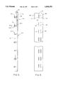
- FIG. 1 is a top plan view of a pilaster form in accordance with the present invention.
- FIG. 1A is a perspective view of a concrete wall formed with the pilaster form of FIG. 1;
- FIG. 2 is a cross-sectional view taken generally along the line 2--2 of FIG. 1;
- FIG. 3 is a front elevational view of a side unit of the pilaster form of FIG. 1;
- FIG. 4 is a top plan view taken generally along the line 4--4 of FIG. 3;
- FIG. 5 is a side elevational view of a side unit of the pilaster form of FIG. 1.
- the reference numeral 10 designates generally a pilaster form which is particularly suited for use in forming a pilaster such as 12 for a concrete wall such as 14.
- the pilaster form 10 includes a first side unit 16 for interconnection with a first section 18 of a wall form 20 to form a first side 22 of the pilaster 12, a second side unit 24 for interconnection with a second section 26 of the wall form 20 to form a second side 28 of the pilaster 12, and a filler 30 for interconnection with the first and second side units 16 and 24 of the pilaster form 10 to form an outwardly facing surface 32 of the pilaster 12 (FIGS. 1 and 1A).
- first and second side units 16 and 24 each have a generally planar face 34 and 36 for forming the sides 22 and 28 of the pilaster 12 and the filler 30 has a generally planar face 38 for forming the outwardly facing surface 32 of the pilaster 12.
- the first and second side units 16 and 24 each also have first and second generally parallel edges 42, 44 and 46, 48, respectively, extending along opposite sides of the corresponding ones of the faces 34 and 36.
- each of the first and second side units 16 and 24 has a return bend 50 and 52, respectively, integral with one of the first and second generally parallel edges to provide a wall forming flange 50a and 52a, respectively, and a wall form abutting flange 50b and 52b, respectively.
- each of the return bends 50 and 52 will be seen to be integral with the edges 44 and 48, respectively, which are opposite the edges 42 and 46, respectively, as perhaps best shown in FIG. 1.
- the pilaster form 10 includes means integral with either the first side unit 16 or the first section 18 of the wall form 20 for releasably securing the first side unit 16 to the first section 18 of the wall form 20.
- the pilaster form 10 includes means integral with either the second side unit 24 or the second section 26 of the wall form 20 for releasably securing the second side unit 24 to the second section 26 of the wall form 20.
- each of the side unit releasable securing means includes a plurality of vertically spaced mounting blocks 54 and 56 integral with the corresponding one of the side units 16 and 24, respectively. It will also be appreciated that each of the vertically spaced mounting blocks 54 and 56 has an integral latch bolt 58 and 60, respectively. As will best be appreciated from FIG. 1, the latch bolts 58 and 60 which are integral with the corresponding vertically spaced mounting blocks 58 and 60 are well adapted for either carrying a latch 62 or receiving a latch 64 substantially as shown.
- each of the side unit releasable securing means further includes a latch bolt 66 and 68 which is integral with the corresponding one of the sections 18 and 26 of the wall form 20.
- latch bolt 66 and 68 which is integral with the corresponding one of the sections 18 and 26 of the wall form 20.
- latch bolts 66 and 68 there will be a plurality of vertically spaced latch bolts 66 and 68 which are generally in proximity to respective edges of the sections 18 and 26 of the wall form 20.
- the latch bolts 66 each receive one of the latches 62 carried by the latch bolt 58 and the latch bolts 68 each carry one of the latches 64 to be received by one of the latch bolts 60.
- each of the sections 18 and 26 will be understood to have a generally planar face 70 and 72, respectively, which is well suited for forming the concrete wall 14. It will also be appreciated that each of the sections 18 and 26 of the wall form 20 have a side edge 74 and 76, respectively, for abutment by one of the wall form abutting flanges 50b and 52b, respectively. It will further be appreciated that each of the wall form abutting flanges 50b and 52b has a generally planar surface to be secured in abutment with the side edges 74 and 76, respectively, of the sections 18 and 26, respectively. With this particular arrangement, the wall forming flanges 50a and 52a will also be understood as having a generally planar face to be secured generally coplanar with the corresponding generally planar faces 70 and 72 of the sections 18 and 26 of the wall form 20.
- the mounting blocks 54 and 56 are nested in the vertically extending spaces 78 and 80, respectively, defined by the return bends 50 and 52, respectively, in relation to the remainder of the side units 16 and 24, respectively.
- the filler 30 has a generally planar face 38 for forming the outwardly facing surface 32 of the pilaster 12 and it also has first and second generally parallel edges 82 and 84 extending along opposite sides thereof.
- the pilaster form 10 includes means integral with at least one of the first and second side unit 16 and 24 and filler 30 for releasably securing the filler 30 to the first and second side units 16 and 24 of the pilaster form 10.
- the filler releasable securing means will be understood as being operable to releasably secure the filler 30 at any one of a plurality of distinct positions in relation to the wall form 20.
- the positions at which the filler is releasably secured are advantageously such as to permit the forming of the pilaster 12 in any of a plurality of different depths in relation to the concrete wall 14.
- the filler releasable securing means preferably includes at least a plurality of latches such as 86 which are integral with one and a plurality of latch bolts such as 88 which are integral with the other of the corresponding ones of the side units 16 and 24 and the filler 30.
- the filler releasable securing means includes a plurality of angles 90, 92, 94 and 96, 98, 100 vertically secured in parallel horizontally spaced relation on an outer surface 102 and 104, respectively, of each of the first and second side units 16 and 24, respectively.
- each of the angles 90, 92, 94 and 96, 98, 100 carry a selected number of the latch bolts such as 88 and each of the latch bolts such as 88 is adapted to receive and/or carry a latch for interconnection with the filler 30.
- the latch bolts such as 88 each extend generally perpendicular to a flange such as 92a of the corresponding one of the angles such as 92 so as to extend in a direction which is generally parallel to the outer surface such as 102 of the respective one of the first and second side units such as 16.
- the latch bolts such as 88 each threadingly engage the flange such as 92a of the respective one of the angles such as 92 for threaded movement toward and away from the flange such as 92 to capture a latch such as 86 therebetween.
- the pilaster form 10 includes a plurality of the latches 86 which are preferably integrally associated with one of the edges 82 of the filler 30 and a plurality of latch bolts 106 adjacent the other of the edges 84.
- the latch bolts such as 88 integrally associated with the angles such as 92 of one of the side units such as 16 are adapted to receive a corresponding one of the plurality of latches 86 integrally associated with the one of the edges 82 of the filler 30 as by a latch bolt 108.
- the pilaster form 10 utilizes a plurality of latch clips 110 each of which is adapted to be interconnected to one of the plurality of latch bolts 106 integral with the filler 30 adjacent the other of the edges 84.
- the latch bolts such as 112 integral with one of the angles such as 98 of the other of the side units such as 24 are each also adapted to receive and be interconnected with a corresponding one of the plurality of latch clips 110.
- the latch bolts such as 112 integrally associated with the angles such as 98 of the other of the side units such as 24 each carry a latch (not shown) which is essentially identical to the latch 86.
- This latch can be interconnected with the filler in much the same way that the latch 86 integral with the filler 30 is interconnected with the one of the side units 16. More specifically, the latches carded by the latch bolts such as 112 associated with the other of the side units such as 24 each can be interconnected with a corresponding one of the latch bolts such as 106 integral with the filler 30.
- latches such as 86 and the latch clips such as 110 they are not specifically shown in detail in the drawings. It will be appreciated, however, that the latches such as 62 are clearly shown in FIG. 3 and, moreover, the latches such as 86 can be similarly configured, as can the latch clips 110 although the latches 62 are different in one respect, i.e., they each include one slot such as 62a to fit over the shank 66a and behind the head 66b of the latch bolt 66 and they also include another slot such as 62b into which a tie (which is schematically illustrated at 114 in FIG. 1) can be secured.
- the latches 86 need only have a single slot such as 62a to be secured over the shank 88a and behind the head 88b of the latch bolt 88.
- latches 62 and 86 may each be formed so as to have a hole such as 62c for the purpose of receiving a latch bolt such as 58 as shown in FIG. 3.
- the latch clip 110 will differ in that it will simply have a slot such as 62a in latch 62 to cooperate with the latch bolt 106 and it will also have another essentially identical slot at the end of the latch clip 110 opposite the first-mentioned slot to cooperate with the latch bolt 112.
- the parallel slots in the latch clip 110 can be inserted over the shanks 106a and 112a and behind the heads 106b and 112b of the latch bolts 106 and 112, respectively.
- the filler releasable securing means will be seen to further include a plurality of vertically extending rows of apertures such as 116 and 118 in each of the first and second side units 16 and 24. It will be appreciated that each of these apertures is generally adjacent one of the latch bolts integrally associated with the angles 90, 92 and 96, 98 and they are vertically sized to accommodate pivotally extending one of the latches such as 86 (or a latch clip 110) through the respective one of the apertures for interconnection of the respective one of the side units 16 and 24 and the filler 30 as described above. Still further, the pilaster form 10 may include mask means in the form of thin flat vertical sheets 120 and 122 to prevent leakage of concrete through exposed and unused ones of the vertically extending apertures 116 and 118 during a concrete pouting operation.
- the first and second side units 16 and 24 may include suitable reinforcing at the top and bottom thereof.
- the first side unit 16 (which has been illustrated) includes a diagonal brace 124 which suitably extends from the wall form abutting flange 50b to the outer surface 102 at a diagonally spaced point. With this arrangement, the diagonal braces 124 at the top and bottom of the first side unit 16 provide stiffness to prevent twisting thereof.
- the pilaster 12 may be formed of any desired width by using one or more standard concrete forming fillers such as 30 which come in a variety of different widths.
- standard fillers such as 30 which come in a variety of different widths.
- more than one such standard filler can be utilized in a known manner depending upon the width which is desired for the pilaster 12.
- the pilaster form 10 permits the pilaster 12 to be formed in a plurality of depths due to the vertically extending rows of apertures or slots 116 and 118 in the faces 34 and 36 of the side units 16 and 24 in conjunction with the securing angles 90, 92, 94 and 96, 98, 100 and latch bolts integral therewith.
- the first and second side units 16 and 24 can be formed of any suitable material such as steel, aluminum, plastic, etc.
- the mounting blocks 54 and 56 serve as a base for attaching the latch bolts 58 and 60 which, in turn, keep the latches such as 62 secured to the mounting blocks such as 54 or, alternatively, receives the latches such as 64 secured to an adjacent section such as 26 of the wall form 20.
- the latches such as 62, 64, 86, etc. swing over the next adjacent latch bolt such as 66, 60, 88, etc. to connect the sections of the form together as well as serving to capture ties such as 114.
- securing angles 90, 92, 94 and 96, 98, 100 serve to stiffen the faces 34 and 36 of the side units 16 and 24 and to also provide a mounting surface for latch bolts such as 88 and 112.
- latch bolts such as 88 and 112.
- apertures or slots 116 and 118 in the side units 16 and 24 they permit penetration of a latch such as 86 or a latch clip such as 110 to connect the filler 30 to the side units 16 and 24.
Abstract
Description
Claims (20)
Priority Applications (1)
| Application Number | Priority Date | Filing Date | Title |
|---|---|---|---|
| US08/384,788 US5656193A (en) | 1995-02-07 | 1995-02-07 | Pilaster form |
Applications Claiming Priority (1)
| Application Number | Priority Date | Filing Date | Title |
|---|---|---|---|
| US08/384,788 US5656193A (en) | 1995-02-07 | 1995-02-07 | Pilaster form |
Publications (1)
| Publication Number | Publication Date |
|---|---|
| US5656193A true US5656193A (en) | 1997-08-12 |
Family
ID=23518770
Family Applications (1)
| Application Number | Title | Priority Date | Filing Date |
|---|---|---|---|
| US08/384,788 Expired - Lifetime US5656193A (en) | 1995-02-07 | 1995-02-07 | Pilaster form |
Country Status (1)
| Country | Link |
|---|---|
| US (1) | US5656193A (en) |
Cited By (3)
| Publication number | Priority date | Publication date | Assignee | Title |
|---|---|---|---|---|
| CN104234417A (en) * | 2014-09-12 | 2014-12-24 | 北京建工集团有限责任公司 | Gear-shaped special reinforcing system for pilaster groove template |
| CN109944164A (en) * | 2019-03-13 | 2019-06-28 | 中建市政工程有限公司 | Jack up hollow thin-walled high pier roller die system and its construction method |
| US10550590B2 (en) * | 2017-01-23 | 2020-02-04 | Titcomb Brothers Manufacturing, Inc. | Concrete forming system filler bars with bolt plate assembly |
Citations (6)
| Publication number | Priority date | Publication date | Assignee | Title |
|---|---|---|---|---|
| GB216404A (en) * | 1923-08-17 | 1924-05-29 | John Thomas Mcnay | Adjustable framing or supports for centering for concrete floors, beams and the like |
| GB259037A (en) * | 1925-10-13 | 1926-10-07 | John Thomas Mcnay | Improvements in adjustable framing or supports for centering for concrete floors, beams and the like |
| US3833199A (en) * | 1972-11-15 | 1974-09-03 | A Frake | End plate for concrete forms |
| US4227672A (en) * | 1979-03-26 | 1980-10-14 | Cunningham Arthur L | Beam form and shoring structure |
| US4722541A (en) * | 1983-07-22 | 1988-02-02 | Phillips Petroleum Company | Splash and spray suppressor for vehicles |
| US5174909A (en) * | 1990-01-18 | 1992-12-29 | Western Forms, Inc. | Latching bolt mechanism and mount for concrete forming system |
-
1995
- 1995-02-07 US US08/384,788 patent/US5656193A/en not_active Expired - Lifetime
Patent Citations (6)
| Publication number | Priority date | Publication date | Assignee | Title |
|---|---|---|---|---|
| GB216404A (en) * | 1923-08-17 | 1924-05-29 | John Thomas Mcnay | Adjustable framing or supports for centering for concrete floors, beams and the like |
| GB259037A (en) * | 1925-10-13 | 1926-10-07 | John Thomas Mcnay | Improvements in adjustable framing or supports for centering for concrete floors, beams and the like |
| US3833199A (en) * | 1972-11-15 | 1974-09-03 | A Frake | End plate for concrete forms |
| US4227672A (en) * | 1979-03-26 | 1980-10-14 | Cunningham Arthur L | Beam form and shoring structure |
| US4722541A (en) * | 1983-07-22 | 1988-02-02 | Phillips Petroleum Company | Splash and spray suppressor for vehicles |
| US5174909A (en) * | 1990-01-18 | 1992-12-29 | Western Forms, Inc. | Latching bolt mechanism and mount for concrete forming system |
Non-Patent Citations (4)
| Title |
|---|
| "Pilaster Forming", Symons Corporation, Mar. 1988. |
| "Pilaster Forms", Symons Corporation, undated. |
| Pilaster Forming , Symons Corporation, Mar. 1988. * |
| Pilaster Forms , Symons Corporation, undated. * |
Cited By (4)
| Publication number | Priority date | Publication date | Assignee | Title |
|---|---|---|---|---|
| CN104234417A (en) * | 2014-09-12 | 2014-12-24 | 北京建工集团有限责任公司 | Gear-shaped special reinforcing system for pilaster groove template |
| US10550590B2 (en) * | 2017-01-23 | 2020-02-04 | Titcomb Brothers Manufacturing, Inc. | Concrete forming system filler bars with bolt plate assembly |
| CN109944164A (en) * | 2019-03-13 | 2019-06-28 | 中建市政工程有限公司 | Jack up hollow thin-walled high pier roller die system and its construction method |
| CN109944164B (en) * | 2019-03-13 | 2021-02-26 | 中建市政工程有限公司 | Self-elevating hollow thin-wall pier roller die system and construction method thereof |
Similar Documents
| Publication | Publication Date | Title |
|---|---|---|
| US6519906B2 (en) | Corner assemblies for concrete form panels | |
| US4910934A (en) | Blind construction lock and method of utilization of the lock in building construction | |
| US5078360A (en) | Prefabricated assembly for poured concrete forming structures | |
| US5890337A (en) | Double tie | |
| US6173937B1 (en) | Cap clip and spreader for poured concrete wall forms | |
| US9617744B2 (en) | Construction safety handrail support bracket | |
| US5482395A (en) | Clip connector for joining columns and beams to concrete | |
| EP1413686B1 (en) | Hip jack girder connection | |
| US8215608B2 (en) | Curved concrete radius forming system having flexible form members with attached stake holders | |
| US4791767A (en) | Wale clamp | |
| US5316253A (en) | Scaffold bracket | |
| US5656193A (en) | Pilaster form | |
| US6826880B2 (en) | Corner assemblies for concrete form panels | |
| CA1188126A (en) | Multi-panelled concrete forming structure for forming flat or curved walls | |
| US20040139672A1 (en) | System for making walls | |
| US20110232218A1 (en) | Form work, system, and method | |
| KR20200053740A (en) | Form connecting apparatus for curved wall construction | |
| US4724647A (en) | Diagonal ceiling brace | |
| JP2609971B2 (en) | Fixed frame for pier in concrete formwork panel | |
| WO2002008535A2 (en) | Multipurpose modular concrete form | |
| JPH11193572A (en) | Joint fixing for wooden building | |
| JPH0647081Y2 (en) | Formwork panel connection structure and formwork panel used for this | |
| WO2022246499A1 (en) | Formwork system & method for forming a slab with a rebate | |
| AU2022202041A1 (en) | Post bracket and blank for forming same | |
| JPH07180216A (en) | Structure of concrete building, construction method therefor and member used in the same |
Legal Events
| Date | Code | Title | Description |
|---|---|---|---|
| AS | Assignment |
Owner name: SYMONS CORPORATION Free format text: ASSIGNMENT OF ASSIGNORS INTEREST;ASSIGNORS:LOPEZ, MANUEL;MILLER, MICHAEL J.;REEL/FRAME:007397/0524 Effective date: 19950202 |
|
| STCF | Information on status: patent grant |
Free format text: PATENTED CASE |
|
| AS | Assignment |
Owner name: BANK ONE, N.A., OHIO Free format text: SECURITY AGREEMENT;ASSIGNOR:SYMONS CORPORATION;REEL/FRAME:008792/0089 Effective date: 19971029 |
|
| CC | Certificate of correction | ||
| AS | Assignment |
Owner name: BANKERS TRUST COMPANY, NEW YORK Free format text: SECURITY INTEREST;ASSIGNOR:SYMONS CORPORATION;REEL/FRAME:011019/0638 Effective date: 20000616 |
|
| FPAY | Fee payment |
Year of fee payment: 4 |
|
| AS | Assignment |
Owner name: DUR-O-WAL, INC., ILLINOIS Free format text: RELEASE OF SECURITY INTEREST;ASSIGNOR:BANK ONE, N.A.;REEL/FRAME:014901/0052 Effective date: 20031205 |
|
| AS | Assignment |
Owner name: GENERAL ELECTRIC CAPITAL CORPORATION, NEW YORK Free format text: SECURITY AGREEMENT;ASSIGNOR:SYMONS CORPORATION;REEL/FRAME:014301/0058 Effective date: 20040130 |
|
| AS | Assignment |
Owner name: BANK OF NEW YORK, THE, NEW YORK Free format text: SECURITY INTEREST AMENDMENT;ASSIGNOR:SYMONS CORPORATION;REEL/FRAME:014953/0205 Effective date: 20040130 Owner name: BANK OF NEW YORK, THE, NEW YORK Free format text: SECURITY INTEREST;ASSIGNOR:SYMONS CORPORATION;REEL/FRAME:014943/0836 Effective date: 20040130 |
|
| REMI | Maintenance fee reminder mailed | ||
| FPAY | Fee payment |
Year of fee payment: 8 |
|
| SULP | Surcharge for late payment |
Year of fee payment: 7 |
|
| AS | Assignment |
Owner name: DAYTON SUPERIOR DELAWARE CORPORATION (D/B/A DAYTON Free format text: MERGER;ASSIGNOR:DAYTON SUPERIOR CORPORATION;REEL/FRAME:018700/0913 Effective date: 20061214 |
|
| AS | Assignment |
Owner name: DAYTON SUPERIOR CORPORATION, OHIO Free format text: MERGER;ASSIGNOR:SYMONS CORPORATION;REEL/FRAME:018731/0955 Effective date: 20041013 |
|
| FEPP | Fee payment procedure |
Free format text: PAYOR NUMBER ASSIGNED (ORIGINAL EVENT CODE: ASPN); ENTITY STATUS OF PATENT OWNER: LARGE ENTITY |
|
| AS | Assignment |
Owner name: SYMONS CORPORATION, ILLINOIS Free format text: RELEASE OF SECURITY INTEREST;ASSIGNOR:BANK ONE, N.A.;REEL/FRAME:020487/0693 Effective date: 20031205 |
|
| AS | Assignment |
Owner name: DAYTON SUPERIOR CORPORATION, AS SUCCESSOR IN INTER Free format text: RELEASE OF SECURITY INTEREST AT REEL/FRAME NO. 11019/0638;ASSIGNOR:DEUTSCHE BANK TRUST COMPANY AMERICAS, FORMERLY KNOWN AS BANKERS TRUST COMPANY;REEL/FRAME:020555/0808 Effective date: 20080220 |
|
| AS | Assignment |
Owner name: DAYTON SUPERIOR CORPORATION, AS SUCCESSOR IN INTER Free format text: RELEASE OF SECURITY INTERESTS AT REEL/FRAME NOS. 14943/0836 AND 14953/0205;ASSIGNOR:THE BANK OF NEW YORK;REEL/FRAME:020593/0061 Effective date: 20080303 |
|
| AS | Assignment |
Owner name: GENERAL ELECTRIC CAPITAL CORPORATION, AS ADMINISTR Free format text: SECURITY INTEREST PURSUANT TO THE REVOLVING CREDIT AGREEMENT;ASSIGNOR:DAYTON SUPERIOR CORPORATION;REEL/FRAME:020593/0617 Effective date: 20080227 Owner name: GENERAL ELECTRIC CAPITAL CORPORATION, AS ADMINISTR Free format text: SECURITY INTEREST PURSUANT TO THE TERM LOAN CREDIT AGREEMENT;ASSIGNOR:DAYTON SUPERIOR CORPORATION;REEL/FRAME:020593/0629 Effective date: 20080227 |
|
| AS | Assignment |
Owner name: DAYTON SUPERIOR CORPORATION, AS SUCCESSOR IN INTER Free format text: RELEASE OF SECURITY INTEREST AT REEL/FRAME NO. 14301/0058;ASSIGNOR:GENERAL ELECTRIC CAPITAL CORPORATION;REEL/FRAME:020609/0683 Effective date: 20080303 |
|
| FPAY | Fee payment |
Year of fee payment: 12 |
|
| AS | Assignment |
Owner name: GENERAL ELECTRIC CAPITAL CORPORATION, ILLINOIS Free format text: DEBTOR-IN-POSSESSION SECURITY AGREEMENT;ASSIGNOR:DAYTON SUPERIOR CORPORATION;REEL/FRAME:022757/0465 Effective date: 20090529 |
|
| AS | Assignment |
Owner name: DAYTON SUPERIOR CORPORATION, OHIO Free format text: CHANGE OF NAME;ASSIGNOR:DAYTON SUPERIOR DELAWARE CORPORATION;REEL/FRAME:023319/0314 Effective date: 20061214 |
|
| AS | Assignment |
Owner name: SILVER POINT FINANCE, LLC, CONNECTICUT Free format text: PATENT SECURITY AGREEMENT;ASSIGNOR:DAYTON SUPERIOR CORPORATION;REEL/FRAME:023419/0459 Effective date: 20091026 Owner name: DAYTON SUPERIOR CORPORATION, OHIO Free format text: RELEASE OF SECURITY INTEREST RECORDED AT REEL 020593 FRAME 0629;ASSIGNOR:GENERAL ELECTRIC CAPITAL CORPORATION;REEL/FRAME:023419/0548 Effective date: 20091026 Owner name: DAYTON SUPERIOR CORPORATION, OHIO Free format text: RELEASE OF DEBTOR-IN-POSSESSION SECURITY INTEREST RECORDED AT REEL 022757, FRAME 0465;ASSIGNOR:GENERAL ELECTRIC CAPITAL CORPORATION;REEL/FRAME:023419/0989 Effective date: 20091026 Owner name: DAYTON SUPERIOR CORPORATION, OHIO Free format text: RELEASE OF SECURITY INTEREST RECORDED AT REEL 020593, FRAME 0617 AND REEL 022354, FRAME 0313;ASSIGNOR:GENERAL ELECTRIC CAPITAL CORPORATION;REEL/FRAME:023419/0560 Effective date: 20091026 |
|
| AS | Assignment |
Owner name: BANK OF AMERICA, N.A., ILLINOIS Free format text: SECURITY AGREEMENT;ASSIGNOR:DAYTON SUPERIOR CORPORATION;REEL/FRAME:023449/0223 Effective date: 20091026 |
|
| AS | Assignment |
Owner name: GUGGENHEIM CORPORATE FUNDING, LLC, AS COLLATERAL A Free format text: NOTICE OF SUBSTITUTION OF COLLATERAL AGENT IN PATENTS;ASSIGNOR:SILVER POINT FINANCE, LLC;REEL/FRAME:028486/0908 Effective date: 20120628 |
|
| AS | Assignment |
Owner name: DAYTON SUPERIOR CORPORATION, OHIO Free format text: RELEASE BY SECURED PARTY;ASSIGNOR:GUGGENHEIM CORPORATE FUNDING, LLC (AS SUCCESSOR IN INTEREST TO SILVER POINT FINANCE, LLC);REEL/FRAME:040846/0915 Effective date: 20161115 |
|
| AS | Assignment |
Owner name: DAYTON SUPERIOR CORPORATION, OHIO Free format text: RELEASE OF SECURITY INTEREST RECORDED AT REEL/FRAME - : 23449-0223;ASSIGNOR:BANK OF AMERICA, N.A.;REEL/FRAME:049911/0382 Effective date: 20190308 |