US564807A - Shutter operating and locking device - Google Patents
Shutter operating and locking device Download PDFInfo
- Publication number
- US564807A US564807A US564807DA US564807A US 564807 A US564807 A US 564807A US 564807D A US564807D A US 564807DA US 564807 A US564807 A US 564807A
- Authority
- US
- United States
- Prior art keywords
- shutter
- arm
- window
- link
- locking device
- Prior art date
- Legal status (The legal status is an assumption and is not a legal conclusion. Google has not performed a legal analysis and makes no representation as to the accuracy of the status listed.)
- Expired - Lifetime
Links
- 238000010276 construction Methods 0.000 description 2
- 241001074085 Scophthalmus aquosus Species 0.000 description 1
- 230000000694 effects Effects 0.000 description 1
Images
Classifications
-
- E—FIXED CONSTRUCTIONS
- E05—LOCKS; KEYS; WINDOW OR DOOR FITTINGS; SAFES
- E05F—DEVICES FOR MOVING WINGS INTO OPEN OR CLOSED POSITION; CHECKS FOR WINGS; WING FITTINGS NOT OTHERWISE PROVIDED FOR, CONCERNED WITH THE FUNCTIONING OF THE WING
- E05F11/00—Man-operated mechanisms for operating wings, including those which also operate the fastening
- E05F11/02—Man-operated mechanisms for operating wings, including those which also operate the fastening for wings in general, e.g. fanlights
- E05F11/08—Man-operated mechanisms for operating wings, including those which also operate the fastening for wings in general, e.g. fanlights with longitudinally-moving bars guided, e.g. by pivoted links, in or on the frame
- E05F11/12—Mechanisms by which the bar shifts the wing
- E05F11/16—Mechanisms by which the bar shifts the wing shifting the wing by pivotally-connected members (moving) in a plane perpendicular to the pivot axis of the wing
-
- E—FIXED CONSTRUCTIONS
- E05—LOCKS; KEYS; WINDOW OR DOOR FITTINGS; SAFES
- E05Y—INDEXING SCHEME ASSOCIATED WITH SUBCLASSES E05D AND E05F, RELATING TO CONSTRUCTION ELEMENTS, ELECTRIC CONTROL, POWER SUPPLY, POWER SIGNAL OR TRANSMISSION, USER INTERFACES, MOUNTING OR COUPLING, DETAILS, ACCESSORIES, AUXILIARY OPERATIONS NOT OTHERWISE PROVIDED FOR, APPLICATION THEREOF
- E05Y2900/00—Application of doors, windows, wings or fittings thereof
- E05Y2900/50—Application of doors, windows, wings or fittings thereof for vehicles
- E05Y2900/53—Type of wing
- E05Y2900/55—Windows
Definitions
- My invention relates to an improvement in shutteroperating devices of the class designed to be operated from within a room without the necessity of raising the window.
- My object is to provide a construction of apparatus which may be readily applied to a window at any part of the jamb desired, and this I accomplish by a novel arrangement of the levers connecting the shutter with the actuating mechanism, so that the same may be contained within the small space available between the closed shutter and the window.
- a further object of my invention is to provide such an attachment for connecting the operating-levers to the shutter as to allow a ready detachment of the same from without the building should there be a necessity therefor, as in case of a fire or other emergency.
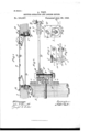
- Figure 1 is a plan section of a building-wall, window-casing, and shutter provided with my improved shutter-operating device Fig. 2, an enlarged broken vertical section, parallel to the jamb-lining, showing the engagement of the bevel-gears employed and the preferred means for journaling the same in the casing; Figs. 3 and 4, details of a hasp or latch employed, and Fig. 5 a detail of a locking means which may be employed for securing the bevel-gears in any desired position.
- A is a building-wall, recessed into which is a window-casing Q, which may be provided with a chamber for weights, as shown.
- a horizontally-disposed shaft 1 which is provided at the outer side of the jamb with a bearing-plate L, and at the inner side with a similar one.
- the shaft I is Serial No. 583,991. (No model.)
- a bevel-gear F, progle-irons J and K which may be secured to the jamb-post in any suitable manner, as by means of screws Z Z, or, if preferred, may be made integral with the bearing-plate L.
- the arm E carried by the gear F and rigidly attached thereto, is pivotally connected at its free end to a link D, preferably of two bars, provided toward their middle with a connecting-pin d and adapted to receive between them at one end the end of the arm E.
- a link D At its opposite end the link D is similarly pivoted to an eyebolt c, the shank of which passes through an opening in the shutter B.
- the shank of the eyebolt 0 (see Fig. 4) is provided witha head which, as here shown, may be formed by cutting recesses c in said shank.
- a latch or hasp 0 having a raised portion or handle 0 and a slot 0 and which is secured to the shutter by a bolt or rivet c.
- the slot 0 of the latch Chasits sidesfiaring and fits over the shank of the eyebolt at the reduced portion. This provision serves to guide the latch to place, and, if desired, the more readily to accomplish this purpose, the latch may be provided with an elongated opening for the reception of the pivot 0, thus allowing a short longitudinal movement of the latch as it is directed to its proper place.
- the angle 0 serves as a handle for the latch, by means of which the latter may be forced from its locked position, as by means of a pole or hatchet.
- Fig. 5 shows a detail of alocking mechanism employed. It consists of the lockingwheel M, firmly fixed to the shaft I, and a dog or pawl N, pivoted to the bearing-plate at the inner side of the jamb-post. sufficiently obvious.
- crank O Connected with the shaft I is a crank O or hand-wheel N.
- Thegear F carries the arm E, and in the operation of opening the shutter forces itoutward to bear against the pin 61 and so force open the shutter.
- the pawl N may be dropped upon the locking-wheel M to secure it in any desired position.
- the particularly valuable features of my invention are those which render the device compact and so allow its ready application to i any portion of the window-jamb without any particular provision for such application, and the provision for its ready detachment from the shutter from without the building in case of emergency.
- a shutter-operating device the com-f bination of a curved swinging arm, a link pivotally connected therewith and with the shutter, a stop upon said link adapted to be engaged by the swinging arm, and means for actuating said swinging arm, substantially as set forth.
- a shutter-operating device the combination of a bevel-gear, an arm carried by the gear and curved adjacent to its pointof attachment, a link pivotally connected with the free end of said arm and with the shutter, a stop upon said link adapted to be engaged by said arm at the beginning of its movement, and a shaft adapted to be held in the jambpost of the window and provided at one end with a bevel-gear to mesh with said first-mentioned bevel-gear and at the other end with operating means, all arranged substantially as and for the purpose set forth.
- a shutter operating device the combination of a swinging arm, curved as shown, and means for operating the same, a link pivotally connected with said arm at its free end, a stop upon said link adapted to be engaged by said arm at the beginning of its movement, and connecting means between said link and the shutter, comprising an eyebolt having a shank adapted to pass through a portion of the shutter and provided with a head, and a pivoted latch provided with a v slot having flaring sides adapted to engage said head, substantially as and for the purpose set forth.
Landscapes
- Operating, Guiding And Securing Of Roll- Type Closing Members (AREA)
Description
(No Model.)
A. VEIT. SHUTTER OPERATING VAND LOCKING DEVICE. No. 564,807. T Patented gu 28., 1896.
,. film/m emx) 'w l r l E W zraesaes: 2;: venfo r 409% ja a. 6%
UNITED STATES A N T O FFICE ANTON VEIT, OF CHICAGO, ILLINOIS.
SHUTTER OPERATING AND LOCKING DEVICE.
SPECIFICATION forming part of Letters Patent no. 564,807, dated July 28, 1896.
Application filed March 19, 1896.
To all whom it may concern:
Be it known that 1, ANTON VEIT, a citizen of the United States, residing at No. 255 Vine street, Chicago, county of Cook, State of Illinois, have invented a new and useful device for opening and closing shutters on buildings from the inside or outside without the necessity of raising the window-sash, of which the following is a specification.
My invention relates to an improvement in shutteroperating devices of the class designed to be operated from within a room without the necessity of raising the window.
My object is to provide a construction of apparatus which may be readily applied to a window at any part of the jamb desired, and this I accomplish by a novel arrangement of the levers connecting the shutter with the actuating mechanism, so that the same may be contained within the small space available between the closed shutter and the window.
A further object of my invention is to provide such an attachment for connecting the operating-levers to the shutter as to allow a ready detachment of the same from without the building should there be a necessity therefor, as in case of a fire or other emergency.
To the above ends my invention consists in the novel construction and arrangement of parts illustrated in the drawings, and hereinafter described and claimed;
In the drawings, Figure 1 is a plan section of a building-wall, window-casing, and shutter provided with my improved shutter-operating device Fig. 2, an enlarged broken vertical section, parallel to the jamb-lining, showing the engagement of the bevel-gears employed and the preferred means for journaling the same in the casing; Figs. 3 and 4, details of a hasp or latch employed, and Fig. 5 a detail of a locking means which may be employed for securing the bevel-gears in any desired position.
A is a building-wall, recessed into which is a window-casing Q, which may be provided with a chamber for weights, as shown. Through the casing or jamb-post passes a horizontally-disposed shaft 1, which is provided at the outer side of the jamb with a bearing-plate L, and at the inner side with a similar one. (Not shown.) The shaft I is Serial No. 583,991. (No model.)
A bevel-gear F, progle-irons J and K, which may be secured to the jamb-post in any suitable manner, as by means of screws Z Z, or, if preferred, may be made integral with the bearing-plate L.
The arm E, carried by the gear F and rigidly attached thereto, is pivotally connected at its free end to a link D, preferably of two bars, provided toward their middle with a connecting-pin d and adapted to receive between them at one end the end of the arm E. At its opposite end the link D is similarly pivoted to an eyebolt c, the shank of which passes through an opening in the shutter B. The shank of the eyebolt 0 (see Fig. 4) is provided witha head which, as here shown, may be formed by cutting recesses c in said shank.
To secure the eyebolt c to the shutter B, I provide a latch or hasp 0, having a raised portion or handle 0 and a slot 0 and which is secured to the shutter by a bolt or rivet c. The slot 0 of the latch Chasits sidesfiaring and fits over the shank of the eyebolt at the reduced portion. This provision serves to guide the latch to place, and, if desired, the more readily to accomplish this purpose, the latch may be provided with an elongated opening for the reception of the pivot 0, thus allowing a short longitudinal movement of the latch as it is directed to its proper place. The angle 0 serves as a handle for the latch, by means of which the latter may be forced from its locked position, as by means of a pole or hatchet.
Fig. 5 shows a detail of alocking mechanism employed. It consists of the lockingwheel M, firmly fixed to the shaft I, and a dog or pawl N, pivoted to the bearing-plate at the inner side of the jamb-post. sufficiently obvious.
Connected with the shaft I is a crank O or hand-wheel N.
Its operation is ICO By reference to Fig. 1 it will be seen that the gear-wheels above mentioned are close within the angle formed by the building w'all A and the jamb-post Q of the window. To allow, therefore, the armE to swing outward far enough to force the shutter around against the building-wall, the arm is made curved toward the end attached to the bevel-gear, so that it will fit around the angle of the wall when the shutter is in its wide open position. It will be seen that the effect of this arrangement is to enable the connecting-links to be contained within the comparatively small space between the shutter in its closed position and the window-pane P, since the long straight portion of the arm E is thereby brought into a position substantially parallel to the window when the shutter is closed. By this arrangement also the links are allowed to close together to a degree depending upon the position of the pin d, thus aiding materially in reducing the necessary contaming-space.
To operate the shutter, motion is communicated to the bevel-gears by means of the crank. Thegear F carries the arm E, and in the operation of opening the shutter forces itoutward to bear against the pin 61 and so force open the shutter. The pawl N may be dropped upon the locking-wheel M to secure it in any desired position.
The particularly valuable features of my invention are those which render the device compact and so allow its ready application to i any portion of the window-jamb without any particular provision for such application, and the provision for its ready detachment from the shutter from without the building in case of emergency.
What I claim as new, and desire to secure by Letters Patent, is
1. In a shutter-operating device, the com-f bination of a curved swinging arm, a link pivotally connected therewith and with the shutter, a stop upon said link adapted to be engaged by the swinging arm, and means for actuating said swinging arm, substantially as set forth.
2. In a shutter-operating device, the combination of a bevel-gear, an arm carried by the gear and curved adjacent to its pointof attachment, a link pivotally connected with the free end of said arm and with the shutter, a stop upon said link adapted to be engaged by said arm at the beginning of its movement, and a shaft adapted to be held in the jambpost of the window and provided at one end with a bevel-gear to mesh with said first-mentioned bevel-gear and at the other end with operating means, all arranged substantially as and for the purpose set forth.
'3. In a shutter-operating device, the combination with a swinging arm, and a link pivotally connected therewith, of connecting means between said link and the shutter, said connecting means being detachable from the closed shutter from without, substantially as described.
4:. In a shutter-operating device, the conibination with a swinging arm and a link pivotally connected therewith, of connecting means between said link and the shutter, comprising an eyebolt, having a shank adapted to pass through a portion of the shutter and provided with a head, and a latch adapted to engage said head, substantially as set forth. V
5. In a shutter operating device, the combination of a swinging arm, curved as shown, and means for operating the same, a link pivotally connected with said arm at its free end, a stop upon said link adapted to be engaged by said arm at the beginning of its movement, and connecting means between said link and the shutter, comprising an eyebolt having a shank adapted to pass through a portion of the shutter and provided with a head, and a pivoted latch provided with a v slot having flaring sides adapted to engage said head, substantially as and for the purpose set forth.
ANTON VEIT. lVitnesses:
JOHN F. SCHMITT, JOSEPH O. BOLTER.
Publications (1)
| Publication Number | Publication Date |
|---|---|
| US564807A true US564807A (en) | 1896-07-28 |
Family
ID=2633524
Family Applications (1)
| Application Number | Title | Priority Date | Filing Date |
|---|---|---|---|
| US564807D Expired - Lifetime US564807A (en) | Shutter operating and locking device |
Country Status (1)
| Country | Link |
|---|---|
| US (1) | US564807A (en) |
-
0
- US US564807D patent/US564807A/en not_active Expired - Lifetime
Similar Documents
| Publication | Publication Date | Title |
|---|---|---|
| US444730A (en) | Door-check | |
| US7856A (en) | Apparatus fob operating- window-blinds and their slats | |
| US189292A (en) | Improvement in blind-slat workers | |
| US298860A (en) | Blind-slat operator | |
| US952065A (en) | Device for operating blind-slats. | |
| US270340A (en) | Device for opening and closing skylights | |
| US374608A (en) | malloey | |
| US801506A (en) | Reversible window. | |
| US728288A (en) | Attachment for gates. | |
| US809779A (en) | Window-blind slat-fastener. | |
| US808486A (en) | Mechanism for operating casement windows, shutters, and the like. | |
| US371242A (en) | Shutter-worker | |
| US452084A (en) | Door-manipulator | |
| US696256A (en) | Gate. | |
| US1133332A (en) | Lock for car-doors. | |
| US891326A (en) | Device for operating shutters. | |
| US391573A (en) | Mechanism for operating shutters | |
| US660849A (en) | Lock strike and alarm. | |
| US193311A (en) | Improvement in combined shutter worker and fastener | |
| US328141A (en) | Shutter-worker | |
| US466901A (en) | John cahill | |
| US796673A (en) | Window-shutter worker and latch. | |
| US226045A (en) | Shutter-worker | |
| US639139A (en) | Transom-lifter. | |
| US337076A (en) | Feedeeick a |