US5638282A - Method and device for preventing collisions with the ground for an aircraft - Google Patents
Method and device for preventing collisions with the ground for an aircraft Download PDFInfo
- Publication number
- US5638282A US5638282A US08/542,645 US54264595A US5638282A US 5638282 A US5638282 A US 5638282A US 54264595 A US54264595 A US 54264595A US 5638282 A US5638282 A US 5638282A
- Authority
- US
- United States
- Prior art keywords
- aircraft
- altitude
- collision
- data
- ground
- Prior art date
- Legal status (The legal status is an assumption and is not a legal conclusion. Google has not performed a legal analysis and makes no representation as to the accuracy of the status listed.)
- Expired - Lifetime
Links
Images


Classifications
-
- G—PHYSICS
- G05—CONTROLLING; REGULATING
- G05D—SYSTEMS FOR CONTROLLING OR REGULATING NON-ELECTRIC VARIABLES
- G05D1/00—Control of position, course, altitude or attitude of land, water, air or space vehicles, e.g. using automatic pilots
- G05D1/04—Control of altitude or depth
- G05D1/06—Rate of change of altitude or depth
- G05D1/0607—Rate of change of altitude or depth specially adapted for aircraft
- G05D1/0653—Rate of change of altitude or depth specially adapted for aircraft during a phase of take-off or landing
-
- G—PHYSICS
- G01—MEASURING; TESTING
- G01C—MEASURING DISTANCES, LEVELS OR BEARINGS; SURVEYING; NAVIGATION; GYROSCOPIC INSTRUMENTS; PHOTOGRAMMETRY OR VIDEOGRAMMETRY
- G01C21/00—Navigation; Navigational instruments not provided for in groups G01C1/00 - G01C19/00
- G01C21/005—Navigation; Navigational instruments not provided for in groups G01C1/00 - G01C19/00 with correlation of navigation data from several sources, e.g. map or contour matching
-
- G—PHYSICS
- G01—MEASURING; TESTING
- G01S—RADIO DIRECTION-FINDING; RADIO NAVIGATION; DETERMINING DISTANCE OR VELOCITY BY USE OF RADIO WAVES; LOCATING OR PRESENCE-DETECTING BY USE OF THE REFLECTION OR RERADIATION OF RADIO WAVES; ANALOGOUS ARRANGEMENTS USING OTHER WAVES
- G01S13/00—Systems using the reflection or reradiation of radio waves, e.g. radar systems; Analogous systems using reflection or reradiation of waves whose nature or wavelength is irrelevant or unspecified
- G01S13/88—Radar or analogous systems specially adapted for specific applications
- G01S13/93—Radar or analogous systems specially adapted for specific applications for anti-collision purposes
- G01S13/933—Radar or analogous systems specially adapted for specific applications for anti-collision purposes of aircraft or spacecraft
- G01S13/935—Radar or analogous systems specially adapted for specific applications for anti-collision purposes of aircraft or spacecraft for terrain-avoidance
-
- G—PHYSICS
- G01—MEASURING; TESTING
- G01S—RADIO DIRECTION-FINDING; RADIO NAVIGATION; DETERMINING DISTANCE OR VELOCITY BY USE OF RADIO WAVES; LOCATING OR PRESENCE-DETECTING BY USE OF THE REFLECTION OR RERADIATION OF RADIO WAVES; ANALOGOUS ARRANGEMENTS USING OTHER WAVES
- G01S19/00—Satellite radio beacon positioning systems; Determining position, velocity or attitude using signals transmitted by such systems
- G01S19/01—Satellite radio beacon positioning systems transmitting time-stamped messages, e.g. GPS [Global Positioning System], GLONASS [Global Orbiting Navigation Satellite System] or GALILEO
- G01S19/13—Receivers
- G01S19/14—Receivers specially adapted for specific applications
- G01S19/15—Aircraft landing systems
-
- G—PHYSICS
- G01—MEASURING; TESTING
- G01S—RADIO DIRECTION-FINDING; RADIO NAVIGATION; DETERMINING DISTANCE OR VELOCITY BY USE OF RADIO WAVES; LOCATING OR PRESENCE-DETECTING BY USE OF THE REFLECTION OR RERADIATION OF RADIO WAVES; ANALOGOUS ARRANGEMENTS USING OTHER WAVES
- G01S19/00—Satellite radio beacon positioning systems; Determining position, velocity or attitude using signals transmitted by such systems
- G01S19/38—Determining a navigation solution using signals transmitted by a satellite radio beacon positioning system
- G01S19/39—Determining a navigation solution using signals transmitted by a satellite radio beacon positioning system the satellite radio beacon positioning system transmitting time-stamped messages, e.g. GPS [Global Positioning System], GLONASS [Global Orbiting Navigation Satellite System] or GALILEO
- G01S19/42—Determining position
- G01S19/45—Determining position by combining measurements of signals from the satellite radio beacon positioning system with a supplementary measurement
- G01S19/47—Determining position by combining measurements of signals from the satellite radio beacon positioning system with a supplementary measurement the supplementary measurement being an inertial measurement, e.g. tightly coupled inertial
-
- G—PHYSICS
- G05—CONTROLLING; REGULATING
- G05D—SYSTEMS FOR CONTROLLING OR REGULATING NON-ELECTRIC VARIABLES
- G05D1/00—Control of position, course, altitude or attitude of land, water, air or space vehicles, e.g. using automatic pilots
- G05D1/04—Control of altitude or depth
- G05D1/06—Rate of change of altitude or depth
- G05D1/0607—Rate of change of altitude or depth specially adapted for aircraft
- G05D1/0646—Rate of change of altitude or depth specially adapted for aircraft to follow the profile of undulating ground
-
- G—PHYSICS
- G08—SIGNALLING
- G08G—TRAFFIC CONTROL SYSTEMS
- G08G5/00—Traffic control systems for aircraft
- G08G5/20—Arrangements for acquiring, generating, sharing or displaying traffic information
- G08G5/26—Transmission of traffic-related information between aircraft and ground stations
-
- G—PHYSICS
- G08—SIGNALLING
- G08G—TRAFFIC CONTROL SYSTEMS
- G08G5/00—Traffic control systems for aircraft
- G08G5/70—Arrangements for monitoring traffic-related situations or conditions
- G08G5/74—Arrangements for monitoring traffic-related situations or conditions for monitoring terrain
-
- G—PHYSICS
- G08—SIGNALLING
- G08G—TRAFFIC CONTROL SYSTEMS
- G08G5/00—Traffic control systems for aircraft
- G08G5/80—Anti-collision systems
Definitions
- the invention concerns the general field of aids for aerial navigation.
- aids include in particular means making it possible for the aircraft crew to know its position and means intended to establish its altitude relative to the ground.
- the majority of aircraft are now equipped with an inertial unit which allows them to determine their position after any interval from take-off.
- the inertial unit provides the components of the velocity and acceleration vectors of the aircraft as well as the components of the associated angles. It is possible to derive position data therefrom but with a certain drift.
- the position data thus obtained may be compared with those provided by other radio navigational means.
- measurements of the type of system called "Global Positioning System” or GPS are used with Kalman's filtering. This may finally give fairly precise position data of latitude and longitude. The drift is more important for the altitude.
- a radio altimeter gives the height of the aircraft relative to the ground, or the "radio-altimeter height"; but this is an instantaneous local value: its characteristics depend on the attitude of the aircraft, since the latter affects the way the beam from the radio-altimeter strikes the ground. Moreover, from such a value one cannot predict the future progress.
- a second main object of the invention is to provide for this purpose an on-board device which is not sensitive to the prevailing meteorological conditions but is capable of functioning on a continuous basis and which is, in operation, independent of the information, control and safety systems installed on the ground.
- a third main object of the invention is to propose to the pilot an avoidance manoeuvre in the case of a dangerous situation and possibly to automate such a manoeuvre in certain cases.
- the invention also has the object of improving the ergonomics and safety of piloting an aircraft.
- Another important object of the invention is to permit a regular updating or resetting of a terrain file from data acquired by a group of aircraft equipped according to the invention.
- a device which includes a mass memory capable of storing a data base representing at least a substantial part of the terrestrial globe, in a cutout form comprising a grid configuration on at least one level.
- this grid configuration includes basic grids, intermediate grids subdividing certain basic grids and ultimate grids subdividing in turn some of the intermediate grids. These intermediate and ultimate grids are provided at least in the vicinity of airport zones.
- Each grid is associated with at least one data item representing the maximum altitude inside the grid. Provision is, moreover made for a reading means by means of at least one index permitting rapid access to sets of contiguous grids contained in the said data base, in accordance with a system of addressing horizontal coordinates, such as latitude and longitude.
- the device also includes an input for receiving status indications, expressed for example in geographical coordinates, and including in particular the latitude, longitude, altitude, and the velocity and acceleration vectors of the aircraft, optionally with the associated angles. At the input, there are also received the control indications coming from the flight deck.
- status indications expressed for example in geographical coordinates, and including in particular the latitude, longitude, altitude, and the velocity and acceleration vectors of the aircraft, optionally with the associated angles.
- the control indications coming from the flight deck.
- the data base is managed by electronic means. In accordance with the said status indications they will extract and transfer data constituting a temporary local map (a geographical map) into a fast access memory. This map defines an altitude envelope of the terrain in the zone where the aircraft is progressing.
- processing means will process the said status data so as to estimate a plurality of predicted points of the flight path of the aircraft; at each point, they will compare the contour of a protection field around the aircraft with the altitude envelope in the corresponding portion of the said local map; an alarm is established if the relation between the protection field and the altitude envelope meets a chosen condition (an anti-collision law).
- a chosen condition an anti-collision law.
- this condition is defined, at least partly, by means of an altitude safety margin and/or other control indications coming from the flight deck.
- the anti-collision law expresses the fact that the vertical distance between the protection field and the altitude envelope remains at least equal to the altitude safety margin for the predicted points of the flight path of the aircraft. Provision may be made for more elaborate conditions.
- the processing means are also arranged so as to emit a preliminary alarm indicating a risk of collision with the ground in the medium term, according to at least one anti-collision law of the ground (anti-ground impact law), specific to aircraft.
- anti-collision law of the ground (anti-ground impact law)
- This law may take account of the fact that the aircraft is flying in a straight line or in a turn.
- the means for managing the data base use a change in the points of reference in the zones surrounding the terrestrial poles. They also associate with the grids a dimension depending on the latitude in the direction of the terrestrial parallels.
- the grids are gathered into blocks or slabs, each block being associated with a reference altitude data item expressed as an absolute value, while the maximum altitude in each grid is expressed as a relative value in relation to an adjoining grid in accordance with a predetermined rule for passing through the grids within one block.
- each block has an overlap of at least one basic grid on two adjacent sides with its neighbours.
- the device includes means for displaying a synthetic image of the terrain in accordance with the contents of the local memory.
- the device includes means for comparing the terrain defined by the local memory with the terrain defined by the on-board instruments. The result of this comparison may be displayed and/or used to validate the operation of the device. Moreover, provision is made for means to store the divergences noted during the said comparison. After suitable cross-checks, these stored divergences will serve to update the basic terrain file maintained on the ground.
- the invention also provides a method for aiding the navigation of an aircraft. This method is subject to the same variants as is the device described above.
- FIG. 1 is a very general schematic diagram of a device in accordance with the invention.
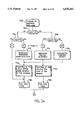
- FIG. 2 is a more detailed schematic diagram of a device in accordance with the invention.
- FIG. 3 is a still more detailed schematic, but partial diagram of a device in accordance with the invention.
- FIGS. 4A and 4B are two other detailed diagrams which, taken together (taking their cross-check into account) define a device in accordance with the invention
- FIG. 5 illustrates the definition of the grids in accordance with the invention
- FIG. 6 is a view in perspective showing the relation between two consecutive grids
- FIG. 7 shows the gathering of the grids into blocks
- FIGS. 8 and 9 show an overlapping of the blocks
- FIGS. 10a, 10b and 10c show different ways of calculating an absolute altitude from the data stored in the memory for the blocks
- FIGS. 11 and 12 illustrate the principle of a way of checking the altitude stored in the memory.
- FIG. 13 illustrates an uncertainty range
- FIG. 14 illustrates the uncertainty related to the flight path of the aircraft
- FIGS. 15a and 15b respectively illustrate a predicted flight path and an altitude profile coupled with a margin corresponding thereto;
- FIG. 16 schematically outlines the progress of the position of an aircraft in relation to a map contained in a local memory
- FIGS. 17a and 17b illustrate the determination of the relation between the position of the aircraft and the contents of the local memory
- FIG. 18 illustrates an example of an anti-collision protection curve
- FIGS. 19 and 20 are views in a vertical section illustrating different situations relative to an obstacle
- FIG. 21 is an example of an avoidance flight path
- FIGS. 22A and 22B illustrate two curves of the terrain
- FIGS. 23A, and 23B illustrate two divergence signals relating to the curves of the terrain of FIGS. 22A and 22B;
- FIG. 24 illustrates a mechanism for analyzing these divergence signals.
- flight deck refers to the functions necessary for the piloting, irrespective as to whether the latter are effected manually or automatically.
- functions necessary for the piloting there is to be understood, in particular, the functions of piloting proper and also the navigational functions. On another level one may distinguish between the functions themselves and their man/machine interface.
- the device in accordance with the invention is mainly intended to be installed on board an aircraft.
- the latter includes equipment 2 capable of providing indications of the flight parameters in the form of electric signals, that is to say, (FIG. 3):
- INU certified equipment
- the inertial unit 20 provides the components of the vectors of velocity (V) and acceleration ( ⁇ ) of the aircraft.
- V vectors of velocity
- ⁇ acceleration
- the inertial unit measures and/or uses certain of these angles for determining the velocity and acceleration vectors, it is preferable to collect the values of the said angles directly from the inertial unit, where it is used for operating the invention. These angular values may be displayed and/or used in the vicinity of the flight deck.
- the inertial unit cooperates in the known way with a barometric altimeter (not shown).
- Zb is the barometric altitude given by the measurement of the atmospheric pressure, and varies according to the altitude and the meteorological conditions
- Zi is the inertial altitude calculated by the double integration of the vertical acceleration measured by the accelerometers of the inertial unit (long-term variations),
- Zbi is the baro-inertial altitude, that is to say, Zb filtered by Zi (a third order loop, for example),
- Zc will be the computed altitude (HRS+Zta) where HRS is the radio altimeter height given by the radio altimeter or radio altimeters of the aircraft (accuracy of a few meters), and Zta will be the altitude of the terrain beneath the aircraft given by the terrain file (defined below),
- Zgps is the altitude provided by the GPS.
- aircraft are provided with an array of inertial units, and with a decision logic taking into account the indications from these units as a whole.
- the Applicant considers it at present preferable to take these data from only one of these units (to the extent that they are confirmed).
- a block 25 compares the two types of measurement and validates the values L1, G1, Z1, if they are consistent with L0, G0, Z0. Such validation techniques are known.
- the validated measurements L2, G2, Z2 are available at the time sequence p1. But they are upgraded from the inertial unit at a time sequence p2 of approximately one second.
- a block 28 extrapolates the data between the last instant of measurement by the instrument 21 and the current instant (this extrapolation is useful in particular in the case of problems with the time sequence of providing the data, which may be too slow).
- the radio altimeter 22 delivers the height above the ground, designated HRS.
- a block 3 contains a terrain file, established in a way that will be described below. In accordance with the values of L and G one gains access to a part of this file, called the local map and stored in a local memory 40 (FIG. 4A).
- the block 4 On the basis of this local map and the values of L, G, Z as well as HRS, the block 4 performs anti-collision calculations, preferably accompanied by ground avoidance calculations.
- an alarm (51) is emitted.
- An order director 53 may suggest an avoidance manoeuvre. The destination of this is the flight deck.
- the local map may also be used for generating a synthetic image (60) with its visualization device 55.
- the memory 70 retains the map profile which is flown over according to the sequence of the data L, G, Z.
- the memory 71 retains the real profile flown over, taken from the height HRS. The divergence between these two profiles is calculated at 72.
- the storing of the data MDF in a memory 79 in accordance with the values L and G in respect of which they have appeared.
- These data MDF may then serve as the basis, after the flight, for the updating effected in the system 10 of FIG. 4A.
- analysis block 77 will effect a correlation of the two inputs, but while taking into account:
- the present invention requires a preparation on the ground effected at regular intervals.
- the functions (3) of processing the terrain file are installed on board the aircraft. They use a mass memory 30 capable of accommodating a terrain data base BDT. With this mass memory 30, there are associated an updating interface 32, a device 35 for managing the data base, as well as a device 37 for the decompression of the data of the base.
- a data processing device 10 ensures filling and updating of the data base 30 through the interface 32 from the data coming from a very detailed electronic terrain file.
- a block 12 which defines a parameter system for adapting the use of the terrain file to a given aircraft and subsequently transmits these data:
- anticollision computer 43 for determining the parameters of the anti-collision laws and avoidance laws if applicable
- the visualization device 60 for adapting the visualization to the dynamic characteristics of the aircraft.
- the terrain file on the ground may be regularly updated by means of suitably checked return data MDF.
- the block 35 for managing the data base uses at least one index which may be stored in the mass memory 30, so as to permit the identification of, and fast access to, the data contained in the data base BDT.
- the flight deck 90 also provides informations which include at least the definition of an altitude safety margin MCZ transmitted to the block 43. Preferably, there is added thereto an "input status word" indicating:
- the characteristics in particular the flight characteristics of the aircraft.
- flight deck 90 may define adjustments for the synthetic imagery of the block 60.
- One of the essential fundamentals of the present invention is the fact that Applicants have recognized the possibility of storing on board an aircraft a terrain file capable of representing practically the whole of the terrestrial block, within the limits of the contour and resolution suitable for the requirements of an aircraft.
- the stored data are defined in low resolution elementary grids MBR which exist for the whole geographical domain covered by the data base.
- the MBR grid may be broken down into medium resolution grids MMR which in turn may be broken down (for example, in the immediate vicinity of the airport) into high resolution grids MHR.
- FIG. 6 shows that with each grid, irrespective of its resolution, there is associated a digital value representing the altitude of the highest point situated inside the grid (it is recalled that the file on the ground is much more detailed).
- FIGS. 7 to 9 the words “horizontal” and “vertical” here refer to the plane of the Figure).
- the essential element for the definition of the altitude values is the "block" of FIG. 7.
- One block (identified by the indices M and N) comprises a rectangle of ME ⁇ ME elementary grids.
- ME is, for example, of the order of 50.
- the cutting down into blocks is effected so that two consecutive blocks vertically overlap over a wide column of a grid (FIG. 8) and horizontally over a tall row of a grid (FIG. 9).
- FIG. 10a shows how the altitude Z A of the elementary grid i A , j A in a block is determined by means of a formula (I) (see the Annex of Formulae at the end of the description).
- FIG. 10b illustrates how the altitude of the same point is determined from the block situated above, in conjunction with formula (II).
- FIG. 10c and formula (III) show how the altitude of the same point is again determined from the block situated on the right-hand side.
- FIG. 11 and the formulae (IV) illustrate the vertical check between two consecutive blocks (in the overlapping row).
- FIG. 12 and the formulae (V) illustrate the same check but for two horizontally consecutive blocks in their overlapping column.
- each data item can be coded over four bits (at most).
- planar surfaces in particular the large expanses of the seas practically do not require any coding (at the level of the grid);
- the decompressing functions of the block 37 then lie in restoring in the memory 40 the absolute altitudes by means of the formulae described above (as a whole or in part, according to the degree of verification desired), taking into account any possible upgrading of the coding.
- the terrain file contains the altitudes of points of the terrain at the nodes of a grid of blocks and grids, with a mode of addressing or access to the data starting from the geographical coordinates of latitude (L) and longitude (G).
- the uncertainty depends on the equipment available on board the aircraft.
- an inertial unit even an excellent one, would have a drift of at least 10 kilometers at the end of some ten hours of flight.
- the coordinates of longitude, latitude G and L are vitiated by an uncertainty which is that of the GPS equipment, that is to say, approximately 100 meters or better.
- the terrain file is also subject to uncertainties.
- the volume of uncertainty resulting therefrom is an ellipsoid of revolution whose half axes a, b and c are not necessarily equal (FIG. 13).
- an uncertainty range is associated with each point of the flight path of the aircraft.
- ML MG.
- an uncertainty circle of navigation CIN an ellipse in the general case.
- the envelope of these circles in turn defines a flight zone ZV round the predicted flight path TVS.
- the future flight path of the aircraft is defined by a certain number of points A to F starting from its actual position, as illustrated in FIG. 15a.
- This future flight path is established from the current position of the aircraft (LGZ) and its velocity and acceleration vectors, associated with the respective angles defining the attitude of the aircraft.
- the status vector of the aircraft (position and velocity) is positioned in the trihedron of coordinates attached to the ground, wherein the BDT file is defined.
- the "square surface" of uncertainty (constituted by the grids surrounding the uncertainty range) has therefore m ⁇ m grids as its maximum dimensions.
- the predicted flight path includes p points, it is then necessary to have available in the local memory 40 at least p times this surface in absolute altitudes.
- FIG. 16 schematically illustrates the progress of the position of the aircraft, in relation to the grids contained in the local memory.
- the updating of the local memory may be effected by retaining the region wherein the aircraft is situated and by updating the three adjoining regions as illustrated in FIG. 16 by a dashed line.
- the set of values ZTM on the map will give the theoretical profile beneath the aircraft, and the effect of the anti-collision law is to compare this theoretical profile beneath the aircraft with the predicted flight path of the aircraft.
- This mode of operating gives particular satisfaction in the case of an automatic pilot flight, because this predicted flight path is known more precisely.
- CMT medium term curve mainly intended to forewarn the pilot that the flight path of his aircraft will encounter an obstacle if it is continued as it is and that he must consider an avoidance manoeuvre (preliminary alarm).
- FIG. 19 shows an example of an absence of a false alarm.
- FIG. 20 a case of a pertinent alarm is illustrated in FIG. 20. The small difference between these two drawings shows the difficulty of the problem solved by the invention.
- the proposed device may be provided with a device for calculating an avoidance law effected in the block 48 by means of various parameters coming from the blocks 43, 46 and 40. For example, in the case of an alarm, an order is generated for the vertical disengagement of the aircraft. In general, the avoidance order will take into account in particular:
- This avoidance order may be displayed on the order director (block 53) or be treated automatically.
- the avoidance flight path, proper whose radius of curvature RT is a direct function of the square of the linear velocity of the aircraft, divided by the load factor really applied, i.e.
- ground avoidance procedures are known which rely not only on manoeuvres in the vertical plane but also manoeuvres in the horizontal plane.
- Such devices are currently used for certain types of fast aircraft and can be easily transferred to civilian aircraft, subject to having available a suitable computing power, it being observed that the problem of civilian aircraft is far less difficult than that already dealt with in ground avoidance.
- the block for generating a synthetic image (60, FIG. 4B) remains to be considered.
- the latter may be made in any appropriate manner, in particular in the way described in the French patent No. 82 05121 (FR-A-2524177) or its certificate of addition No. 83 16580 (FR-A-2553543) both in the name of Applicants' assignees.
- FIG. 22A An example of the height of a terrain curve as provided by the memory 70 is illustrated in FIG. 22A.
- the block 72 calculates two divergences:
- ⁇ P2 which is for example, ⁇ P1 adjusted and filtered, or any other appropriate processing of ⁇ P1.
- FIGS. 23A and 23B illustrate the two divergences and their thresholds, to show four situations or different cases A to D.
- FIG. 24 illustrates a simplified example of the mechanism for analyzing anomalies. It is assumed that the radio altimeter height HRS is valid (taking into account the indications given above).
- a test 7702 compares the absolute value of ⁇ P1 with S1. Subsequently, a test compares the absolute value of ⁇ P2 with S2 (a separate test at 7704 and 7706, according to the result of 7702, for the clarity of the drawing).
- a test compares the absolute value of ⁇ P2 with S2 (a separate test at 7704 and 7706, according to the result of 7702, for the clarity of the drawing).
- Step 7712 possibly searches whether this divergence is imputable to ZA (problem noted on the on-board instruments), or to ZT (a systematic bias of the terrain file BDT).
- step 7740 records in the memory 79 the values L, G and ⁇ P1, (possibly the result of step 7712), and this during the whole duration of the anomaly.
- VAL.NAV a systematic bias of the terrain file BDT
- step C if ⁇ P1>S1 and ⁇ P2>S2.
- the anomaly stems in principle from the interrogation of the terrain file BDT, either because of its addressing (the values L and/or G being vitiated by errors) or because of its contents. Normally a historical analysis will permit this to be decided (7714) according to the repetitiveness of the anomaly.
- step 7750 records in the memory 79 the values of L and G (possibly the result of step 7714), and this at least at the start of the anomaly.
- step 7785 with VAL.NAV. false.
- the step 7716 may check whether this involves a pointwise anomaly by examining the hypotheses of a pointwise error of the terrain file BDT, a pointwise malfunction of one of the on-board instruments (radio altimeter, GPS, inertial unit) or a flight over a pointwise obstacle not yet entered.
- step 7740 records the values L, G, and ⁇ P1 in the memory 79, (possibly the results of step 7716) and this during the whole duration of the anomaly.
- VAL.NAV true.
- the device of the invention may have to be inhibited, at least as far as its alarms are concerned. This is the case:
- IVS instrument landing stage
- the inhibition is advantageously rendered dynamic (the signal VAL.NAV. already referred to).
Landscapes
- Engineering & Computer Science (AREA)
- Radar, Positioning & Navigation (AREA)
- Remote Sensing (AREA)
- Physics & Mathematics (AREA)
- General Physics & Mathematics (AREA)
- Aviation & Aerospace Engineering (AREA)
- Computer Networks & Wireless Communication (AREA)
- Automation & Control Theory (AREA)
- Electromagnetism (AREA)
- Traffic Control Systems (AREA)
- Navigation (AREA)
- Air Bags (AREA)
- Position Fixing By Use Of Radio Waves (AREA)
- Radar Systems Or Details Thereof (AREA)
Abstract
A mass memory stores a data base representing at least a substantial part of the terrestrial globe, in accordance with a grid configuration on several levels, said grid configuration being in particular more precise in the vicinity of an airport. Status indications are received representing the position of the aircraft with two horizontal components, and the altitude, and the velocity and acceleration vectors of the aircraft, as well as control indications coming from the flight deck. In accordance with the horizontal components of the position of the aircraft, a temporary local map is transferred into a fast access memory, on the basis of which map, an altitude envelope of the terrain is established in the zone where the aircraft is travelling. Anticollision processing make it possible to establish an alarm if the relation between a protection field and the altitude envelope meets a first condition which is defined at least partly by the control indications. The device has application as an aid for aerial navigation.
Description
This application is a continuation of application Ser. No. 08/041,870, filed Apr. 2, 1993 now U.S. Pat. No. 5,488,563.
The invention concerns the general field of aids for aerial navigation.
These aids include in particular means making it possible for the aircraft crew to know its position and means intended to establish its altitude relative to the ground.
The majority of aircraft are now equipped with an inertial unit which allows them to determine their position after any interval from take-off. The inertial unit provides the components of the velocity and acceleration vectors of the aircraft as well as the components of the associated angles. It is possible to derive position data therefrom but with a certain drift.
The position data thus obtained may be compared with those provided by other radio navigational means. For example, measurements of the type of system called "Global Positioning System" or GPS are used with Kalman's filtering. This may finally give fairly precise position data of latitude and longitude. The drift is more important for the altitude.
Measuring the altitude of the aircraft is, in fact, more difficult. The altitude relative to sea level is known by measurement means called "baro-inertial means"; but they are dependent on periodical resetting.
Apart from this, a radio altimeter gives the height of the aircraft relative to the ground, or the "radio-altimeter height"; but this is an instantaneous local value: its characteristics depend on the attitude of the aircraft, since the latter affects the way the beam from the radio-altimeter strikes the ground. Moreover, from such a value one cannot predict the future progress.
These measurements are sufficient during the cruising stage of the flight, at least if one is certain that the aircraft is progressing at a high altitude.
In any case, a problem does arise during the approach preliminary to landing, as well as after take-off: in these two cases, the aircraft is necessarily close to the ground, which implies an aggravated risk of ground impact. To deal with these particular difficulties relating to landing and take-off, it has been proposed to rely on ground proximity warning systems, with the acronym of GPWS (not to be confused with the positioning systems termed GPS).
These GPWS systems offer some progress but are not altogether satisfactory.
It is a primary object of the present invention to provide another solution to this problem from a radically different approach.
It is a further general object of the invention to permit the aircraft to avoid collision with the ground over which it is flying, in all hazardous circumstances.
More precisely it is a first main object of the invention to make it possible to ensure that the aircraft is at no time in an immediately dangerous position in relation to the ground. It is a subsidiary object to provide means for checking that the short-term flight path of the aircraft does not lead it into a dangerous position relative to the ground.
A second main object of the invention is to provide for this purpose an on-board device which is not sensitive to the prevailing meteorological conditions but is capable of functioning on a continuous basis and which is, in operation, independent of the information, control and safety systems installed on the ground.
A third main object of the invention is to propose to the pilot an avoidance manoeuvre in the case of a dangerous situation and possibly to automate such a manoeuvre in certain cases.
It is also an object of the invention to provide the pilot with a synthetic image of the terrain at a visibility distance in real time.
The invention also has the object of improving the ergonomics and safety of piloting an aircraft.
Another important object of the invention is to permit a regular updating or resetting of a terrain file from data acquired by a group of aircraft equipped according to the invention.
According to a first aspect of the invention, there is provided a device which includes a mass memory capable of storing a data base representing at least a substantial part of the terrestrial globe, in a cutout form comprising a grid configuration on at least one level. Advantageously, this grid configuration includes basic grids, intermediate grids subdividing certain basic grids and ultimate grids subdividing in turn some of the intermediate grids. These intermediate and ultimate grids are provided at least in the vicinity of airport zones.
Each grid is associated with at least one data item representing the maximum altitude inside the grid. Provision is, moreover made for a reading means by means of at least one index permitting rapid access to sets of contiguous grids contained in the said data base, in accordance with a system of addressing horizontal coordinates, such as latitude and longitude.
The device also includes an input for receiving status indications, expressed for example in geographical coordinates, and including in particular the latitude, longitude, altitude, and the velocity and acceleration vectors of the aircraft, optionally with the associated angles. At the input, there are also received the control indications coming from the flight deck.
The data base is managed by electronic means. In accordance with the said status indications they will extract and transfer data constituting a temporary local map (a geographical map) into a fast access memory. This map defines an altitude envelope of the terrain in the zone where the aircraft is progressing.
Finally, processing means will process the said status data so as to estimate a plurality of predicted points of the flight path of the aircraft; at each point, they will compare the contour of a protection field around the aircraft with the altitude envelope in the corresponding portion of the said local map; an alarm is established if the relation between the protection field and the altitude envelope meets a chosen condition (an anti-collision law). Preferably, this condition is defined, at least partly, by means of an altitude safety margin and/or other control indications coming from the flight deck.
In particular, the anti-collision law expresses the fact that the vertical distance between the protection field and the altitude envelope remains at least equal to the altitude safety margin for the predicted points of the flight path of the aircraft. Provision may be made for more elaborate conditions.
According to another aspect of the invention, the processing means are also arranged so as to emit a preliminary alarm indicating a risk of collision with the ground in the medium term, according to at least one anti-collision law of the ground (anti-ground impact law), specific to aircraft. This law may take account of the fact that the aircraft is flying in a straight line or in a turn.
Preferably, the means for managing the data base use a change in the points of reference in the zones surrounding the terrestrial poles. They also associate with the grids a dimension depending on the latitude in the direction of the terrestrial parallels.
Very advantageously, the grids are gathered into blocks or slabs, each block being associated with a reference altitude data item expressed as an absolute value, while the maximum altitude in each grid is expressed as a relative value in relation to an adjoining grid in accordance with a predetermined rule for passing through the grids within one block. Preferably, each block has an overlap of at least one basic grid on two adjacent sides with its neighbours.
According to another aspect of the invention, the device includes means for displaying a synthetic image of the terrain in accordance with the contents of the local memory.
A particularly advantageous aspect of the invention will now be dealt with. In flight, the device includes means for comparing the terrain defined by the local memory with the terrain defined by the on-board instruments. The result of this comparison may be displayed and/or used to validate the operation of the device. Moreover, provision is made for means to store the divergences noted during the said comparison. After suitable cross-checks, these stored divergences will serve to update the basic terrain file maintained on the ground.
The invention also provides a method for aiding the navigation of an aircraft. This method is subject to the same variants as is the device described above.
Other objects and advantages of the invention will emerge on examining the detailed description given below and the attached drawings wherein:
FIG. 1 is a very general schematic diagram of a device in accordance with the invention;
FIG. 2 is a more detailed schematic diagram of a device in accordance with the invention;
FIG. 3 is a still more detailed schematic, but partial diagram of a device in accordance with the invention;
FIGS. 4A and 4B are two other detailed diagrams which, taken together (taking their cross-check into account) define a device in accordance with the invention;
FIG. 5 illustrates the definition of the grids in accordance with the invention;
FIG. 6 is a view in perspective showing the relation between two consecutive grids;
FIG. 7 shows the gathering of the grids into blocks;
FIGS. 8 and 9 show an overlapping of the blocks;
FIGS. 10a, 10b and 10c show different ways of calculating an absolute altitude from the data stored in the memory for the blocks;
FIGS. 11 and 12 illustrate the principle of a way of checking the altitude stored in the memory.
FIG. 13 illustrates an uncertainty range;
FIG. 14 illustrates the uncertainty related to the flight path of the aircraft;
FIGS. 15a and 15b respectively illustrate a predicted flight path and an altitude profile coupled with a margin corresponding thereto;
FIG. 16 schematically outlines the progress of the position of an aircraft in relation to a map contained in a local memory;
FIGS. 17a and 17b illustrate the determination of the relation between the position of the aircraft and the contents of the local memory;
FIG. 18 illustrates an example of an anti-collision protection curve;
FIGS. 19 and 20 are views in a vertical section illustrating different situations relative to an obstacle;
FIG. 21 is an example of an avoidance flight path;
FIGS. 22A and 22B illustrate two curves of the terrain;
FIGS. 23A, and 23B illustrate two divergence signals relating to the curves of the terrain of FIGS. 22A and 22B; and
FIG. 24 illustrates a mechanism for analyzing these divergence signals.
The attached drawings are in essence of a definitive nature and therefore form an integral part of the present description. They may serve not only to render the latter more readily understood but also to contribute to the definition of the invention if required.
In general in the present description, the expression "flight deck" (or "control station") refers to the functions necessary for the piloting, irrespective as to whether the latter are effected manually or automatically. By functions necessary for the piloting there is to be understood, in particular, the functions of piloting proper and also the navigational functions. On another level one may distinguish between the functions themselves and their man/machine interface.
Reference is made to FIGS. 1 to 4B. The device in accordance with the invention is mainly intended to be installed on board an aircraft. The latter includes equipment 2 capable of providing indications of the flight parameters in the form of electric signals, that is to say, (FIG. 3):
an inertial unit 20 or INU ("certified" equipment),
a radionavigational instrument of the GPS type, designated 21, with its antenna ("uncertified" equipment),
a radio altimeter 22 with its antenna.
The inertial unit 20 provides the components of the vectors of velocity (V) and acceleration (γ) of the aircraft. One may deduce therefrom the associated characteristic angles: in particular, the angle of incidence, yaw, slope, pitch, heading, bank. However, inasmuch as the inertial unit measures and/or uses certain of these angles for determining the velocity and acceleration vectors, it is preferable to collect the values of the said angles directly from the inertial unit, where it is used for operating the invention. These angular values may be displayed and/or used in the vicinity of the flight deck.
For the altitude, the inertial unit cooperates in the known way with a barometric altimeter (not shown).
The following notations will be defined below:
Zb is the barometric altitude given by the measurement of the atmospheric pressure, and varies according to the altitude and the meteorological conditions,
Zi is the inertial altitude calculated by the double integration of the vertical acceleration measured by the accelerometers of the inertial unit (long-term variations),
Zbi is the baro-inertial altitude, that is to say, Zb filtered by Zi (a third order loop, for example),
Zc will be the computed altitude (HRS+Zta) where HRS is the radio altimeter height given by the radio altimeter or radio altimeters of the aircraft (accuracy of a few meters), and Zta will be the altitude of the terrain beneath the aircraft given by the terrain file (defined below),
Zgps is the altitude provided by the GPS.
Usually, aircraft are provided with an array of inertial units, and with a decision logic taking into account the indications from these units as a whole. For the operation of the invention, the Applicant considers it at present preferable to take these data from only one of these units (to the extent that they are confirmed).
The radionavigational instrument 21 provides uncorrected measurements of the latitude L1, longitude G1 and altitude Z1 (=Zgps) updated at a sequence p1 ranging from a few seconds to a few minutes. By integration of the velocity and acceleration vectors, the inertial unit 20 provides other measurements of the latitude L0, longitude G0 and altitude Z0 (=Zbi) which are less precise but come from "certified" equipment. A block 25 compares the two types of measurement and validates the values L1, G1, Z1, if they are consistent with L0, G0, Z0. Such validation techniques are known. The validated measurements L2, G2, Z2 are available at the time sequence p1. But they are upgraded from the inertial unit at a time sequence p2 of approximately one second.
A block 28 extrapolates the data between the last instant of measurement by the instrument 21 and the current instant (this extrapolation is useful in particular in the case of problems with the time sequence of providing the data, which may be too slow).
The radio altimeter 22 delivers the height above the ground, designated HRS.
A block 3 contains a terrain file, established in a way that will be described below. In accordance with the values of L and G one gains access to a part of this file, called the local map and stored in a local memory 40 (FIG. 4A).
On the basis of this local map and the values of L, G, Z as well as HRS, the block 4 performs anti-collision calculations, preferably accompanied by ground avoidance calculations.
In the presence of a collision risk, an alarm (51) is emitted. An order director 53 may suggest an avoidance manoeuvre. The destination of this is the flight deck.
The local map may also be used for generating a synthetic image (60) with its visualization device 55.
It will also serve for the functions (7) of validating the navigation and storing the divergence (or difference) data designated MDF.
These divergence are transferred to the bottom of the block 79 to the block 10, then they are sifted and serve for the total or partial updating of the data base 30.
The memory 70 retains the map profile which is flown over according to the sequence of the data L, G, Z. The memory 71 retains the real profile flown over, taken from the height HRS. The divergence between these two profiles is calculated at 72.
More precisely (FIG. 4B), the divergence is compared with two thresholds at 74 and 75 respectively. It is then analyzed (77), hence:
the actuation of a conformity indicator 57 confirming the proper functioning of the device;
the generation of a signal VAL.NAV., to validate the calculations of block 4; and
according to other criteria, the storing of the data MDF in a memory 79, in accordance with the values L and G in respect of which they have appeared. These data MDF may then serve as the basis, after the flight, for the updating effected in the system 10 of FIG. 4A.
In practice, the analysis block 77 will effect a correlation of the two inputs, but while taking into account:
the history (recent past) of the flight,
the estimated confidence in the data of the radio altimeter (limits of operation, taking into account the attitude of the aircraft, self-monitoring),
the transitory nature of the crossing of the threshold,
the analysis of the result (bias or noise or other),
possibly, adequate stored data.
The present invention requires a preparation on the ground effected at regular intervals.
The functions (3) of processing the terrain file are installed on board the aircraft. They use a mass memory 30 capable of accommodating a terrain data base BDT. With this mass memory 30, there are associated an updating interface 32, a device 35 for managing the data base, as well as a device 37 for the decompression of the data of the base.
On the ground, outside the aircraft, a data processing device 10 ensures filling and updating of the data base 30 through the interface 32 from the data coming from a very detailed electronic terrain file. Preferably, provision is also made on the ground for a block 12 which defines a parameter system for adapting the use of the terrain file to a given aircraft and subsequently transmits these data:
to the anticollision computer 43 for determining the parameters of the anti-collision laws and avoidance laws if applicable, and
to the visualization device 60 for adapting the visualization to the dynamic characteristics of the aircraft.
The terrain file on the ground may be regularly updated by means of suitably checked return data MDF.
Since the terrain data included in the data base 30 are compressed, their utilization requires the use of a decompression function which will be described below.
For its part, the block 35 for managing the data base uses at least one index which may be stored in the mass memory 30, so as to permit the identification of, and fast access to, the data contained in the data base BDT.
The flight deck 90 also provides informations which include at least the definition of an altitude safety margin MCZ transmitted to the block 43. Preferably, there is added thereto an "input status word" indicating:
whether the piloting is automatic or manual;
whether the aircraft is in a turn or in a straight line;
the characteristics (in particular the flight characteristics) of the aircraft.
Moreover, the flight deck 90 may define adjustments for the synthetic imagery of the block 60.
One of the essential fundamentals of the present invention is the fact that Applicants have recognized the possibility of storing on board an aircraft a terrain file capable of representing practically the whole of the terrestrial block, within the limits of the contour and resolution suitable for the requirements of an aircraft.
First of all (FIG. 5), the stored data are defined in low resolution elementary grids MBR which exist for the whole geographical domain covered by the data base.
In the vicinity of airports, or for other reasons, the MBR grid may be broken down into medium resolution grids MMR which in turn may be broken down (for example, in the immediate vicinity of the airport) into high resolution grids MHR.
FIG. 6 shows that with each grid, irrespective of its resolution, there is associated a digital value representing the altitude of the highest point situated inside the grid (it is recalled that the file on the ground is much more detailed).
Another important characteristic of the invention lies in the fact that these altitude values are not stored in an absolute form (compression).
To explain this, reference is made to FIGS. 7 to 9 (the words "horizontal" and "vertical" here refer to the plane of the Figure). The essential element for the definition of the altitude values is the "block" of FIG. 7. One block (identified by the indices M and N) comprises a rectangle of ME×ME elementary grids. ME is, for example, of the order of 50. The cutting down into blocks is effected so that two consecutive blocks vertically overlap over a wide column of a grid (FIG. 8) and horizontally over a tall row of a grid (FIG. 9).
According to the invention (FIG. 7), only the altitude Z11 concerning the elementary grid situated in the bottom left-hand corner of a block is stored in an absolute form, that is to say, with all its significant digits. All the other altitude values inside a block are stored in a relative mode (DEL-TAij), that is to say;
relative to the grid directly preceding it on the same line if this grid is in the block, or
relative to the grid immediately below if its location is the left-most grid of a line.
It will be observed that there obtains a redundancy of data because of the overlapping of the blocks.
Thus FIG. 10a shows how the altitude ZA of the elementary grid iA, jA in a block is determined by means of a formula (I) (see the Annex of Formulae at the end of the description).
FIG. 10b illustrates how the altitude of the same point is determined from the block situated above, in conjunction with formula (II).
FIG. 10c and formula (III) show how the altitude of the same point is again determined from the block situated on the right-hand side.
Moreover, this particularly advantageous mode of a compact representation of data permits complete checks between consecutive blocks. FIG. 11 and the formulae (IV) illustrate the vertical check between two consecutive blocks (in the overlapping row). FIG. 12 and the formulae (V) illustrate the same check but for two horizontally consecutive blocks in their overlapping column.
By storing the altitude data in the memory 30 in this way, the Applicant has observed that in the great majority of cases, each data item can be coded over four bits (at most).
Moreover, it is possible to limit these data:
planar surfaces; in particular the large expanses of the seas practically do not require any coding (at the level of the grid);
one may consider effecting the relative altitude coding with an accuracy (weighting of the least significant bit or LSB) depending on the altitude, proportionately for example;
possibly, the fact will be taken into account that certain zones of the terrestrial globe are never flown over.
From Applicants' studies, it follows that it is possible to integrate the surface of the terrestrial globe, that is to say, a surface of approximately 500 million square kilometers, with the grids of higher definition provided for 1000 airports, in a memory whose total size would be 200 megabits, which can be easily achieved with the present technology.
Once these data are stored, they are complemented by an index making it possible to locate rapidly, from the data expressed in geographical coordinates, the block or blocks relating to the zone wherein the aircraft is situated, then each of the relevant elementary grids and then (if required) the grids with a higher resolution, if there are any.
The decompressing functions of the block 37 then lie in restoring in the memory 40 the absolute altitudes by means of the formulae described above (as a whole or in part, according to the degree of verification desired), taking into account any possible upgrading of the coding.
Thus the terrain file contains the altitudes of points of the terrain at the nodes of a grid of blocks and grids, with a mode of addressing or access to the data starting from the geographical coordinates of latitude (L) and longitude (G).
In the region of the poles, it suffices to effect a change of reference to return to a conventional situation, such a change of reference being practically equivalent to exchanging the poles for two opposed points of the equator, for example. This indication will enable the expert to transpose the following discussion to apply it to the case of the poles.
The uncertainties, on the one hand at the level of the flight parameters, and on the other hand, at the level of the terrain file will now be examined.
As for the flight parameters, the uncertainty depends on the equipment available on board the aircraft.
An inertial unit, even an excellent one, would have a drift of at least 10 kilometers at the end of some ten hours of flight. Applicants recommend the use of an inertial unit of good quality, suitably reset relative to position indications coming from a device such as the GPS as described with reference to FIG. 3. In these conditions, the coordinates of longitude, latitude G and L, thus obtained, are vitiated by an uncertainty which is that of the GPS equipment, that is to say, approximately 100 meters or better.
The terrain file is also subject to uncertainties.
To deal with all the uncertainties, Applicants propose to define three uncertainty margins (FIG. 13):
an uncertainty margin in latitude ML,
an uncertainty margin in longitude MG, and
a vertical uncertainty margin MZ.
The volume of uncertainty resulting therefrom is an ellipsoid of revolution whose half axes a, b and c are not necessarily equal (FIG. 13).
Thus as illustrated in FIG. 14, an uncertainty range is associated with each point of the flight path of the aircraft. To simplify, it is assumed that ML=MG. In the vertical projection in the horizontal plane of FIG. 14, there is then obtained an uncertainty circle of navigation CIN (an ellipse in the general case). The envelope of these circles in turn defines a flight zone ZV round the predicted flight path TVS.
It is important to note that the vertical margin MZ is the sum of:
the adjustable value MZC coming from the flight deck or the block 4,
a margin linked to the uncertainties of the flight parameters as defined above, and
a margin linked to the intrinsic uncertainties of the altitude of the terrain file.
In practice, the uncertainties in the two horizontal dimensions (longitude and latitude) will be finally reflected in an uncertainty in the vertical margin: indeed, these horizontal uncertainties induce an uncertainty in the "addressing" of the terrain file, hence an uncertainty in altitude.
Starting from these considerations, Applicants have observed that it was possible to carry out calculations at a renewal sequence of the order of 1 Hertz, which may be adjusted according to the velocity and the piloting transfer function of the carrier aircraft. The Hertz sequence is suitable for velocities up to approximately 275 meters per second.
It is, for example, assumed that the future flight path of the aircraft is defined by a certain number of points A to F starting from its actual position, as illustrated in FIG. 15a. This future flight path is established from the current position of the aircraft (LGZ) and its velocity and acceleration vectors, associated with the respective angles defining the attitude of the aircraft. The status vector of the aircraft (position and velocity) is positioned in the trihedron of coordinates attached to the ground, wherein the BDT file is defined.
Taking into account the uncertainty range surrounding the predicted position of the aircraft (considered for the sake of simplification as a circle of radius R), and if c designates the side of the grid currently used (according to its resolution), the quantity m of grids whose altitude is to be tested is:
m=INT{2*([R*SQRT(2)/c]+1)}
where INT{ } designates the integral part function, and SQRT() the square root function. (FIGS. 17a and 17b).
At a given point, the "square surface" of uncertainty (constituted by the grids surrounding the uncertainty range) has therefore m×m grids as its maximum dimensions.
If the predicted flight path includes p points, it is then necessary to have available in the local memory 40 at least p times this surface in absolute altitudes.
Thus FIG. 16 schematically illustrates the progress of the position of the aircraft, in relation to the grids contained in the local memory.
The updating of the local memory may be effected by retaining the region wherein the aircraft is situated and by updating the three adjoining regions as illustrated in FIG. 16 by a dashed line.
With reference to FIGS. 17a and 17b, one considers the square uncertainty surface with maximum dimensions of m×m grids. All the altitudes are read and only the value of the highest altitude ZT will be retained and added to the altitude safety margin MZ defined above. The sum designated ZTM is illustrated in dashes.
The set of values ZTM on the map will give the theoretical profile beneath the aircraft, and the effect of the anti-collision law is to compare this theoretical profile beneath the aircraft with the predicted flight path of the aircraft.
This mode of operating gives particular satisfaction in the case of an automatic pilot flight, because this predicted flight path is known more precisely.
In the manual mode, the flight path of the aircraft is susceptible to more important variations.
The analysis of the instantaneous and predicted situation of the aircraft may then be summed up in a set of curve tests, capable of generating two types of alarm:
a preliminary alarm indicating a dangerous configuration in the medium term, and
an alarm indicating a configuration requiring immediate action from the pilot because the safety of the flight is placed in question.
For this purpose, provision is made for two curves for protecting the aircraft first and second anti-collision laws in relation to the terrain defined according to the same principle, but with different parameters and including (FIG. 18):
a short-term curve CCT mainly intended to avoid an accident. When a point of the terrain enters into the surface or upper envelope of the curve CCT, the pilot must intervene (alarm).
a medium term curve CMT mainly intended to forewarn the pilot that the flight path of his aircraft will encounter an obstacle if it is continued as it is and that he must consider an avoidance manoeuvre (preliminary alarm).
These curves which constitute an important element of the protection system may be elaborated from numerous static and dynamic parameters of the aircraft, in particular:
the piloting transfer function of the aircraft, that is to say, its capacity to manoeuvre,
the delays TRo due to the reaction time of the pilot of the aircraft;
the horizontal velocity Vh of the aircraft,
the ascent velocity Vz of the aircraft,
the admissible load factor n.g,
the height of the planned safety factor, and
the rolling of the aircraft.
FIG. 19 shows an example of an absence of a false alarm. On the other hand, a case of a pertinent alarm is illustrated in FIG. 20. The small difference between these two drawings shows the difficulty of the problem solved by the invention.
Secondly, when a possible collision with the ground has been detected, the proposed device may be provided with a device for calculating an avoidance law effected in the block 48 by means of various parameters coming from the blocks 43, 46 and 40. For example, in the case of an alarm, an order is generated for the vertical disengagement of the aircraft. In general, the avoidance order will take into account in particular:
the proximity of the danger
the velocity of the aircraft
its "manoeuvrability",
the pilot's reaction time,
the fuel reserves.
For various reasons, Applicants consider at present that it is preferable to effect a simple avoidance manoeuvre, constituted by an avoidance order in depth making it possible to ensure over flying of the terrain (with a straightening of the aircraft if necessary).
This avoidance order may be displayed on the order director (block 53) or be treated automatically.
Thus if, for the sake of simplification, a flight path in a straight line is taken, the avoidance limit curve will be defined by three sections (FIG. 21):
from T0 to T1, the continuation of the flight path as it is during a time equal to the delay RTO=T1 -T0,
from T1 to T2, a transitional period due to the change of radius of curvature of the flight path passing from infinity to the ascent radius RT,
from T2 to T3, the avoidance flight path, proper, whose radius of curvature RT is a direct function of the square of the linear velocity of the aircraft, divided by the load factor really applied, i.e.
R.sub.T =(V.sub.h).sup.2 /n.g
The expert knows that similar considerations make it possible to establish an avoidance manoeuvre in a turn but in a somewhat more complicated manner, into which it is here not necessary to enter into detail.
Examples of avoidance techniques are described in the French Patent Application No. 8617235 (FR-A-2607948) in the name of Applicants' assignees.
More generally, ground avoidance procedures are known which rely not only on manoeuvres in the vertical plane but also manoeuvres in the horizontal plane. Such devices are currently used for certain types of fast aircraft and can be easily transferred to civilian aircraft, subject to having available a suitable computing power, it being observed that the problem of civilian aircraft is far less difficult than that already dealt with in ground avoidance.
The block for generating a synthetic image (60, FIG. 4B) remains to be considered. The latter may be made in any appropriate manner, in particular in the way described in the French patent No. 82 05121 (FR-A-2524177) or its certificate of addition No. 83 16580 (FR-A-2553543) both in the name of Applicants' assignees.
The functions of the subassemblies of the block 7 have already been described in general terms. It will, first of all, be observed that this function only operates on past and present data. (L, G, Z and HRS), to the exclusion of predicted values.
An example of the height of a terrain curve as provided by the memory 70 is illustrated in FIG. 22A. For its part, FIG. 22B illustrates the calculation of the height of the terrain Zta=ZA-HRS in the memory 71.
The block 72 calculates two divergences:
δP1=ZT-ZA+HRS, and
δP2, which is for example, δP1 adjusted and filtered, or any other appropriate processing of δP1.
These two divergences are compared with respective thresholds S1 and S2. FIGS. 23A and 23B illustrate the two divergences and their thresholds, to show four situations or different cases A to D.
FIG. 24 illustrates a simplified example of the mechanism for analyzing anomalies. It is assumed that the radio altimeter height HRS is valid (taking into account the indications given above).
After the starting step 7700, a test 7702 compares the absolute value of δP1 with S1. Subsequently, a test compares the absolute value of δP2 with S2 (a separate test at 7704 and 7706, according to the result of 7702, for the clarity of the drawing). One then has:
Case A (normal), if δP1<=S1 and δP2<=S2, in which case, one passes directly to 7780 with VAL.NAV. true.
Case B, if δP1<=S1 and δP2>S2. The altitude Z is shifted. Step 7712 possibly searches whether this divergence is imputable to ZA (problem noted on the on-board instruments), or to ZT (a systematic bias of the terrain file BDT). In any case, step 7740 records in the memory 79 the values L, G and δP1, (possibly the result of step 7712), and this during the whole duration of the anomaly. One nevertheless continues at 7780 with VAL.NAV. true.
Case C, if δP1>S1 and δP2>S2. The anomaly stems in principle from the interrogation of the terrain file BDT, either because of its addressing (the values L and/or G being vitiated by errors) or because of its contents. Normally a historical analysis will permit this to be decided (7714) according to the repetitiveness of the anomaly. In this case, step 7750 records in the memory 79 the values of L and G (possibly the result of step 7714), and this at least at the start of the anomaly. One continues with step 7785 with VAL.NAV. false.
Case D, if δP1>S1 and δP2≦S2. The step 7716 may check whether this involves a pointwise anomaly by examining the hypotheses of a pointwise error of the terrain file BDT, a pointwise malfunction of one of the on-board instruments (radio altimeter, GPS, inertial unit) or a flight over a pointwise obstacle not yet entered. Here again, step 7740 records the values L, G, and δP1 in the memory 79, (possibly the results of step 7716) and this during the whole duration of the anomaly. One may continue at 7780 with VAL.NAV true.
As far as the use of the history of the anomalies in steps 7712 to 7716 is concerned, its advantage will be described below in an example. It will also become apparent that the characteristics of the terrain flown over, and in particular its inherent flatness, (derived from the measurement ZA--HRS) make it possible to improve the classification of the anomalies. In the example chosen, one passes from case A with δP1 close to 0) to case C where δP1 is very perturbed. The probable causes of the anomaly can then be analyzed as follows:
if the transition from A to C is accompanied by a transition from a flat terrain to a perturbed terrain, this very probably concerns an error in the navigational parameters.
in the other cases, this very probably concerns an error in the terrain file BDT, where one will distinguish three cases of shape: the terrain remains flat; one passes from a perturbed terrain to another perturbed terrain, but with the altitude being disrupted in the transition; one passes from a perturbed terrain to a flat terrain.
An analysis of the same kind may be undertaken with other transitions between the cases A to D.
Of course, the invention is susceptible to many variants and arrangements.
For example, in the immediate vicinity of the ground, the device of the invention may have to be inhibited, at least as far as its alarms are concerned. This is the case:
when the aircraft is in the instrument landing stage (ILS), or
at the pilot's express request.
The inhibition is advantageously rendered dynamic (the signal VAL.NAV. already referred to).
Moreover, it may be advantageous to use two terrain files 30, one for the relief fixed in time (natural altimetry), the other for erected and/or evolving obstacles (artificial altimetry). ##EQU1##
Claims (16)
1. In an aerial navigation aid device, the improvement comprising: (a) mass memory means for storing a data base representing at least a substantial part of the terrestrial globe, in a cutout form comprising a grid configuration having at least one level of resolution, each grid being associated with at least one data item representing the maximum altitude inside the grid, said data base having sets of contiguous grids, accessible in accordance with a system of addressing by two horizontal coordinates;
(b) input means for receiving status indications representing the position of the aircraft with two horizontal components and the altitude, and its velocity vector, defining the present flight path of the aircraft;
(c) a fast access working memory;
(d) management means, responsive to said status indications, for accessing said data base to maintain a temporary local map in said fast access working memory, said temporary local map corresponding to the zone wherein the aircraft is traveling, and defining a ground altitude envelope of the terrain in said zone;
(e) anti-collision means for determining whether the present flight path matches first and second anti-collision laws in relationship with said ground altitude envelope; and
(f) alarm means capable of selectively establishing a first alarm in accordance with a first condition, which includes the fact that said first anti-collision law is violated, and a second alarm in accordance with a second condition, which includes the fact that said second anti-collision law is violated.
2. A device according to claim 1, wherein the resolution of said temporary local map is variable, with a higher resolution being provided for, at least in the vicinity of airport zones.
3. A device according to claim 1, wherein said first and second anti-collision laws are specific to the aircraft.
4. A device according to claim 1, wherein the altitude in said position data comprises baro-inertial altitude.
5. A device according to claim 4, wherein the altitude in said position data comprises altitude data from an independent radionavigational source.
6. A device according to claim 1, wherein said two horizontal components in said position data are derived from the combination of a radionavigational instrument with an inertial on-board instrument.
7. A device according to claim 1, wherein said input means are arranged for receiving velocity vector data and acceleration vector data from on-board inertial instruments, and said anti-collision means takes account of said velocity vector data and acceleration vector data.
8. A device according to claim 1, wherein said input means are arranged for further receiving the attitude angles of the aircraft from on-board inertial instruments, and said anti-collision means takes account of said attitude angles of the aircraft.
9. A device according to claim 8, wherein said first and second anti-collision laws take account of the fact that the aircraft is in a straight line or is in a turn.
10. A device according to claim 9, wherein the attitude angles are derived from an inertial unit installed on-board the aircraft.
11. A device according to claim 1, wherein said first anti-collision law corresponds to an extrapolated piloting flight path for pulling-up with a virtually maximum amplitude after a brief delay, and said second anti-collision law corresponds to an extrapolated piloting flight path for pulling-up with a virtually maximum amplitude after a longer delay, whereby said first anti-collision law corresponds to a short term danger of ground collision, while said second anti-collision law corresponds to a medium term danger of ground collision.
12. A device according to claim 1, wherein said input means comprises first input means for receiving a first set of said two horizontal components from on-board inertial instruments, second input means for receiving a second set of said two horizontal components from an independent radionavigational source, and means for combining such two sets of said two horizontal components into a pair of enhanced precision horizontal components, for use in said management means.
13. A device according to claim 12, wherein said input means comprises third input means for receiving height to ground data, and means for influencing the operation of said anti-collision means in accordance with said height to ground data.
14. A device according to claim 13, wherein said independent radionavigational source is a GPS receiver.
15. A device according to claim 12, wherein said independent radionavigational source is a GPS receiver.
16. A device according to claim 12, wherein said means for combining comprises a Kalman filter.
Priority Applications (1)
| Application Number | Priority Date | Filing Date | Title |
|---|---|---|---|
| US08/542,645 US5638282A (en) | 1992-04-07 | 1995-10-13 | Method and device for preventing collisions with the ground for an aircraft |
Applications Claiming Priority (4)
| Application Number | Priority Date | Filing Date | Title |
|---|---|---|---|
| FR9504245 | 1992-04-07 | ||
| FR9204245A FR2689668B1 (en) | 1992-04-07 | 1992-04-07 | FIELD ANTI-COLLISION PROCESS AND DEVICE FOR AIRCRAFT. |
| US08/041,870 US5488563A (en) | 1992-04-07 | 1993-04-02 | Method and device for preventing collisions with the ground for an aircraft |
| US08/542,645 US5638282A (en) | 1992-04-07 | 1995-10-13 | Method and device for preventing collisions with the ground for an aircraft |
Related Parent Applications (1)
| Application Number | Title | Priority Date | Filing Date |
|---|---|---|---|
| US08/041,870 Continuation US5488563A (en) | 1992-04-07 | 1993-04-02 | Method and device for preventing collisions with the ground for an aircraft |
Publications (1)
| Publication Number | Publication Date |
|---|---|
| US5638282A true US5638282A (en) | 1997-06-10 |
Family
ID=9428589
Family Applications (2)
| Application Number | Title | Priority Date | Filing Date |
|---|---|---|---|
| US08/041,870 Expired - Lifetime US5488563A (en) | 1992-04-07 | 1993-04-02 | Method and device for preventing collisions with the ground for an aircraft |
| US08/542,645 Expired - Lifetime US5638282A (en) | 1992-04-07 | 1995-10-13 | Method and device for preventing collisions with the ground for an aircraft |
Family Applications Before (1)
| Application Number | Title | Priority Date | Filing Date |
|---|---|---|---|
| US08/041,870 Expired - Lifetime US5488563A (en) | 1992-04-07 | 1993-04-02 | Method and device for preventing collisions with the ground for an aircraft |
Country Status (11)
| Country | Link |
|---|---|
| US (2) | US5488563A (en) |
| EP (1) | EP0565399B1 (en) |
| JP (1) | JPH0624393A (en) |
| AT (1) | ATE147869T1 (en) |
| CA (1) | CA2093546C (en) |
| DE (1) | DE69307377T2 (en) |
| DK (1) | DK0565399T3 (en) |
| ES (1) | ES2099391T3 (en) |
| FR (1) | FR2689668B1 (en) |
| GR (1) | GR3022297T3 (en) |
| RU (1) | RU2124760C1 (en) |
Cited By (69)
| Publication number | Priority date | Publication date | Assignee | Title |
|---|---|---|---|---|
| US5839080A (en) * | 1995-07-31 | 1998-11-17 | Alliedsignal, Inc. | Terrain awareness system |
| US6002347A (en) * | 1996-04-23 | 1999-12-14 | Alliedsignal Inc. | Integrated hazard avoidance system |
| US6076042A (en) * | 1996-04-29 | 2000-06-13 | Sun Microsystems, Inc. | Altitude sparse aircraft display |
| FR2787907A1 (en) * | 1998-12-23 | 2000-06-30 | Sextant Avionique | AID SYSTEM FOR AVOIDING AIRCRAFT COLLISIONS WITH THE GROUND |
| US6088654A (en) * | 1998-01-12 | 2000-07-11 | Dassault Electronique | Terrain anti-collision process and device for aircraft, with improved display |
| US6092009A (en) * | 1995-07-31 | 2000-07-18 | Alliedsignal | Aircraft terrain information system |
| US6138060A (en) * | 1995-07-31 | 2000-10-24 | Alliedsignal Inc. | Terrain awareness system |
| US6259976B1 (en) | 1999-09-25 | 2001-07-10 | Jerome H. Lemelson | Fuzzy logic based emergency flight control with thrust vectoring |
| US6292721B1 (en) | 1995-07-31 | 2001-09-18 | Allied Signal Inc. | Premature descent into terrain visual awareness enhancement to EGPWS |
| US6380870B1 (en) | 1999-02-01 | 2002-04-30 | Honeywell International, Inc. | Apparatus, methods, and computer program products for determining a look ahead distance value for high speed flight |
| US6421603B1 (en) | 1999-08-11 | 2002-07-16 | Honeywell International Inc. | Hazard detection for a travel plan |
| US20020111740A1 (en) * | 2000-10-25 | 2002-08-15 | United Parcel Service Of America, Inc. | Pilot-programmable altitude range filter for cockpit traffic display |
| US6445310B1 (en) | 1999-02-01 | 2002-09-03 | Honeywell International, Inc. | Apparatus, methods, computer program products for generating a runway field clearance floor envelope about a selected runway |
| US6469660B1 (en) | 2000-04-13 | 2002-10-22 | United Parcel Service Inc | Method and system for displaying target icons correlated to target data integrity |
| US6469664B1 (en) | 1999-10-05 | 2002-10-22 | Honeywell International Inc. | Method, apparatus, and computer program products for alerting surface vessels to hazardous conditions |
| US6477449B1 (en) | 1999-02-01 | 2002-11-05 | Honeywell International Inc. | Methods, apparatus and computer program products for determining a corrected distance between an aircraft and a selected runway |
| US6484071B1 (en) | 1999-02-01 | 2002-11-19 | Honeywell International, Inc. | Ground proximity warning system, method and computer program product for controllably altering the base width of an alert envelope |
| US6507289B1 (en) * | 1999-10-05 | 2003-01-14 | Honeywell International Inc. | Apparatus and method of checking radio altitude reasonableness |
| US6606034B1 (en) | 1995-07-31 | 2003-08-12 | Honeywell International Inc. | Terrain awareness system |
| US6643580B1 (en) | 1998-10-16 | 2003-11-04 | Universal Avionics Systems Corporation | Flight plan intent alert system and method |
| BE1014538A3 (en) * | 2001-12-13 | 2003-12-02 | Brigode Philippe L | Method and device for monitoring and control automatic path of an aircraft. |
| US6687606B1 (en) | 2002-02-21 | 2004-02-03 | Lockheed Martin Corporation | Architecture for automatic evaluation of team reconnaissance and surveillance plans |
| US6691004B2 (en) | 1995-07-31 | 2004-02-10 | Honeywell International, Inc. | Method for determining a currently obtainable climb gradient of an aircraft |
| US6707394B2 (en) | 1999-02-01 | 2004-03-16 | Honeywell, Inc. | Apparatus, method, and computer program product for generating terrain clearance floor envelopes about a selected runway |
| US6718261B2 (en) | 2002-02-21 | 2004-04-06 | Lockheed Martin Corporation | Architecture for real-time maintenance of distributed mission plans |
| US20040073341A1 (en) * | 2002-02-21 | 2004-04-15 | Lockheed Martin Corporation | Real-time route and sensor planning system with variable mission objectives |
| US6734808B1 (en) | 1999-10-05 | 2004-05-11 | Honeywell International Inc. | Method, apparatus and computer program products for alerting submersible vessels to hazardous conditions |
| US6745115B1 (en) | 2003-01-07 | 2004-06-01 | Garmin Ltd. | System, method and apparatus for searching geographic area using prioritized spacial order |
| US6748325B1 (en) | 2001-12-07 | 2004-06-08 | Iwao Fujisaki | Navigation system |
| US6768943B2 (en) | 2002-04-18 | 2004-07-27 | Aviation Communication & Surveillance Systems, Llc | System and method using environment memory having signatures |
| US20040186635A1 (en) * | 2003-03-21 | 2004-09-23 | Manfred Mark T. | Methods and apparatus for correctly adjusting barometric pressure settings on barometric altimeters |
| US20050128129A1 (en) * | 2001-03-06 | 2005-06-16 | Honeywell International, Inc. | Ground operations and imminent landing runway selection |
| EP1598718A1 (en) * | 2004-05-18 | 2005-11-23 | Airbus France | Method and device for determining a safety altitude for an aircraft |
| US20050273249A1 (en) * | 2004-05-18 | 2005-12-08 | Airbus France | Method and device for automatic guidance of an aircraft, for a flight at least in part at low altitude |
| US6980892B1 (en) | 2003-11-18 | 2005-12-27 | Garmin International, Inc. | Avionics system and method for providing altitude alerts during final landing approach |
| US20070016371A1 (en) * | 2005-07-13 | 2007-01-18 | Honeywell International Inc. | Methods and systems of relative navigation for shipboard landings |
| US20070027588A1 (en) * | 2003-04-16 | 2007-02-01 | Joel Astruc | Aircraft flight safety device and method which are intended for an aircraft flying in instrument meteorological conditions and which are used independently of instrument flight infrastructure |
| US20070171094A1 (en) * | 2006-01-20 | 2007-07-26 | Keith Alter | Real-time, three-dimensional synthetic vision display of sensor-validated terrain data |
| US20070198143A1 (en) * | 2002-10-03 | 2007-08-23 | Ybarra Kathryn W | Threat avoidance system and methods using adjustments to built-in values |
| US20070250223A1 (en) * | 2006-03-21 | 2007-10-25 | Thales | Method and a device for monitoring the minimum flying altitude of an aircraft |
| US20070265776A1 (en) * | 2005-12-20 | 2007-11-15 | Thales | Airborne system for preventing collisions of an aircraft with the terrain |
| US20080088504A1 (en) * | 2006-09-29 | 2008-04-17 | Honeywell International Inc. | Carrier phase interger ambiguity resolution with multiple reference receivers |
| US20080103691A1 (en) * | 2003-01-07 | 2008-05-01 | Garmin International, Inc. | System, method and apparatus for searching geographic area using prioritized spatial order |
| US7382287B1 (en) | 2003-06-03 | 2008-06-03 | Garmin International, Inc | Avionics system, method and apparatus for selecting a runway |
| US20080288169A1 (en) * | 2005-11-10 | 2008-11-20 | Thales | Terrain Avoidance System for Transport Aircraft |
| US20090125236A1 (en) * | 2007-03-13 | 2009-05-14 | Thales | Method for reducing nuisance alarms for anti-collision with obstacles on aircraft |
| CN100545886C (en) * | 2006-12-22 | 2009-09-30 | 四川川大智胜软件股份有限公司 | A technical method to reduce the false alarm rate of short-term conflict warning in air traffic control automation system |
| US7647232B2 (en) | 2002-02-21 | 2010-01-12 | Lockheed Martin Corporation | Real-time team coordination system for reconnaissance and surveillance missions |
| US20100042273A1 (en) * | 2006-09-12 | 2010-02-18 | Thales | Method and device for aircraft, for avoiding collision with the terrain |
| US20100060510A1 (en) * | 2008-09-09 | 2010-03-11 | Thales | Viewing device for an aircraft comprising means for displaying aircraft exhibiting a risk of collision |
| US20100332123A1 (en) * | 2009-06-26 | 2010-12-30 | Eurocopter | Method of assisting piloting at low altitude |
| US7869943B1 (en) | 2007-12-21 | 2011-01-11 | Honeywell International Inc. | Flight management systems and methods for use with an aerial vehicle |
| US7885733B1 (en) | 2006-04-03 | 2011-02-08 | Honeywell International Inc. | Aviation navigational and flight management systems and methods utilizing radar vectoring |
| US20110199237A1 (en) * | 2010-02-17 | 2011-08-18 | Clark Jason W | Methods and systems for depicting a data driven minimum safe altitude |
| US20110225212A1 (en) * | 2010-03-15 | 2011-09-15 | Eurocopter | Method and a device for flying safely at low altitude in an aircraft |
| US8032267B1 (en) | 2006-04-03 | 2011-10-04 | Honeywell International Inc. | Aviation navigational and flight management systems and methods with emergency landing guidance and radar vectoring |
| GB2479252A (en) * | 2010-03-31 | 2011-10-05 | Boeing Co | System that shows the altitude of a vehicle relative to the local geographical area. |
| EP2450868A1 (en) * | 2010-11-05 | 2012-05-09 | Rockwell-Collins France | Method and device for detecting possible collisions to be implemented in an aircraft |
| US8185301B1 (en) | 2006-07-26 | 2012-05-22 | Honeywell International Inc. | Aircraft traffic awareness system and methods |
| CN102514717A (en) * | 2011-12-27 | 2012-06-27 | 中国南方航空工业(集团)有限公司 | Unmanned aerial vehicle recycling method and device |
| US8232910B1 (en) * | 2007-08-31 | 2012-07-31 | Rockwell Collins, Inc. | RTAWS active tower hazard detection system |
| US8306678B2 (en) | 2007-03-13 | 2012-11-06 | Thales | Devices and methods for filtering terrain and obstacle anti-collision alerts for aircraft |
| FR2999156A1 (en) * | 2012-12-12 | 2014-06-13 | Thales Sa | METHOD OF SECURING AN AIRCRAFT |
| US8773299B1 (en) | 2009-09-29 | 2014-07-08 | Rockwell Collins, Inc. | System and method for actively determining obstacles |
| US20170039863A1 (en) * | 2015-08-06 | 2017-02-09 | Mitsubishi Aircraft Corporation | Computer system for determining approach of aircraft and aircraft |
| CN107209519A (en) * | 2014-12-31 | 2017-09-26 | 深圳市大疆创新科技有限公司 | Apparatus of transport height limitation and control |
| FR3111221A1 (en) * | 2020-06-04 | 2021-12-10 | Thales | Method for displaying a three-dimensional synthetic view on a display screen, associated computer program product and display system |
| US11348468B1 (en) | 2019-03-15 | 2022-05-31 | Rockwell Collins, Inc. | Systems and methods for inhibition of terrain awareness and warning system alerts |
| US20240194083A1 (en) * | 2021-04-14 | 2024-06-13 | Thales | Automatic adaptation of the vertical profile of an aircraft on the basis of a positional uncertainty |
Families Citing this family (179)
| Publication number | Priority date | Publication date | Assignee | Title |
|---|---|---|---|---|
| FR2709824B1 (en) * | 1993-09-07 | 1995-11-10 | Sagem | Method of readjusting the altitude provided by an altimeter on board an aircraft. |
| FR2717934B1 (en) * | 1994-03-22 | 1996-04-26 | Sextant Avionique | Collision avoidance device for aircraft in particular with the ground by approach slope control. |
| FR2717935B1 (en) * | 1994-03-24 | 1996-05-31 | Sextant Avionique | Method and device for preventing collisions of aerodynes with obstacles in relief. |
| FR2721130B1 (en) * | 1994-06-14 | 1996-07-12 | Sextant Avionique | Collision avoidance device for aircraft, in particular with ground with reduced energy balance. |
| EP0704704A3 (en) * | 1994-09-16 | 1996-07-17 | Aircotec Ag | Device for locating and visualising thermal and dynamic vertical winds |
| FR2728374A1 (en) * | 1994-12-15 | 1996-06-21 | Aerospatiale | METHOD AND APPARATUS FOR PROVIDING INFORMATION, ALERT, OR ALARM FOR AN AIRCRAFT NEAR THE GROUND |
| US5797091A (en) * | 1995-03-07 | 1998-08-18 | Xypoint Corporation | Personal communication system and method of use |
| FR2731824B1 (en) * | 1995-03-17 | 1997-05-16 | Sextant Avionique | COLLISION AVOIDANCE DEVICE FOR AIRCRAFT, PARTICULARLY WITH THE GROUND |
| ES2112760B1 (en) * | 1995-06-06 | 1998-12-16 | Sextant Avionique | COLLISION PREVENTION DEVICE FOR AIRCRAFT, SPBRE ALL WITH THE GROUND, BY CONTROL OF THE APPROACH PENDING. |
| DE69606804T2 (en) * | 1995-06-20 | 2000-06-15 | Honeywell, Inc. | Integrated system for basic collision avoidance |
| US5745053A (en) * | 1995-12-08 | 1998-04-28 | Fleming, Iii; Hoyt A. | Landing gear warning apparatus and method for pilots approaching a runway with retracted landing gear |
| DE19602053A1 (en) * | 1996-01-20 | 1997-07-24 | Ruediger Klaschka | Device for monitoring the distance between two objects |
| US5864307A (en) * | 1996-02-19 | 1999-01-26 | Gec Marconi Limited | Aircraft terrain advisory system |
| US5781146A (en) * | 1996-03-11 | 1998-07-14 | Imaging Accessories, Inc. | Automatic horizontal and vertical scanning radar with terrain display |
| US5828332A (en) * | 1996-03-11 | 1998-10-27 | Imaging Accessories, Inc. | Automatic horizontal and vertical scanning radar with terrain display |
| DE19609613A1 (en) * | 1996-03-12 | 1997-09-18 | Vdo Luftfahrtgeraete Werk Gmbh | Procedure for detecting a collision risk and for avoiding collisions in aviation |
| FR2747492B1 (en) * | 1996-04-15 | 1998-06-05 | Dassault Electronique | TERRAIN ANTI-COLLISION DEVICE FOR AIRCRAFT WITH TURN PREDICTION |
| ATE237811T1 (en) * | 1996-05-14 | 2003-05-15 | Honeywell Int Inc | AUTONOMOUS LANDING GUIDANCE SYSTEM |
| FR2749686B1 (en) * | 1996-06-07 | 1998-09-11 | Sextant Avionique | METHOD FOR THE VEHICLE LATERAL AVOIDANCE OF A MOBILE AREA |
| WO1998010311A1 (en) * | 1996-09-03 | 1998-03-12 | Alliedsignal Inc. | Terrain awareness system |
| US5995903A (en) * | 1996-11-12 | 1999-11-30 | Smith; Eric L. | Method and system for assisting navigation using rendered terrain imagery |
| GB2322611B (en) * | 1997-02-26 | 2001-03-21 | British Aerospace | Apparatus for indicating air traffic and terrain collision threat to an aircraft |
| US5936552A (en) * | 1997-06-12 | 1999-08-10 | Rockwell Science Center, Inc. | Integrated horizontal and profile terrain display format for situational awareness |
| US6021374A (en) * | 1997-10-09 | 2000-02-01 | Mcdonnell Douglas Corporation | Stand alone terrain conflict detector and operating methods therefor |
| DE19831452C1 (en) * | 1998-07-14 | 2000-03-09 | Eurocopter Deutschland | Procedures to support flight guidance |
| FR2783912B1 (en) | 1998-09-24 | 2001-01-12 | Dassault Electronique | LANDING ASSISTANCE DEVICE, PARTICULARLY FOR INHIBITING GROUND ANTI-COLLISION ALERT |
| DE19848947A1 (en) * | 1998-10-23 | 2000-05-11 | Bundesrep Deutschland | Orientation data input method for global positioning signal navigation device e.g. for aircraft navigation, uses location codes corresponding to geographical locations from programmable and transportable memory |
| US6456940B1 (en) | 1998-11-20 | 2002-09-24 | Amsaad, Inc. | Minimum safe altitude system and method |
| RU2150752C1 (en) * | 1999-01-18 | 2000-06-10 | Московский государственный авиационный институт (технический университет) | Radar system which alarms aircraft against collision |
| GB9906781D0 (en) | 1999-03-24 | 1999-05-19 | British Aerospace | Height estimating apparatus |
| US20010056473A1 (en) * | 1999-04-26 | 2001-12-27 | Kenneth Arneson | Information retrieval system and method |
| US6751463B1 (en) * | 1999-10-04 | 2004-06-15 | Telecommunication Systems, Inc. | Intelligent queue for information teleservice messages with superceding updates |
| US6278907B1 (en) * | 1999-11-24 | 2001-08-21 | Xerox Corporation | Apparatus and method of distributing object handling |
| US6577925B1 (en) * | 1999-11-24 | 2003-06-10 | Xerox Corporation | Apparatus and method of distributed object handling |
| US8073477B2 (en) | 2000-04-11 | 2011-12-06 | Telecommunication Systems, Inc. | Short message distribution center |
| EP1266321A4 (en) | 2000-02-25 | 2003-05-21 | Telecomm Systems Inc | Prepaid short messaging |
| US6871215B2 (en) * | 2000-04-11 | 2005-03-22 | Telecommunication Systems Inc. | Universal mail wireless e-mail reader |
| AU2001253361A1 (en) * | 2000-04-11 | 2001-10-23 | Telecommunication Systems, Inc. | Intelligent delivery agent for short message distribution center |
| US7110773B1 (en) * | 2000-04-11 | 2006-09-19 | Telecommunication Systems, Inc. | Mobile activity status tracker |
| US7522911B2 (en) | 2000-04-11 | 2009-04-21 | Telecommunication Systems, Inc. | Wireless chat automatic status tracking |
| US7949773B2 (en) * | 2000-04-12 | 2011-05-24 | Telecommunication Systems, Inc. | Wireless internet gateway |
| US6891811B1 (en) * | 2000-04-18 | 2005-05-10 | Telecommunication Systems Inc. | Short messaging service center mobile-originated to HTTP internet communications |
| US20030046091A1 (en) * | 2000-05-12 | 2003-03-06 | Kenneth Arneson | System and method for providing wireless services |
| US20010056508A1 (en) * | 2000-05-12 | 2001-12-27 | Kenneth Arneson | Event notification system and method |
| WO2002039060A2 (en) * | 2000-07-24 | 2002-05-16 | Honeywell International Inc. | Detecting a low performance takeoff condition for aircraft for use with ground proximity warning systems |
| FR2813963B1 (en) * | 2000-09-08 | 2002-11-15 | Thomson Csf | IMPROVEMENTS TO THE VISUALIZATION OF ANTI-COLLISION DEVICES ON THE GROUND FOR AN AIRCRAFT |
| US7519654B1 (en) * | 2000-11-22 | 2009-04-14 | Telecommunication Systems, Inc. | Web gateway multi-carrier support |
| US7127264B2 (en) * | 2001-02-27 | 2006-10-24 | Telecommunication Systems, Inc. | Mobile originated interactive menus via short messaging services |
| US7640031B2 (en) * | 2006-06-22 | 2009-12-29 | Telecommunication Systems, Inc. | Mobile originated interactive menus via short messaging services |
| US7587278B2 (en) | 2002-05-15 | 2009-09-08 | Honeywell International Inc. | Ground operations and advanced runway awareness and advisory system |
| US8145367B2 (en) | 2001-03-06 | 2012-03-27 | Honeywell International Inc. | Closed airport surface alerting system |
| US6606563B2 (en) * | 2001-03-06 | 2003-08-12 | Honeywell International Inc. | Incursion alerting system |
| US7117089B2 (en) | 2001-03-06 | 2006-10-03 | Honeywell International Inc. | Ground runway awareness and advisory system |
| US6658260B2 (en) * | 2001-09-05 | 2003-12-02 | Telecommunication Systems, Inc. | Inter-carrier short messaging service providing phone number only experience |
| GB0122678D0 (en) * | 2001-09-20 | 2001-11-14 | Allen Matthew E | Aircraft control system |
| US7225063B2 (en) | 2001-09-20 | 2007-05-29 | Keith R Tart | Aircraft control system |
| US6769645B1 (en) * | 2001-10-11 | 2004-08-03 | Mac Truong | Electronic automatic repulsion system |
| US7853272B2 (en) * | 2001-12-21 | 2010-12-14 | Telecommunication Systems, Inc. | Wireless network tour guide |
| US8918073B2 (en) | 2002-03-28 | 2014-12-23 | Telecommunication Systems, Inc. | Wireless telecommunications location based services scheme selection |
| US9154906B2 (en) | 2002-03-28 | 2015-10-06 | Telecommunication Systems, Inc. | Area watcher for wireless network |
| US7426380B2 (en) | 2002-03-28 | 2008-09-16 | Telecommunication Systems, Inc. | Location derived presence information |
| US20040203597A1 (en) * | 2002-03-28 | 2004-10-14 | Pitt Lance Douglas | Mobile subscriber privacy evaluation using solicited vs. unsolicited differentiation |
| US8290505B2 (en) | 2006-08-29 | 2012-10-16 | Telecommunications Systems, Inc. | Consequential location derived information |
| DE10217222A1 (en) * | 2002-04-18 | 2003-11-06 | Diehl Avionik Systeme Gmbh | Aircraft security system |
| US6803878B2 (en) * | 2002-05-13 | 2004-10-12 | Honeywell International Inc. | Methods and apparatus for terrain correlation |
| RU2236695C2 (en) * | 2002-08-30 | 2004-09-20 | Государственное образовательное учреждение высшего профессионального образования Самарский государственный технический университет | Method of prevention of emergency collision of aircraft with mountainous terrain and device for realization of this method |
| US20040253964A1 (en) * | 2003-06-12 | 2004-12-16 | Yinjun Zhu | Mobile based area event handling when currently visited network does not cover area |
| US8666397B2 (en) | 2002-12-13 | 2014-03-04 | Telecommunication Systems, Inc. | Area event handling when current network does not cover target area |
| US20070238455A1 (en) * | 2006-04-07 | 2007-10-11 | Yinjun Zhu | Mobile based area event handling when currently visited network doe not cover area |
| US7064680B2 (en) * | 2002-12-20 | 2006-06-20 | Aviation Communications & Surveillance Systems Llc | Aircraft terrain warning systems and methods |
| RU2234739C1 (en) * | 2003-01-15 | 2004-08-20 | Фальков Эдуард Яковлевич | Method of prevention of collision of flying vehicle with earth |
| US20040148103A1 (en) * | 2003-01-15 | 2004-07-29 | Chung-Shan Institute Of Science And Technology | Grid terrain data collision detecting method for forward looking terrain avoidance |
| DE10308913A1 (en) * | 2003-02-28 | 2004-09-30 | Ais Advanced Infodata Systems Gmbh | Aircraft safety system uses a data representation of the earth's surface in which a high resolution data mesh provides position and height data |
| FR2854964B1 (en) * | 2003-05-16 | 2007-08-03 | Thales Sa | AUTOMATIC FLIGHT PROTECTION SYSTEM FOR AIRCRAFT |
| EP1517281B1 (en) * | 2003-09-16 | 2007-10-31 | COMSOFT GmbH | Safety nets for alerting of hazardous situations in air traffic |
| US7424293B2 (en) | 2003-12-02 | 2008-09-09 | Telecommunication Systems, Inc. | User plane location based service using message tunneling to support roaming |
| US7260186B2 (en) * | 2004-03-23 | 2007-08-21 | Telecommunication Systems, Inc. | Solutions for voice over internet protocol (VoIP) 911 location services |
| FR2864270B1 (en) * | 2003-12-19 | 2006-02-24 | Thales Sa | ADVANCED ANTI-COLLISION TERRAIN DEVICE |
| US20080126535A1 (en) | 2006-11-28 | 2008-05-29 | Yinjun Zhu | User plane location services over session initiation protocol (SIP) |
| US20080090546A1 (en) | 2006-10-17 | 2008-04-17 | Richard Dickinson | Enhanced E911 network access for a call center using session initiation protocol (SIP) messaging |
| US7903791B2 (en) | 2005-06-13 | 2011-03-08 | Telecommunication Systems, Inc. | Enhanced E911 location information using voice over internet protocol (VoIP) |
| US8195205B2 (en) * | 2004-05-06 | 2012-06-05 | Telecommunication Systems, Inc. | Gateway application to support use of a single internet address domain for routing messages to multiple multimedia message service centers |
| US7991411B2 (en) | 2004-05-06 | 2011-08-02 | Telecommunication Systems, Inc. | Method to qualify multimedia message content to enable use of a single internet address domain to send messages to both short message service centers and multimedia message service centers |
| FR2870372B1 (en) | 2004-05-11 | 2006-08-18 | Thales Sa | METHOD FOR AIDING THE VERIFICATION OF THE TRACK OF AN AIRCRAFT |
| FR2870604B1 (en) * | 2004-05-18 | 2006-08-11 | Airbus France Sas | METHOD AND DEVICE FOR SECURING A LOW ALTITUDE FLIGHT OF AN AIRCRAFT |
| FR2870607B1 (en) | 2004-05-18 | 2006-08-11 | Airbus France Sas | METHOD AND APPARATUS FOR CONSTRUCTING A LOW ALTITUDE FLIGHT TRACK FOR AN AIRCRAFT FOLLOW |
| RU2262746C1 (en) * | 2004-06-10 | 2005-10-20 | ЗАО "ВНИИРА-Навигатор" | Method for preventing aircraft from colliding with ground and device based on said method |
| FR2878060B1 (en) * | 2004-11-15 | 2010-11-05 | Airbus France | METHOD AND APPARATUS FOR ALERT AND TERRAIN AVOIDANCE FOR AN AIRCRAFT |
| US7353034B2 (en) | 2005-04-04 | 2008-04-01 | X One, Inc. | Location sharing and tracking using mobile phones or other wireless devices |
| US20060235610A1 (en) * | 2005-04-14 | 2006-10-19 | Honeywell International Inc. | Map-based trajectory generation |
| US7430425B2 (en) * | 2005-05-17 | 2008-09-30 | Telecommunication Systems, Inc. | Inter-carrier digital message with user data payload service providing phone number only experience |
| US7945026B2 (en) * | 2005-05-27 | 2011-05-17 | Telecommunications Systems, Inc. | Voice over internet protocol (VoIP) E911 metro street address guide (MSAG) validation |
| US8913983B2 (en) | 2005-05-27 | 2014-12-16 | Telecommunication Systems, Inc. | Voice over internet protocol (VoIP) E911 metro street address guide (MSAG) validation |
| FR2888643B1 (en) * | 2005-07-18 | 2009-09-25 | Airbus France Sas | METHOD AND DEVICE FOR DETERMINING THE GROUND POSITION OF A MOBILE, PARTICULARLY FROM AN AIRCRAFT ON AN AIRPORT |
| US8660573B2 (en) | 2005-07-19 | 2014-02-25 | Telecommunications Systems, Inc. | Location service requests throttling |
| FR2888955B1 (en) * | 2005-07-21 | 2007-08-24 | Airbus Sas | METHOD AND DEVICE FOR SECURING AUTOMATIC LOW ALTITUDE FLIGHT OF AN AIRCRAFT |
| FR2889342B1 (en) * | 2005-07-26 | 2010-11-19 | Airbus France | METHOD AND DEVICE FOR DETECTING A RISK OF COLLISION OF AN AIRCRAFT WITH THE SURROUNDING FIELD |
| US7548158B2 (en) * | 2005-08-08 | 2009-06-16 | Telecommunication Systems, Inc. | First responder wireless emergency alerting with automatic callback and location triggering |
| US20070049288A1 (en) * | 2005-08-24 | 2007-03-01 | Lamprecht Leslie J | Creating optimum temporal location trigger for multiple requests |
| US20070066309A1 (en) * | 2005-09-20 | 2007-03-22 | Elizabeth Countryman | Prepaid call management in intelligent network |
| US9282451B2 (en) | 2005-09-26 | 2016-03-08 | Telecommunication Systems, Inc. | Automatic location identification (ALI) service requests steering, connection sharing and protocol translation |
| US7907551B2 (en) * | 2005-10-06 | 2011-03-15 | Telecommunication Systems, Inc. | Voice over internet protocol (VoIP) location based 911 conferencing |
| US7626951B2 (en) | 2005-10-06 | 2009-12-01 | Telecommunication Systems, Inc. | Voice Over Internet Protocol (VoIP) location based conferencing |
| US8467320B2 (en) | 2005-10-06 | 2013-06-18 | Telecommunication Systems, Inc. | Voice over internet protocol (VoIP) multi-user conferencing |
| WO2007047505A2 (en) | 2005-10-18 | 2007-04-26 | Telecommunication Systems, Inc. | Automatic call forwarding to in-vehicle telematics system |
| KR100658979B1 (en) | 2005-12-12 | 2006-12-19 | 한국항공우주연구원 | Air obstacle self position radio transmitter |
| US8150363B2 (en) * | 2006-02-16 | 2012-04-03 | Telecommunication Systems, Inc. | Enhanced E911 network access for call centers |
| US8059789B2 (en) * | 2006-02-24 | 2011-11-15 | Telecommunication Systems, Inc. | Automatic location identification (ALI) emergency services pseudo key (ESPK) |
| FR2898425B1 (en) * | 2006-03-08 | 2008-05-23 | Thales Sa | ON-BOARD SYSTEM FOR PREVENTING COLLISIONS OF AN AIRCRAFT WITH THE SOIL WITH END-OF-CONFLICT SIGNALING |
| US8208605B2 (en) | 2006-05-04 | 2012-06-26 | Telecommunication Systems, Inc. | Extended efficient usage of emergency services keys |
| US8532266B2 (en) * | 2006-05-04 | 2013-09-10 | Telecommunication Systems, Inc. | Efficient usage of emergency services keys |
| WO2007133503A2 (en) * | 2006-05-08 | 2007-11-22 | Telecommunication Systems, Inc. | Automatically updated instant messaging (im) presence of roaming im user |
| US9519888B2 (en) * | 2006-05-08 | 2016-12-13 | Telecommunication Systems, Inc. | End use transparent email attachment handling to overcome size and attachment policy barriers |
| US8463284B2 (en) * | 2006-07-17 | 2013-06-11 | Telecommunication Systems, Inc. | Short messaging system (SMS) proxy communications to enable location based services in wireless devices |
| US8099105B2 (en) * | 2006-09-19 | 2012-01-17 | Telecommunication Systems, Inc. | Device based trigger for location push event |
| WO2008039469A2 (en) * | 2006-09-26 | 2008-04-03 | Telecommunication Systems, Inc. | Location object proxy |
| US9408046B2 (en) * | 2006-10-03 | 2016-08-02 | Telecommunication Systems, Inc. | 911 data messaging |
| WO2008048610A2 (en) * | 2006-10-17 | 2008-04-24 | Telecommunication Systems, Inc. | Automated location determination to support voip e911 using self-surveying techniques for ad hoc wireless network |
| US7966013B2 (en) * | 2006-11-03 | 2011-06-21 | Telecommunication Systems, Inc. | Roaming gateway enabling location based services (LBS) roaming for user plane in CDMA networks without requiring use of a mobile positioning center (MPC) |
| US8050386B2 (en) | 2007-02-12 | 2011-11-01 | Telecommunication Systems, Inc. | Mobile automatic location identification (ALI) for first responders |
| FR2914074B1 (en) * | 2007-03-23 | 2014-10-31 | Thales Sa | METHOD FOR GENERATING VALUES OF INSTRUCTIONS FOR SERVING A PARAMETER OF FLIGHT P OF AN AIRCRAFT EQUIPPED WITH AN AUTOMATIC PILOT. |
| WO2009038726A1 (en) | 2007-09-17 | 2009-03-26 | Telecommunication Systems, Inc. | Emergency 911 data messaging |
| US7929530B2 (en) * | 2007-11-30 | 2011-04-19 | Telecommunication Systems, Inc. | Ancillary data support in session initiation protocol (SIP) messaging |
| US9130963B2 (en) | 2011-04-06 | 2015-09-08 | Telecommunication Systems, Inc. | Ancillary data support in session initiation protocol (SIP) messaging |
| RU2356099C1 (en) * | 2007-12-07 | 2009-05-20 | ООО "Фирма "НИТА" | Method for prevention of threat of aircraft collision with obstacles of underlying surface |
| US9369294B2 (en) * | 2007-12-14 | 2016-06-14 | Telecommunication Systems, Inc. | Reverse 911 using multicast session internet protocol (SIP) conferencing of voice over internet protocol (VoIP) users |
| FR2932287B1 (en) * | 2008-06-09 | 2010-06-25 | Airbus France | METHOD AND DEVICE FOR THE DETECTION OF PILOTAGE CONFLICTS BETWEEN THE CREW AND THE AUTOMATIC PILOT OF AN AIRCRAFT |
| FR2932306B1 (en) | 2008-06-10 | 2010-08-20 | Thales Sa | METHOD AND DEVICE FOR AIDING NAVIGATION FOR AN AIRCRAFT WITH RESPECT TO OBSTACLES |
| FR2932279B1 (en) | 2008-06-10 | 2011-08-19 | Thales Sa | DEVICE AND METHOD FOR MONITORING OBSTRUCTIONS IN THE ENVIRONMENT CLOSE TO AN AIRCRAFT. |
| FR2932895B1 (en) | 2008-06-20 | 2014-08-08 | Thales Sa | METHOD AND SYSTEM FOR AIDING AIR NAVIGATION TO MAINTAIN VERTICAL MARGINS |
| US8068587B2 (en) | 2008-08-22 | 2011-11-29 | Telecommunication Systems, Inc. | Nationwide table routing of voice over internet protocol (VOIP) emergency calls |
| FR2935792B1 (en) * | 2008-09-05 | 2010-09-03 | Thales Sa | VISUALIZATION DEVICE FOR AIRCRAFT COMPRISING RADIONAVIGATION TAG DISPLAY MEANS AND ASSOCIATED METHOD |
| US8954028B2 (en) | 2008-09-25 | 2015-02-10 | Telecommunication Systems, Inc. | Geo-redundant and high reliability commercial mobile alert system (CMAS) |
| US20100080216A1 (en) * | 2008-09-29 | 2010-04-01 | Jonathan Alan Croy | Real-time communication blocking for Dot Not Call" registered information |
| US8712453B2 (en) * | 2008-12-23 | 2014-04-29 | Telecommunication Systems, Inc. | Login security with short messaging |
| US8401774B2 (en) * | 2009-01-23 | 2013-03-19 | The Boeing Company | System and method for detecting and preventing runway incursion, excursion and confusion |
| US9301191B2 (en) | 2013-09-20 | 2016-03-29 | Telecommunication Systems, Inc. | Quality of service to over the top applications used with VPN |
| US8867485B2 (en) * | 2009-05-05 | 2014-10-21 | Telecommunication Systems, Inc. | Multiple location retrieval function (LRF) network having location continuity |
| FR2946780B1 (en) | 2009-06-12 | 2011-07-15 | Thales Sa | METHOD AND DEVICE FOR DISPLAYING FLIGHT MARGINS LIMITS FOR AN AIRCRAFT |
| FR2949569B1 (en) | 2009-09-01 | 2011-08-19 | Thales Sa | 3D DISPLAY NAVIGATION ASSIST SYSTEM AND DISPLAY METHOD THEREOF |
| US20110064046A1 (en) * | 2009-09-11 | 2011-03-17 | Yinjun Zhu | User plane emergency location continuity for voice over internet protocol (VoIP)/IMS emergency services |
| US20110149953A1 (en) * | 2009-12-23 | 2011-06-23 | William Helgeson | Tracking results of a v2 query in voice over internet (VoIP) emergency call systems |
| WO2011142807A1 (en) | 2010-05-10 | 2011-11-17 | Telecommunication Systems, Inc. | Cell-id translation in a location based system (lbs) |
| CA2825289A1 (en) | 2010-12-13 | 2012-06-21 | Telecommunication Systems, Inc. | Location services gateway server |
| US8688087B2 (en) | 2010-12-17 | 2014-04-01 | Telecommunication Systems, Inc. | N-dimensional affinity confluencer |
| US8942743B2 (en) | 2010-12-17 | 2015-01-27 | Telecommunication Systems, Inc. | iALERT enhanced alert manager |
| US8682321B2 (en) | 2011-02-25 | 2014-03-25 | Telecommunication Systems, Inc. | Mobile internet protocol (IP) location |
| RU2471151C1 (en) * | 2011-05-04 | 2012-12-27 | Российская Федерация, от имени которой выступает Министерство промышленности и торговли Российской Федерации (Минпромторг России) | Method of flight modelling of manual visual landing of aircraft onto object |
| US9479344B2 (en) | 2011-09-16 | 2016-10-25 | Telecommunication Systems, Inc. | Anonymous voice conversation |
| WO2013048551A1 (en) | 2011-09-30 | 2013-04-04 | Telecommunication Systems, Inc. | Unique global identifier for minimizing prank 911 calls |
| US8929854B2 (en) | 2011-10-27 | 2015-01-06 | Telecommunication Systems, Inc. | Emergency text messaging |
| RU2490170C2 (en) * | 2011-11-17 | 2013-08-20 | Открытое акционерное общество "Концерн радиостроения "Вега" | Method of aircraft trajectory control in flights over zones with unfavorable weather |
| US9313637B2 (en) | 2011-12-05 | 2016-04-12 | Telecommunication Systems, Inc. | Wireless emergency caller profile data delivery over a legacy interface |
| US8984591B2 (en) | 2011-12-16 | 2015-03-17 | Telecommunications Systems, Inc. | Authentication via motion of wireless device movement |
| US9384339B2 (en) | 2012-01-13 | 2016-07-05 | Telecommunication Systems, Inc. | Authenticating cloud computing enabling secure services |
| US8688174B2 (en) | 2012-03-13 | 2014-04-01 | Telecommunication Systems, Inc. | Integrated, detachable ear bud device for a wireless phone |
| RU2507539C2 (en) * | 2012-03-22 | 2014-02-20 | Открытое акционерное общество "Научно-производственное предприятие "Конверсия" | Self-contained radar method for preventing collision of aircraft with obstacles in vertical plane and device for realising said method |
| US9544260B2 (en) | 2012-03-26 | 2017-01-10 | Telecommunication Systems, Inc. | Rapid assignment dynamic ownership queue |
| US9307372B2 (en) | 2012-03-26 | 2016-04-05 | Telecommunication Systems, Inc. | No responders online |
| US9338153B2 (en) | 2012-04-11 | 2016-05-10 | Telecommunication Systems, Inc. | Secure distribution of non-privileged authentication credentials |
| US9313638B2 (en) | 2012-08-15 | 2016-04-12 | Telecommunication Systems, Inc. | Device independent caller data access for emergency calls |
| US9208346B2 (en) | 2012-09-05 | 2015-12-08 | Telecommunication Systems, Inc. | Persona-notitia intellection codifier |
| US9456301B2 (en) | 2012-12-11 | 2016-09-27 | Telecommunication Systems, Inc. | Efficient prisoner tracking |
| US8983047B2 (en) | 2013-03-20 | 2015-03-17 | Telecommunication Systems, Inc. | Index of suspicion determination for communications request |
| US9408034B2 (en) | 2013-09-09 | 2016-08-02 | Telecommunication Systems, Inc. | Extended area event for network based proximity discovery |
| US9516104B2 (en) | 2013-09-11 | 2016-12-06 | Telecommunication Systems, Inc. | Intelligent load balancer enhanced routing |
| US9479897B2 (en) | 2013-10-03 | 2016-10-25 | Telecommunication Systems, Inc. | SUPL-WiFi access point controller location based services for WiFi enabled mobile devices |
| US9408047B2 (en) | 2013-10-10 | 2016-08-02 | Telecommunication Systems, Inc. | Read acknowledgement interoperability for text messaging and IP messaging |
| RU2543064C1 (en) * | 2013-10-17 | 2015-02-27 | Открытое акционерное общество "Концерн радиостроения "Вега" | Method of generating error signals when controlling movement of object to guide said object to given point |
| FR3044298B1 (en) * | 2015-11-26 | 2018-01-12 | Airbus | METHOD AND SYSTEM FOR ASSISTING LANDING OF AN AIRCRAFT IN APPROACH PHASE |
| RU2598000C1 (en) * | 2015-12-21 | 2016-09-20 | Российская Федерация, от имени которой выступает Государственная корпорация по атомной энергии "Росатом" | Method of autonomous aircraft navigation |
| US10311658B2 (en) * | 2016-10-07 | 2019-06-04 | Waymo Llc | Unexpected impulse change collision detector |
| CN109144097B (en) * | 2018-08-15 | 2021-04-06 | 广州极飞科技有限公司 | Obstacle or ground recognition and flight control method, device, equipment and medium |
| US11273928B2 (en) * | 2018-08-27 | 2022-03-15 | Gulfstream Aerospace Corporation | Time available before aircraft auto-recovery begins |
| CN110609574A (en) * | 2019-09-30 | 2019-12-24 | 深圳市瑞达飞行科技有限公司 | Flight data processing method and device, electronic equipment and storage medium |
| CN111474567A (en) * | 2020-04-15 | 2020-07-31 | 北京共创晶桔科技服务有限公司 | Precise positioning system for unmanned aerial vehicle and method for take-off and landing |
| US11726499B2 (en) * | 2020-10-06 | 2023-08-15 | Ge Aviation Systems Llc | Systems and methods for providing altitude reporting |
| FR3118810B1 (en) * | 2021-01-12 | 2023-03-03 | Thales Sa | Electronic device for storing a terrain database, method for generating such a database, avionic system, surveillance method and associated computer programs |
| US20250157342A1 (en) * | 2023-11-10 | 2025-05-15 | Wing Aviation Llc | UAV Route Planning for Mitigating Traffic Encounters |
Citations (11)
| Publication number | Priority date | Publication date | Assignee | Title |
|---|---|---|---|---|
| US4224669A (en) * | 1977-12-22 | 1980-09-23 | The Boeing Company | Minimum safe altitude monitoring, indication and warning system |
| US4484192A (en) * | 1981-12-17 | 1984-11-20 | The Bendix Corporation | Moving map display |
| US4646244A (en) * | 1984-02-02 | 1987-02-24 | Sundstrand Data Control, Inc. | Terrain advisory system |
| WO1988000734A1 (en) * | 1986-07-15 | 1988-01-28 | Sundstrand Data Control, Inc. | Terrain map memory matrixing |
| FR2607948A1 (en) * | 1986-12-09 | 1988-06-10 | Dassault Electronique | Terrain avoidance method and device for aircraft |
| US4924401A (en) * | 1987-10-30 | 1990-05-08 | The United States Of America As Represented By The Secretary Of The Air Force | Aircraft ground collision avoidance and autorecovery systems device |
| US5086396A (en) * | 1989-02-02 | 1992-02-04 | Honeywell Inc. | Apparatus and method for an aircraft navigation system having improved mission management and survivability capabilities |
| US5140532A (en) * | 1981-01-13 | 1992-08-18 | Harris Corporation | Digital map generator and display system |
| US5285391A (en) * | 1991-08-05 | 1994-02-08 | Motorola, Inc. | Multiple layer road memory storage device and route planning system |
| US5414631A (en) * | 1992-11-10 | 1995-05-09 | Sextant Avionique | Collision-avoidance device for aircraft, notably for avoiding collisions with the ground |
| US5442556A (en) * | 1991-05-22 | 1995-08-15 | Gec-Marconi Limited | Aircraft terrain and obstacle avoidance systems |
Family Cites Families (2)
| Publication number | Priority date | Publication date | Assignee | Title |
|---|---|---|---|---|
| US4495483A (en) * | 1981-04-30 | 1985-01-22 | Sundstrand Corporation | Ground proximity warning system with time based mode switching |
| US4792906A (en) * | 1986-08-29 | 1988-12-20 | The Boeing Company | Navigational apparatus and methods for displaying aircraft position with respect to a selected vertical flight path profile |
-
1992
- 1992-04-07 FR FR9204245A patent/FR2689668B1/en not_active Expired - Lifetime
-
1993
- 1993-03-26 EP EP93400792A patent/EP0565399B1/en not_active Expired - Lifetime
- 1993-03-26 DK DK93400792.3T patent/DK0565399T3/en active
- 1993-03-26 DE DE69307377T patent/DE69307377T2/en not_active Expired - Lifetime
- 1993-03-26 AT AT93400792T patent/ATE147869T1/en not_active IP Right Cessation
- 1993-03-26 ES ES93400792T patent/ES2099391T3/en not_active Expired - Lifetime
- 1993-04-02 US US08/041,870 patent/US5488563A/en not_active Expired - Lifetime
- 1993-04-06 RU RU93004769A patent/RU2124760C1/en active
- 1993-04-06 CA CA002093546A patent/CA2093546C/en not_active Expired - Lifetime
- 1993-04-06 JP JP5103653A patent/JPH0624393A/en active Pending
-
1995
- 1995-10-13 US US08/542,645 patent/US5638282A/en not_active Expired - Lifetime
-
1997
- 1997-01-16 GR GR960403593T patent/GR3022297T3/en unknown
Patent Citations (11)
| Publication number | Priority date | Publication date | Assignee | Title |
|---|---|---|---|---|
| US4224669A (en) * | 1977-12-22 | 1980-09-23 | The Boeing Company | Minimum safe altitude monitoring, indication and warning system |
| US5140532A (en) * | 1981-01-13 | 1992-08-18 | Harris Corporation | Digital map generator and display system |
| US4484192A (en) * | 1981-12-17 | 1984-11-20 | The Bendix Corporation | Moving map display |
| US4646244A (en) * | 1984-02-02 | 1987-02-24 | Sundstrand Data Control, Inc. | Terrain advisory system |
| WO1988000734A1 (en) * | 1986-07-15 | 1988-01-28 | Sundstrand Data Control, Inc. | Terrain map memory matrixing |
| FR2607948A1 (en) * | 1986-12-09 | 1988-06-10 | Dassault Electronique | Terrain avoidance method and device for aircraft |
| US4924401A (en) * | 1987-10-30 | 1990-05-08 | The United States Of America As Represented By The Secretary Of The Air Force | Aircraft ground collision avoidance and autorecovery systems device |
| US5086396A (en) * | 1989-02-02 | 1992-02-04 | Honeywell Inc. | Apparatus and method for an aircraft navigation system having improved mission management and survivability capabilities |
| US5442556A (en) * | 1991-05-22 | 1995-08-15 | Gec-Marconi Limited | Aircraft terrain and obstacle avoidance systems |
| US5285391A (en) * | 1991-08-05 | 1994-02-08 | Motorola, Inc. | Multiple layer road memory storage device and route planning system |
| US5414631A (en) * | 1992-11-10 | 1995-05-09 | Sextant Avionique | Collision-avoidance device for aircraft, notably for avoiding collisions with the ground |
Non-Patent Citations (2)
| Title |
|---|
| Gorder et al.; Man and Cybernetics; 1989 IEEE International Conference on Systems, Man, and Cybernetics, 14 Nov. 1989. * |
| Wendl et al; IEEE 1982 National Aerospace and Electronics Conference; 18 May 1982. * |
Cited By (120)
| Publication number | Priority date | Publication date | Assignee | Title |
|---|---|---|---|---|
| US6292721B1 (en) | 1995-07-31 | 2001-09-18 | Allied Signal Inc. | Premature descent into terrain visual awareness enhancement to EGPWS |
| US6710723B2 (en) | 1995-07-31 | 2004-03-23 | Honeywell International Inc. | Terrain data retrieval system |
| US6606034B1 (en) | 1995-07-31 | 2003-08-12 | Honeywell International Inc. | Terrain awareness system |
| US6691004B2 (en) | 1995-07-31 | 2004-02-10 | Honeywell International, Inc. | Method for determining a currently obtainable climb gradient of an aircraft |
| US6347263B1 (en) | 1995-07-31 | 2002-02-12 | Alliedsignal Inc. | Aircraft terrain information system |
| US6088634A (en) * | 1995-07-31 | 2000-07-11 | Alliedsignal Inc. | Method and apparatus for alerting a pilot to a hazardous condition during approach to land |
| US6092009A (en) * | 1995-07-31 | 2000-07-18 | Alliedsignal | Aircraft terrain information system |
| US6122570A (en) * | 1995-07-31 | 2000-09-19 | Alliedsignal Inc. | System and method for assisting the prevention of controlled flight into terrain accidents |
| US5839080A (en) * | 1995-07-31 | 1998-11-17 | Alliedsignal, Inc. | Terrain awareness system |
| US6138060A (en) * | 1995-07-31 | 2000-10-24 | Alliedsignal Inc. | Terrain awareness system |
| US6219592B1 (en) | 1995-07-31 | 2001-04-17 | Alliedsignal Inc. | Method and apparatus for terrain awareness |
| US6127944A (en) * | 1996-04-23 | 2000-10-03 | Allied Signal Inc. | Integrated hazard avoidance system |
| US6002347A (en) * | 1996-04-23 | 1999-12-14 | Alliedsignal Inc. | Integrated hazard avoidance system |
| US6076042A (en) * | 1996-04-29 | 2000-06-13 | Sun Microsystems, Inc. | Altitude sparse aircraft display |
| US6088654A (en) * | 1998-01-12 | 2000-07-11 | Dassault Electronique | Terrain anti-collision process and device for aircraft, with improved display |
| US6643580B1 (en) | 1998-10-16 | 2003-11-04 | Universal Avionics Systems Corporation | Flight plan intent alert system and method |
| FR2787907A1 (en) * | 1998-12-23 | 2000-06-30 | Sextant Avionique | AID SYSTEM FOR AVOIDING AIRCRAFT COLLISIONS WITH THE GROUND |
| WO2000039775A3 (en) * | 1998-12-23 | 2002-10-03 | Thomson Csf Sextant | Assistance system for avoiding terrain collision for an aircraft |
| US6707394B2 (en) | 1999-02-01 | 2004-03-16 | Honeywell, Inc. | Apparatus, method, and computer program product for generating terrain clearance floor envelopes about a selected runway |
| US6380870B1 (en) | 1999-02-01 | 2002-04-30 | Honeywell International, Inc. | Apparatus, methods, and computer program products for determining a look ahead distance value for high speed flight |
| US6445310B1 (en) | 1999-02-01 | 2002-09-03 | Honeywell International, Inc. | Apparatus, methods, computer program products for generating a runway field clearance floor envelope about a selected runway |
| US6826459B2 (en) | 1999-02-01 | 2004-11-30 | Honeywell International Inc. | Ground proximity warning system, method and computer program product for controllably altering the base width of an alert envelope |
| US6484071B1 (en) | 1999-02-01 | 2002-11-19 | Honeywell International, Inc. | Ground proximity warning system, method and computer program product for controllably altering the base width of an alert envelope |
| US6477449B1 (en) | 1999-02-01 | 2002-11-05 | Honeywell International Inc. | Methods, apparatus and computer program products for determining a corrected distance between an aircraft and a selected runway |
| US6421603B1 (en) | 1999-08-11 | 2002-07-16 | Honeywell International Inc. | Hazard detection for a travel plan |
| US6259976B1 (en) | 1999-09-25 | 2001-07-10 | Jerome H. Lemelson | Fuzzy logic based emergency flight control with thrust vectoring |
| US6662086B2 (en) | 1999-09-25 | 2003-12-09 | Jerome H. Lemelson | Fuzzy logic based emergency flight control with thrust vectoring capability |
| US6750815B2 (en) | 1999-10-05 | 2004-06-15 | Honeywell International Inc. | Method, apparatus, and computer program products for alerting surface vessels to hazardous conditions |
| US6507289B1 (en) * | 1999-10-05 | 2003-01-14 | Honeywell International Inc. | Apparatus and method of checking radio altitude reasonableness |
| US6469664B1 (en) | 1999-10-05 | 2002-10-22 | Honeywell International Inc. | Method, apparatus, and computer program products for alerting surface vessels to hazardous conditions |
| US6734808B1 (en) | 1999-10-05 | 2004-05-11 | Honeywell International Inc. | Method, apparatus and computer program products for alerting submersible vessels to hazardous conditions |
| US6469660B1 (en) | 2000-04-13 | 2002-10-22 | United Parcel Service Inc | Method and system for displaying target icons correlated to target data integrity |
| US7382285B2 (en) | 2000-10-25 | 2008-06-03 | Garmin At, Inc. | Pilot-programmable altitude range filter for cockpit traffic display |
| US7696904B2 (en) | 2000-10-25 | 2010-04-13 | Garmin At, Inc. | Altitude range filter for cockpit traffic display |
| US20020111740A1 (en) * | 2000-10-25 | 2002-08-15 | United Parcel Service Of America, Inc. | Pilot-programmable altitude range filter for cockpit traffic display |
| US20090069959A1 (en) * | 2000-10-25 | 2009-03-12 | Garmin At, Inc. | Altitude range filter for cockpit traffic display |
| US7124000B2 (en) | 2000-10-25 | 2006-10-17 | Steve Horvath | Graphic closure indicator for cockpit traffic display |
| US20050065671A1 (en) * | 2000-10-25 | 2005-03-24 | Garmin At, Inc., An Oregon Corporation | Graphic closure indicator for cockpit traffic display |
| US6826458B2 (en) | 2000-10-25 | 2004-11-30 | Garmin At, Inc. | Graphic closure indicator for cockpit traffic display |
| US7702461B2 (en) * | 2001-03-06 | 2010-04-20 | Honeywell International Inc. | Ground operations and imminent landing runway selection |
| US20050128129A1 (en) * | 2001-03-06 | 2005-06-16 | Honeywell International, Inc. | Ground operations and imminent landing runway selection |
| US6748325B1 (en) | 2001-12-07 | 2004-06-08 | Iwao Fujisaki | Navigation system |
| BE1014538A3 (en) * | 2001-12-13 | 2003-12-02 | Brigode Philippe L | Method and device for monitoring and control automatic path of an aircraft. |
| WO2003050632A3 (en) * | 2001-12-13 | 2004-03-18 | Philippe L Brigode | Method and device for automatically monitoring and controlling an aircraft path |
| US6725152B2 (en) | 2002-02-21 | 2004-04-20 | Lockheed Martin Corporation | Real-time route and sensor planning system with variable mission objectives |
| US6687606B1 (en) | 2002-02-21 | 2004-02-03 | Lockheed Martin Corporation | Architecture for automatic evaluation of team reconnaissance and surveillance plans |
| US6718261B2 (en) | 2002-02-21 | 2004-04-06 | Lockheed Martin Corporation | Architecture for real-time maintenance of distributed mission plans |
| US20040073341A1 (en) * | 2002-02-21 | 2004-04-15 | Lockheed Martin Corporation | Real-time route and sensor planning system with variable mission objectives |
| US7647232B2 (en) | 2002-02-21 | 2010-01-12 | Lockheed Martin Corporation | Real-time team coordination system for reconnaissance and surveillance missions |
| US6985810B2 (en) | 2002-02-21 | 2006-01-10 | Lockheed Martin Corporation | Real-time route and sensor planning system with variable mission objectives |
| US6768943B2 (en) | 2002-04-18 | 2004-07-27 | Aviation Communication & Surveillance Systems, Llc | System and method using environment memory having signatures |
| US20070198143A1 (en) * | 2002-10-03 | 2007-08-23 | Ybarra Kathryn W | Threat avoidance system and methods using adjustments to built-in values |
| US7437245B2 (en) | 2002-10-03 | 2008-10-14 | Aviation Communication & Surveillance Systems, Llc | Threat avoidance system and methods using adjustments to built-in values |
| US7386373B1 (en) | 2003-01-07 | 2008-06-10 | Garmin International, Inc. | System, method and apparatus for searching geographic area using prioritized spatial order |
| US7363121B1 (en) | 2003-01-07 | 2008-04-22 | Garmin International, Inc. | System, method and apparatus for searching geographic area using prioritized spatial order |
| US7698058B2 (en) | 2003-01-07 | 2010-04-13 | Garmin International, Inc. | System, method and apparatus for searching geographic area using prioritized spatial order |
| US20080103691A1 (en) * | 2003-01-07 | 2008-05-01 | Garmin International, Inc. | System, method and apparatus for searching geographic area using prioritized spatial order |
| US6745115B1 (en) | 2003-01-07 | 2004-06-01 | Garmin Ltd. | System, method and apparatus for searching geographic area using prioritized spacial order |
| US20040186635A1 (en) * | 2003-03-21 | 2004-09-23 | Manfred Mark T. | Methods and apparatus for correctly adjusting barometric pressure settings on barometric altimeters |
| US20070027588A1 (en) * | 2003-04-16 | 2007-02-01 | Joel Astruc | Aircraft flight safety device and method which are intended for an aircraft flying in instrument meteorological conditions and which are used independently of instrument flight infrastructure |
| US7382287B1 (en) | 2003-06-03 | 2008-06-03 | Garmin International, Inc | Avionics system, method and apparatus for selecting a runway |
| US6980892B1 (en) | 2003-11-18 | 2005-12-27 | Garmin International, Inc. | Avionics system and method for providing altitude alerts during final landing approach |
| FR2870520A1 (en) * | 2004-05-18 | 2005-11-25 | Airbus France Sas | METHOD AND DEVICE FOR DETERMINING SAFETY ALTITUDE FOR AN AIRCRAFT |
| US20050273249A1 (en) * | 2004-05-18 | 2005-12-08 | Airbus France | Method and device for automatic guidance of an aircraft, for a flight at least in part at low altitude |
| US7400951B2 (en) | 2004-05-18 | 2008-07-15 | Airbus France | Method and device for automatic guidance of an aircraft, for a flight at least in part at low altitude |
| US7209052B2 (en) | 2004-05-18 | 2007-04-24 | Airbus France | Method and device for determining a safe altitude for an aircraft |
| US20050258979A1 (en) * | 2004-05-18 | 2005-11-24 | Airbus France | Method and device for determining a safe altitude for an aircraft |
| EP1598718A1 (en) * | 2004-05-18 | 2005-11-23 | Airbus France | Method and device for determining a safety altitude for an aircraft |
| US20070016371A1 (en) * | 2005-07-13 | 2007-01-18 | Honeywell International Inc. | Methods and systems of relative navigation for shipboard landings |
| US7474962B2 (en) * | 2005-07-13 | 2009-01-06 | Honeywell International Inc. | Methods and systems of relative navigation for shipboard landings |
| US8280622B2 (en) | 2005-11-10 | 2012-10-02 | Thales | Terrain avoidance system for transport aircraft |
| US20080288169A1 (en) * | 2005-11-10 | 2008-11-20 | Thales | Terrain Avoidance System for Transport Aircraft |
| US20070265776A1 (en) * | 2005-12-20 | 2007-11-15 | Thales | Airborne system for preventing collisions of an aircraft with the terrain |
| US7881866B2 (en) | 2005-12-20 | 2011-02-01 | Thales | Airborne system for preventing collisions of an aircraft with the terrain |
| US7352292B2 (en) * | 2006-01-20 | 2008-04-01 | Keith Alter | Real-time, three-dimensional synthetic vision display of sensor-validated terrain data |
| US20090040070A1 (en) * | 2006-01-20 | 2009-02-12 | Mercury Computer Systems, Inc. | Real-time, three-dimensional synthetic vision display of sensor-validated terrain data |
| US20070171094A1 (en) * | 2006-01-20 | 2007-07-26 | Keith Alter | Real-time, three-dimensional synthetic vision display of sensor-validated terrain data |
| US8121746B2 (en) * | 2006-03-21 | 2012-02-21 | Thales | Method and a device for monitoring the minimum flying altitude of an aircraft |
| US20070250223A1 (en) * | 2006-03-21 | 2007-10-25 | Thales | Method and a device for monitoring the minimum flying altitude of an aircraft |
| US7885733B1 (en) | 2006-04-03 | 2011-02-08 | Honeywell International Inc. | Aviation navigational and flight management systems and methods utilizing radar vectoring |
| US8032267B1 (en) | 2006-04-03 | 2011-10-04 | Honeywell International Inc. | Aviation navigational and flight management systems and methods with emergency landing guidance and radar vectoring |
| US8185301B1 (en) | 2006-07-26 | 2012-05-22 | Honeywell International Inc. | Aircraft traffic awareness system and methods |
| US8897935B2 (en) | 2006-09-12 | 2014-11-25 | Thales | Method and device for aircraft, for avoiding collision with the terrain |
| US20100042273A1 (en) * | 2006-09-12 | 2010-02-18 | Thales | Method and device for aircraft, for avoiding collision with the terrain |
| US20080088504A1 (en) * | 2006-09-29 | 2008-04-17 | Honeywell International Inc. | Carrier phase interger ambiguity resolution with multiple reference receivers |
| US7411545B2 (en) | 2006-09-29 | 2008-08-12 | Honeywell International Inc. | Carrier phase interger ambiguity resolution with multiple reference receivers |
| CN100545886C (en) * | 2006-12-22 | 2009-09-30 | 四川川大智胜软件股份有限公司 | A technical method to reduce the false alarm rate of short-term conflict warning in air traffic control automation system |
| US8306678B2 (en) | 2007-03-13 | 2012-11-06 | Thales | Devices and methods for filtering terrain and obstacle anti-collision alerts for aircraft |
| US20090125236A1 (en) * | 2007-03-13 | 2009-05-14 | Thales | Method for reducing nuisance alarms for anti-collision with obstacles on aircraft |
| US7826971B2 (en) * | 2007-03-13 | 2010-11-02 | Thales | Method for reducing nuisance alarms for anti-collision with obstacles on aircraft |
| US8232910B1 (en) * | 2007-08-31 | 2012-07-31 | Rockwell Collins, Inc. | RTAWS active tower hazard detection system |
| US7869943B1 (en) | 2007-12-21 | 2011-01-11 | Honeywell International Inc. | Flight management systems and methods for use with an aerial vehicle |
| US20100060510A1 (en) * | 2008-09-09 | 2010-03-11 | Thales | Viewing device for an aircraft comprising means for displaying aircraft exhibiting a risk of collision |
| US8279108B2 (en) * | 2008-09-09 | 2012-10-02 | Thales | Viewing device for an aircraft comprising means for displaying aircraft exhibiting a risk of collision |
| US8364330B2 (en) | 2009-06-26 | 2013-01-29 | Eurocopter | Method of assisting piloting at low altitude |
| US20100332123A1 (en) * | 2009-06-26 | 2010-12-30 | Eurocopter | Method of assisting piloting at low altitude |
| US8773299B1 (en) | 2009-09-29 | 2014-07-08 | Rockwell Collins, Inc. | System and method for actively determining obstacles |
| US9053630B2 (en) | 2010-02-17 | 2015-06-09 | The Boeing Company | Methods and systems for depicting a data driven minimum safe altitude |
| US20110199237A1 (en) * | 2010-02-17 | 2011-08-18 | Clark Jason W | Methods and systems for depicting a data driven minimum safe altitude |
| US8392475B2 (en) * | 2010-03-15 | 2013-03-05 | Eurocopter | Method and a device for flying safely at low altitude in an aircraft |
| US20110225212A1 (en) * | 2010-03-15 | 2011-09-15 | Eurocopter | Method and a device for flying safely at low altitude in an aircraft |
| GB2479252A (en) * | 2010-03-31 | 2011-10-05 | Boeing Co | System that shows the altitude of a vehicle relative to the local geographical area. |
| GB2479252B (en) * | 2010-03-31 | 2012-10-17 | Boeing Co | Methods and apparatus for indicating a relative altitude in one or more directions |
| US8374776B2 (en) | 2010-03-31 | 2013-02-12 | The Boeing Company | Methods and apparatus for indicating a relative altitude in one or more directions |
| EP2450868A1 (en) * | 2010-11-05 | 2012-05-09 | Rockwell-Collins France | Method and device for detecting possible collisions to be implemented in an aircraft |
| US8612132B2 (en) | 2010-11-05 | 2013-12-17 | Rockwell Collins France | Method and system for detecting potential collisions by an aircraft |
| FR2967285A1 (en) * | 2010-11-05 | 2012-05-11 | Rockwell Collins France | METHOD AND DEVICE FOR DETECTING POTENTIAL COLLISIONS THAT CAN BE IMPLEMENTED IN AN AIRCRAFT |
| CN102514717B (en) * | 2011-12-27 | 2014-06-11 | 中国南方航空工业(集团)有限公司 | Unmanned aerial vehicle recycling method and device |
| CN102514717A (en) * | 2011-12-27 | 2012-06-27 | 中国南方航空工业(集团)有限公司 | Unmanned aerial vehicle recycling method and device |
| FR2999156A1 (en) * | 2012-12-12 | 2014-06-13 | Thales Sa | METHOD OF SECURING AN AIRCRAFT |
| EP2743186A1 (en) * | 2012-12-12 | 2014-06-18 | Thales | Method for securing an aircraft |
| CN107209519A (en) * | 2014-12-31 | 2017-09-26 | 深圳市大疆创新科技有限公司 | Apparatus of transport height limitation and control |
| US11163318B2 (en) | 2014-12-31 | 2021-11-02 | SZ DJI Technology Co., Ltd. | Vehicle altitude restrictions and control |
| US11687098B2 (en) | 2014-12-31 | 2023-06-27 | SZ DJI Technology Co., Ltd. | Vehicle altitude restrictions and control |
| US12228945B2 (en) | 2014-12-31 | 2025-02-18 | SZ DJI Technology Co., Ltd. | Vehicle altitude restrictions and control |
| US20170039863A1 (en) * | 2015-08-06 | 2017-02-09 | Mitsubishi Aircraft Corporation | Computer system for determining approach of aircraft and aircraft |
| US10049588B2 (en) * | 2015-08-06 | 2018-08-14 | Mitsubishi Aircraft Corporation | Computer system for determining approach of aircraft and aircraft |
| US11348468B1 (en) | 2019-03-15 | 2022-05-31 | Rockwell Collins, Inc. | Systems and methods for inhibition of terrain awareness and warning system alerts |
| FR3111221A1 (en) * | 2020-06-04 | 2021-12-10 | Thales | Method for displaying a three-dimensional synthetic view on a display screen, associated computer program product and display system |
| US20240194083A1 (en) * | 2021-04-14 | 2024-06-13 | Thales | Automatic adaptation of the vertical profile of an aircraft on the basis of a positional uncertainty |
Also Published As
| Publication number | Publication date |
|---|---|
| RU2124760C1 (en) | 1999-01-10 |
| ATE147869T1 (en) | 1997-02-15 |
| ES2099391T3 (en) | 1997-05-16 |
| EP0565399B1 (en) | 1997-01-15 |
| CA2093546C (en) | 2003-12-09 |
| FR2689668B1 (en) | 1994-05-20 |
| GR3022297T3 (en) | 1997-04-30 |
| JPH0624393A (en) | 1994-02-01 |
| DE69307377T2 (en) | 1997-07-03 |
| FR2689668A1 (en) | 1993-10-08 |
| EP0565399A1 (en) | 1993-10-13 |
| DK0565399T3 (en) | 1997-07-14 |
| DE69307377D1 (en) | 1997-02-27 |
| US5488563A (en) | 1996-01-30 |
| CA2093546A1 (en) | 1993-10-08 |
Similar Documents
| Publication | Publication Date | Title |
|---|---|---|
| US5638282A (en) | Method and device for preventing collisions with the ground for an aircraft | |
| US6480120B1 (en) | Airborne terrain collision prevention device with prediction of turns | |
| US6088654A (en) | Terrain anti-collision process and device for aircraft, with improved display | |
| US8234058B1 (en) | System, module, and method for generating procedure data used in an avionics system | |
| RU2282157C2 (en) | Device for warning of dangerous pitch angle | |
| US7839322B2 (en) | System for detecting obstacles in the vicinity of a touchdown point | |
| US6538581B2 (en) | Apparatus for indicating air traffic and terrain collision threat to an aircraft | |
| US7664601B2 (en) | Weather incident prediction | |
| US9384586B1 (en) | Enhanced flight vision system and method with radar sensing and pilot monitoring display | |
| US6606034B1 (en) | Terrain awareness system | |
| US5936552A (en) | Integrated horizontal and profile terrain display format for situational awareness | |
| US7633411B2 (en) | Device for signaling risks, risk level map obtained by the device and method for formulating the map | |
| US20080243316A1 (en) | Method For Setting an Aircraft Barometric Altitude | |
| US20080147309A1 (en) | Termination secured route planning | |
| RU7755U1 (en) | PILOT AND NAVIGATION COMPLEX | |
| EP3482163B1 (en) | Displaying system and method for displaying a perspective view of the surrounding of an aircraft in an aircraft | |
| US20240194083A1 (en) | Automatic adaptation of the vertical profile of an aircraft on the basis of a positional uncertainty | |
| Gray | In-flight detection of errors for enhanced aircraft flight safety and vertical accuracy improvement using digital terrain elevation data with an inertial navigation system, global positioning system and radar altimeter | |
| EP3929627B1 (en) | Split vertical advanced receiver autonomous integrity monitoring | |
| CN116710909A (en) | Electronic device for storing terrain database, method for generating the database, avionics system, monitoring method and related computer programs | |
| US20210026836A1 (en) | Method for validating at least one predetermined position data stored in an aircraft database, associated computer program and device | |
| RU2030754C1 (en) | Method of forming path of flying vehicle at its landing on watercraft runway | |
| Dodson et al. | A North Sea trial to investigate the use of differential GPS for instrument approaches to offshore platforms | |
| Shaw et al. | Training experiences with GPS in the merchant marine | |
| Kim et al. | A Real-Time NDGPS/INS Navigation System Based on Artificial Vision for Helicopter |
Legal Events
| Date | Code | Title | Description |
|---|---|---|---|
| STCF | Information on status: patent grant |
Free format text: PATENTED CASE |
|
| FEPP | Fee payment procedure |
Free format text: PAYOR NUMBER ASSIGNED (ORIGINAL EVENT CODE: ASPN); ENTITY STATUS OF PATENT OWNER: LARGE ENTITY |
|
| FPAY | Fee payment |
Year of fee payment: 4 |
|
| FPAY | Fee payment |
Year of fee payment: 8 |
|
| FPAY | Fee payment |
Year of fee payment: 12 |