US561663A - George a - Google Patents
George a Download PDFInfo
- Publication number
- US561663A US561663A US561663DA US561663A US 561663 A US561663 A US 561663A US 561663D A US561663D A US 561663DA US 561663 A US561663 A US 561663A
- Authority
- US
- United States
- Prior art keywords
- jaw
- spindle
- slide
- rack
- vise
- Prior art date
- Legal status (The legal status is an assumption and is not a legal conclusion. Google has not performed a legal analysis and makes no representation as to the accuracy of the status listed.)
- Expired - Lifetime
Links
Images
Classifications
-
- B—PERFORMING OPERATIONS; TRANSPORTING
- B25—HAND TOOLS; PORTABLE POWER-DRIVEN TOOLS; MANIPULATORS
- B25B—TOOLS OR BENCH DEVICES NOT OTHERWISE PROVIDED FOR, FOR FASTENING, CONNECTING, DISENGAGING OR HOLDING
- B25B1/00—Vices
- B25B1/06—Arrangements for positively actuating jaws
- B25B1/10—Arrangements for positively actuating jaws using screws
- B25B1/12—Arrangements for positively actuating jaws using screws with provision for disengagement
- B25B1/125—Arrangements for positively actuating jaws using screws with provision for disengagement with one screw perpendicular to the jaw faces
Definitions
- GEORGE A GUMPHERT, OF PHILADELPHIA, PENNSYLVANIA, ASSIGNUR OF ONE-HALF TO GEORGE XV. I'I. FAWKES, OF SAME PLACE.
- My invention consists of an improvement in vises formed of a jaw pivoted to a slide and a screw with different pitches of threads engagingsaid jaw and slide,togetherwith means for primarily adjusting the jaw, whereby an effective and powerfully-acting vise is produced, as will be hereinafter set forth.
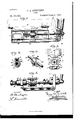
- Figure l represents a partial side elevation and partial vertical section of a vise embodying my invention.
- Fig. 2 represents a segmental vertical section on line 9:
- Fig. 3 represents a perspective view of a detached' portion thereof, the threads on the spindle in said portion being omitted.
- Fig. 1 represents a partial side elevation and partial vertical section of a vise embodying my invention.
- Fig. 2 represents a segmental vertical section on line 9:
- Fig. 3 represents a perspective view of a detached' portion thereof, the threads on the spindle in said portion being omitted.
- i represents a partial end elevation and par-- tial vertical section on line 'y y, Fig. l. Fig.
- A designates a frame of a vise, which is secured in any suitable manner to a work-ben ch B, and provided with a rack C and a guide B', in which latter is fitted a slide L, which is provided at one end with an ear K and has at the other end the jaw P, pivoted thereto.
- a spindle which has screwthreads Il and J at the ends thereof, the threads Il being fitted to the ear K and the other threads J being fitted in a nut M, which latter freely occupies an angular opening N in said jaw, it being noticed that said threads have different pitches.
- a collar D Secured to said spindle G is a collar D, having circumferential teeth E and a longitudinally-extendin g groove F on the circumference, the teeth E thereof engaging with the teeth of the rack C for locking the spindle with the frame of the vise.
- the teeth E are connected at one end by the wall E of the groove F, the same being adapted to abut against the teeth of the rack C, with which the said teeth E engage, thus providing a stop which limits the rotation of the collar D, while the other ends of said teeth E are free to enter the rackteeth when said collar is properlyT rotated.
- the collar D is primarily applied to the rack C, the groove F permitting it to be placed at an adjusted position thereon relative to the comparative size of the article to be held by the vise.
- the article is then located between the jaw and bench, the latter also serving as a jaw.
- the spindle is now turned so that the teeth E engage with those of the rack C as a connection for the spindle with said rack, it being noticed that said collar forms a swivel for the spindle, whereby the latter is permitted to rotate without moving in longitudinal direction.
- cams Q Q' may be employed as shown in Fig. 5.
- the cams Q are secured to the jaw P and the ears K, respectively, and have the spindle G passed freely through the same.
- the cams Q are secured to said spindle so as to rotate therewith, and thus impart motion to said jaws similar to the action of the screw-threads shown in the other figures.
- On the spindle" are also the cams Q2, which are connected with the same by feathers, which permit said cams to slide on the spindle and also to rotate therewith.
- a slide carrying one of the jaws thereof, a frame having a rack, a screw en- IOO gaged with said slide and jaw, and a toothed collar adapted to engage with said rack and form a swivel for said screw, substantially as described.
- a toothed collar engaging with a rack on the frame of the vise, and a screwspindle fitted to one of the jaws of the vise and secured in said collar, the latter having a lon gitudinally-extending groove for the passage of the rack in primarily adjusting the jaw, said parts being combined substantially as described.
- a frame with a rack, and a guide a movable slide in said guide having a pivoted jaw on its end, a spindle mounted on said slide having threads of different pitch, said threads respectively engaging an ear on said frame, and a non-rotatable nut held in the pivoted jaw and a collar secured to said spindle, having peripheral teeth engaging said rack, said parts being combined substantially as described.
- a vise consisting of a frame, provided with a rack and a guide, a slide in said guide, having an ear on one end and a pivoted jaw on the other end, a non-rotatable nut, in an opening in said jaw, a spindle With threads of different pitch, said threads engaging said ear and nut respectively, and a collar secured to said spindle and having peripheral teeth engaging said rack, said collar having a longitudinal groove on its outer face, said parts being combined substantially as described.
- a vise having a slide, a jawpivotally connected with said slide, a screw engaging said slide and jaw, the pitches of said screw being different at said slide and jaw, a rack and a collar adapted to engage with said rack and form a swivel for said screw substantially as described.
- a frame and a slide on said frame in combination with a jaw which is pivoted on said slide, a screw-spindle for said slide and pivotal jaw, and means for forming a swivel connected with said frame for said spindle, the latter having its threads, where-engaging with said jaw and slide, of different pitches, substantially as and for the purpose set forth.
Landscapes
- Engineering & Computer Science (AREA)
- Mechanical Engineering (AREA)
- Gripping Jigs, Holding Jigs, And Positioning Jigs (AREA)
Description
(No Model.)
Gr. A. GUMPHBRT.
VISE.
No. 561,663. Patented June 9, 1896.
\NlTN ESSES:
' UNITED STATES PATENT" Fries;
GEORGE A. GUMPHERT, OF PHILADELPHIA, PENNSYLVANIA, ASSIGNUR OF ONE-HALF TO GEORGE XV. I'I. FAWKES, OF SAME PLACE.
VISE.
SPECIFICATION forming. part of Letters Patent No. 561,663, dated J' une 9, 1896.
Application filed April ll, 1895. Serial No. 545,358. (No modali) To all whom it may concern.-
Be it known that l, GEORGE A. GUMPHERT, a citizen of the United States, residing in the city and county of Philadelphiatate of Pennsylvania, have invented a new and useful Improvement in Vises, which improvement is fully set forth in the following specification and accompanying drawings.
My invention consists of an improvement in vises formed of a jaw pivoted to a slide and a screw with different pitches of threads engagingsaid jaw and slide,togetherwith means for primarily adjusting the jaw, whereby an effective and powerfully-acting vise is produced, as will be hereinafter set forth.
Figure l represents a partial side elevation and partial vertical section of a vise embodying my invention. Fig. 2 represents a segmental vertical section on line 9:, Fig. l. Fig. 3 represents a perspective view of a detached' portion thereof, the threads on the spindle in said portion being omitted. Fig.
i represents a partial end elevation and par-- tial vertical section on line 'y y, Fig. l. Fig.
represents a partial side elevation and partial vertical section of a modification.
Similar letters of reference indicate corresponding parts in the several gures.
Referring to the drawings, A designates a frame of a vise, which is secured in any suitable manner to a work-ben ch B, and provided with a rack C and a guide B', in which latter is fitted a slide L, which is provided at one end with an ear K and has at the other end the jaw P, pivoted thereto.
G designates a spindle which has screwthreads Il and J at the ends thereof, the threads Il being fitted to the ear K and the other threads J being fitted in a nut M, which latter freely occupies an angular opening N in said jaw, it being noticed that said threads have different pitches. Secured to said spindle G is a collar D, having circumferential teeth E and a longitudinally-extendin g groove F on the circumference, the teeth E thereof engaging with the teeth of the rack C for locking the spindle with the frame of the vise.
It will be noticed that the teeth E are connected at one end by the wall E of the groove F, the same being adapted to abut against the teeth of the rack C, with which the said teeth E engage, thus providing a stop which limits the rotation of the collar D, while the other ends of said teeth E are free to enter the rackteeth when said collar is properlyT rotated.
The collar D is primarily applied to the rack C, the groove F permitting it to be placed at an adjusted position thereon relative to the comparative size of the article to be held by the vise. The article is then located between the jaw and bench, the latter also serving as a jaw. The spindle is now turned so that the teeth E engage with those of the rack C as a connection for the spindle with said rack, it being noticed that said collar forms a swivel for the spindle, whereby the latter is permitted to rotate without moving in longitudinal direction. The spindle is then rotated and the ear K advances, and with it the slide Il and j aw P, it being noticed that said jaw P is now closed against the article first by longitudinal 1n otion and then by radial motion, due to the pivotal connection ofthe jaw with the slide and the different pitches of the screws or screw-spindle.
In lieu of the threads on the spindle I may employ cams Q Q', as shown in Fig. 5. The cams Q are secured to the jaw P and the ears K, respectively, and have the spindle G passed freely through the same. 'The cams Q are secured to said spindle so as to rotate therewith, and thus impart motion to said jaws similar to the action of the screw-threads shown in the other figures. On the spindle" are also the cams Q2, which are connected with the same by feathers, which permit said cams to slide on the spindle and also to rotate therewith. Springs R bear against said cams Q2 in order to return the jaw to its normal or upright position, it being evident that when the spindleis turned the cams Q press against the cams Q and thus cause the jaw P to close tightly against the object that is to be gripped, it being also noticed that the pitch of the cams on the right is coarser than that on the left, but the action is similar to that of the screws .I and Il.
Having thus described my invention, what I claim as new, and desire to secure by Letters Patent, is-
l. In a vise, a slide carrying one of the jaws thereof, a frame having a rack, a screw en- IOO gaged with said slide and jaw, and a toothed collar adapted to engage with said rack and form a swivel for said screw, substantially as described.
2. In a vise, a toothed collar engaging with a rack on the frame of the vise, and a screwspindle fitted to one of the jaws of the vise and secured in said collar, the latter having a lon gitudinally-extending groove for the passage of the rack in primarily adjusting the jaw, said parts being combined substantially as described.
3. In a vise, a frame with a rack, and a guide, a movable slide in said guide having a pivoted jaw on its end, a spindle mounted on said slide having threads of different pitch, said threads respectively engaging an ear on said frame, and a non-rotatable nut held in the pivoted jaw and a collar secured to said spindle, having peripheral teeth engaging said rack, said parts being combined substantially as described.
4. A vise consisting of a frame, provided with a rack and a guide, a slide in said guide, having an ear on one end and a pivoted jaw on the other end, a non-rotatable nut, in an opening in said jaw, a spindle With threads of different pitch, said threads engaging said ear and nut respectively, and a collar secured to said spindle and having peripheral teeth engaging said rack, said collar having a longitudinal groove on its outer face, said parts being combined substantially as described.
5. A vise havinga slide, a jawpivotally connected with said slide, a screw engaging said slide and jaw, the pitches of said screw being different at said slide and jaw, a rack and a collar adapted to engage with said rack and form a swivel for said screw substantially as described.
6. A frame and a slide on said frame, in combination with a jaw which is pivoted on said slide, a screw-spindle for said slide and pivotal jaw, and means for forming a swivel connected with said frame for said spindle, the latter having its threads, where-engaging with said jaw and slide, of different pitches, substantially as and for the purpose set forth.
GEORGE A. GUMPHERT.
Vi tnesses:
JOHN A. WIEDERSHEIM, A. P. JENNINGS.
Publications (1)
| Publication Number | Publication Date |
|---|---|
| US561663A true US561663A (en) | 1896-06-09 |
Family
ID=2630384
Family Applications (1)
| Application Number | Title | Priority Date | Filing Date |
|---|---|---|---|
| US561663D Expired - Lifetime US561663A (en) | George a |
Country Status (1)
| Country | Link |
|---|---|
| US (1) | US561663A (en) |
-
0
- US US561663D patent/US561663A/en not_active Expired - Lifetime
Similar Documents
| Publication | Publication Date | Title |
|---|---|---|
| US1039831A (en) | Work-clamp. | |
| US561663A (en) | George a | |
| US1055278A (en) | Quick-acting vise. | |
| US1012226A (en) | Vise. | |
| US595546A (en) | Auick-acting vise | |
| US235469A (en) | Chuck for planing-machines | |
| US690311A (en) | Vise. | |
| US1003060A (en) | Wrench. | |
| US1306020A (en) | Gtrstaf e | |
| US570340A (en) | David c | |
| US616331A (en) | Augustus howard | |
| US1094359A (en) | Bench-vise. | |
| US1125911A (en) | Vise. | |
| US449476A (en) | haire | |
| US1239620A (en) | Vise. | |
| US1349564A (en) | Wrench | |
| US1126064A (en) | Hatch-fastener. | |
| US361777A (en) | Jefferson patten | |
| US423992A (en) | Clamping mechanism | |
| US55109A (en) | Improvement in screw-wrenches | |
| US641457A (en) | Bench-vise. | |
| US1081293A (en) | Die-stock. | |
| US1180451A (en) | Vise. | |
| US77289A (en) | Abiezee jameson | |
| US265639A (en) | Andrew saunders |