US5599164A - Centrifugal process pump with booster impeller - Google Patents
Centrifugal process pump with booster impeller Download PDFInfo
- Publication number
- US5599164A US5599164A US08/415,444 US41544495A US5599164A US 5599164 A US5599164 A US 5599164A US 41544495 A US41544495 A US 41544495A US 5599164 A US5599164 A US 5599164A
- Authority
- US
- United States
- Prior art keywords
- primary
- impeller
- pump
- booster
- shaft
- Prior art date
- Legal status (The legal status is an assumption and is not a legal conclusion. Google has not performed a legal analysis and makes no representation as to the accuracy of the status listed.)
- Expired - Lifetime
Links
- 238000000034 method Methods 0.000 title claims abstract description 23
- 239000007788 liquid Substances 0.000 claims description 18
- 238000005086 pumping Methods 0.000 claims description 16
- 208000028659 discharge Diseases 0.000 abstract description 28
- 239000012530 fluid Substances 0.000 abstract description 24
- 238000011144 upstream manufacturing Methods 0.000 abstract description 2
- 238000007599 discharging Methods 0.000 abstract 2
- 238000012423 maintenance Methods 0.000 description 6
- 239000003208 petroleum Substances 0.000 description 6
- 238000013461 design Methods 0.000 description 5
- 238000010586 diagram Methods 0.000 description 5
- 230000002093 peripheral effect Effects 0.000 description 5
- 238000012986 modification Methods 0.000 description 4
- 230000004048 modification Effects 0.000 description 4
- 238000004891 communication Methods 0.000 description 3
- 230000013011 mating Effects 0.000 description 3
- 125000006850 spacer group Chemical group 0.000 description 3
- 238000010348 incorporation Methods 0.000 description 2
- 238000010276 construction Methods 0.000 description 1
- 230000009977 dual effect Effects 0.000 description 1
- 230000000694 effects Effects 0.000 description 1
- 230000005484 gravity Effects 0.000 description 1
- 239000000411 inducer Substances 0.000 description 1
- 239000000463 material Substances 0.000 description 1
- 238000013021 overheating Methods 0.000 description 1
- 238000007670 refining Methods 0.000 description 1
- 238000007789 sealing Methods 0.000 description 1
- 238000012360 testing method Methods 0.000 description 1
Images


Classifications
-
- F—MECHANICAL ENGINEERING; LIGHTING; HEATING; WEAPONS; BLASTING
- F04—POSITIVE - DISPLACEMENT MACHINES FOR LIQUIDS; PUMPS FOR LIQUIDS OR ELASTIC FLUIDS
- F04D—NON-POSITIVE-DISPLACEMENT PUMPS
- F04D13/00—Pumping installations or systems
- F04D13/12—Combinations of two or more pumps
- F04D13/14—Combinations of two or more pumps the pumps being all of centrifugal type
-
- F—MECHANICAL ENGINEERING; LIGHTING; HEATING; WEAPONS; BLASTING
- F04—POSITIVE - DISPLACEMENT MACHINES FOR LIQUIDS; PUMPS FOR LIQUIDS OR ELASTIC FLUIDS
- F04D—NON-POSITIVE-DISPLACEMENT PUMPS
- F04D1/00—Radial-flow pumps, e.g. centrifugal pumps; Helico-centrifugal pumps
- F04D1/06—Multi-stage pumps
Definitions
- the present invention relates to centrifugal process pumps and more particularly single-stage, overhung-type centrifugal process pumps having a discharge booster impeller.
- Centrifugal process pumps are widely used in the petroleum industry, particularly in refining and petrochemical plants.
- the requirements for these pumps include operating temperatures varying from about ambient to about 800° F., with pressures up to approximately 600 pounds per square inch (psi) and flow rates ranging from approximately 10 gallons per minute (gpm) to approximately 8,000 gpm.
- Pump companies have developed many different types of pumps to fulfill the demands of the petroleum industry.
- the American Petroleum Institute (API) has issued pump specification API Standard 610 (API 610) which outlines basic mechanical, hydraulic and testing requirements for the various types of pumps to satisfy the demands of the petroleum industry.
- API 610 API Standard 610
- the API specification is very stringent with regards to centrifugal process pumps for use in the petroleum industry due to the obvious safety precautions.
- Centrifugal pumps are also widely used in industries other than the petroleum industry. Pump specifications other than API are usually used in other industries. One such specification is the specification of American National Standards Institute (ANSI).
- ANSI American National Standards Institute
- the present invention involves the use of a booster impeller with a centrifugal pump.
- boost in pumping systems is used in different ways.
- a “booster pump” is sometimes used to refer to a separate pump on the suction/inlet side of a primary pump to increase the net positive suction head (NPSH) to the primary pump.
- NPSH net positive suction head
- the NPSH is an analysis of energy conditions on the suction side of a pump to determine if the liquid will vaporize at the lowest pressure point in the pump.
- One such booster pump system is disclosed in U.S. Pat. No. 3,299,815 to Thaw.
- a "suction booster device", such as an inducer, incorporated as part of the primary pump to improve its NPSH is also called a booster. Examples of this are disclosed in U.S. Pat. No. 3,004,494 to Corbett and U.S. Pat. No. 4,067,665 to Schwartzman.
- a secondary pump (or another impeller) downstream of and in series with the primary pump (or primary impeller) to increase discharge pressure is also called a booster.
- An example of this is disclosed in U.S. Pat. No. 4,209,282 to Eberhardt.
- a pump may be classified as a single-stage (one impeller pumping all the fluid) or as a multi-stage (two or more impellers all pumping the same flow of fluid).
- Overhung pumps are characterized by impellers mounted on a shaft cantilevered from a bearing bracket or mounted on an extended motor shaft where the motor bearings also serve as pump bearings.
- Overhung pumps may be single or two-stage, may use single or double-suction impellers, and may be mounted with shafts horizontal or vertical.
- a single-suction impeller has an inlet on one side and a double-suction impeller has inlets on both sides of the impeller.
- Bearings are generally anti-friction (ball) type.
- overhung pumps Due to the cantilevered shaft, overhung pumps are typically small (5 to 800 horsepower), discharge pressure of 30 to 600 psi, and generally operate at 1800 or 3600 rpm.
- the maximum impeller diameter for an overhung pump operating at 3600 rpm is approximately 13 to 15 inches and for an overhung pump operating at 1800 rpm is approximately 23 inches.
- Between bearing pumps are characterized by impellers mounted on a shaft supported by bearings on both sides of the impellers. They may be single-stage (usually with double-suction impellers) or multi-stage, with bearings either anti-friction (for smaller sizes) or sleeve-type for larger sizes and/or high speed (greater than 3600 rpm) applications. This type of pump is typically used where flows and/or pressures exceed accepted limits for the less expensive overhung type.
- overhung pumps are typically more desirable than between bearing pumps because they are less expensive and require only one mechanical seal versus two mechanical seals for a between bearing pump.
- the between bearing pump may cost approximately 1.5 to 2 times more than the comparable overhung pump.
- API 610 is more stringent than the more general purpose pump specifications of ANSI.
- an API 610 pump may cost on the order of approximately twice that of the same size ANSI pump.
- a multistage pump is a pump using two or more impellers operating in series with each impeller pumping the same flow. If a two-stage pump (multi-stage pump having two impellers each pumping the same flow) is required in an application having to comply with API 610, the more expensive, between bearing pump must be used instead of the overhung pump.
- Pump shaft deflection is affected by various factors including the length and diameter of the cantilevered shaft portion and the diameter of the pump impeller mounted on the cantilevered shaft portion.
- Some pumping systems require pumping a fluid from a single source to two or more different destinations having different head-capacity requirements. This pumping system requires compromises when one head-capacity requirement is a high pressure (head) at low flow (capacity) and the second head-capacity requirement is a lower pressure (head) at higher flow (capacity).
- Pump efficiency is defined as the ratio of the hydraulic horsepower to the brake horsepower. Hydraulic horsepower (whp) or pump output is the liquid horsepower delivered by the pump. Brake horsepower (bhp) or pump input is the actual horsepower delivered to the pump shaft. The brake horsepower is always greater than the hydraulic horsepower of a pump due to the mechanical and hydraulic losses incurred in the pump.
- destination "A” requires a high head at a low flow and destination "B” requires a lower head at a higher flow.
- One solution may be to have a separate centrifugal process pump for each destination "A" and "B.” This may not be the optimum solution due to the increased maintenance and costs required for two process pumps and the motors to operate these two pumps.
- Another solution may be to use one oversized centrifugal process pump to pump fluids from a single source to destinations "A" and "B” with a throttling valve.
- a typical pump selected must have the pump head-capacity characteristic curve to envelop the requirements of destinations "A” and "B.”
- the pump head-capacity characteristic curve cannot envelop the high head/low flow requirement of destination "A” without producing excess head at the low head/high flow requirement of destination "B.” This results in an inefficient pumping system due to the divergent head-capacity requirements of the dual destinations.
- a pump When the pump's head-capacity curve must envelop such different rating points (i.e., low head at high flow and high head at low flow), a pump is selected which will be larger and more costly than a pump having to envelop one set of head-capacity requirements.
- a larger pump requires more horsepower delivered to the pump shaft which in turn requires a larger horsepower motor which is more expensive to purchase and operate.
- the required throttling valve also results in additional cost and maintenance. Such a solution is inefficient and costly.
- U.S. Pat. No. 4,209,282 to Eberhardt discloses a pump assembly having a primary pump and a booster pump driven from a common rotating shaft.
- the primary pump delivers low head at high flow fluid and the booster pump delivers high head at low flow fluid.
- the two-stage, overhung, high head, low flow booster pump takes suction from a single-stage, double suction impeller, overhung primary pump.
- the impellers of the booster pump and the impeller of the primary pump are in separate pump cases and mounted on a common shaft with geared power input to the shaft between the pump cases.
- the Eberhardt booster pump incorporates a bypass from the booster pump discharge to the primary pump suction (to protect the booster pump from damage if dead-headed).
- the Eberhardt booster pump is a single casing type with a maximum discharge pressure of approximately 400 psi from the booster pump.
- the Eberhardt pump assembly is two pumps powered from a single prime mover. Thus, from a maintenance standpoint, the Eberhardt pump assembly may require additional maintenance over a single pump servicing both destinations.
- the centrifugal process pump with booster impeller and method enables the pump to produce its normal rated head-capacity flow stream and additionally, produce a separate higher-head, low-capacity flow stream.
- the centrifugal process pump with booster impeller is effectively two pumps in one, and saves input energy and control valve losses in cases where a single pump is used to satisfy the head-capacity requirements of two different flow streams.
- the centrifugal pump assembly with booster impeller is an overhung pump with a single-stage primary impeller and a single-stage booster impeller taking suction from the discharge of the primary impeller.
- the primary impeller produces a low head at high capacity flow stream and the booster impeller produces a higher head at lower capacity flow stream.
- the primary and booster impellers are substantially adjacently mounted on a cantilevered portion of a pump shaft.
- the centrifugal pump assembly with booster impeller is effectively two pumps in one casing with the pump assembly having a common suction and two separate discharges. It is not classified as a two-stage pump because the primary and booster impellers do not pump the same flow (i.e., all flow from primary impeller does not flow through booster impeller).
- the booster impeller is incorporated into the same pump case assembly as the primary impeller and increases the shaft cantilever by approximately 20% as compared with approximately 100% for a second stage impeller of a conventional two-stage overhung pump.
- centrifugal pump assembly with booster impeller results in energy savings by utilizing a more efficient hydraulic configuration which thereby allows use of a lower horsepower prime mover (motor).
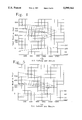
- FIG. 1 is a sectional view in elevation of the centrifugal pump assembly according to a first embodiment of the present invention, the centrifugal pump assembly shown as an overhung, horizontal, single-stage, end suction pump with a booster impeller;
- FIG. 2 is a sectional view in elevation of the centrifugal pump assembly according to a second embodiment of the present invention, the centrifugal pump assembly shown as an overhung, in-line, single-stage pump with a booster impeller;
- FIG. 3 is a sectional view taken along lines 3--3 of FIG. 1;
- FIG. 4 is a diagram showing typical pump performance curves for a conventional 4 inch, single stage, overhung pump for three sizes of impellers;
- FIG. 5 is a diagram showing typical pump performance curves for a conventional 4 inch, single stage, overhung pump for three sizes of impellers and including a performance curve for a booster impeller;
- FIG. 6 is a diagram showing typical pump performance curves for a conventional 3 inch, single stage, overhung pump for three sizes of impellers;
- FIG. 7 is a diagram showing typical pump performance curves for a conventional 3 inch, single stage, overhung pump for three sizes of impellers and including a performance curve for a booster impeller;
- FIG. 8 is a diagram comparing pump performance curves and illustrating the advantages of the present invention over conventional process pumps.
- FIG. 1 discloses the centrifugal pump assembly according to a first embodiment of the present invention in which the centrifugal pump assembly is shown as an overhung, horizontal, single-stage, end suction, top discharge pump with a booster impeller. Although not shown, it is within the scope of the present invention that the centrifugal pump assembly disclosed in FIG. 1 could alternatively be a top suction as opposed to the end suction type as shown.
- FIG. 2 discloses the centrifugal pump assembly according to a second embodiment of the present invention in which the centrifugal pump assembly is shown as an overhung, vertical in-line, single-stage pump with a booster impeller.
- centrifugal pump assembly according to the first embodiment is referred to generally as 10 and the centrifugal pump assembly according to the second embodiment is referred to generally as 100.
- Like reference numbers will be used to indicate like components of the two embodiments.
- centrifugal pump assembly 10 is a modification to existing overhung, horizontal, single-stage process pumps commonly available from a variety of pump manufacturers such as BW/IP International, Inc., Long Beach, Calif., Goulds Pumps, Inc., Seneca Falls, N.Y., and Sulzer-Bingham, Portland, Oreg.
- the centrifugal pump assembly 100 is a modification to existing overhung, in-line, single-stage process pumps commonly available from a variety of pump manufacturers such as those named above.
- centrifugal pump assembly 10, 100 The primary focus of the following detailed discussion of the centrifugal pump assembly 10, 100 will be with respect to the modification comprising the invention.
- the modification is primarily at the impeller end of the centrifugal pump assembly 10, 100 as will be explained below.
- the "unchanged" portion of the prior art process pumps will be only generally discussed as the unchanged portion is commonly known to one of ordinary skill in the art.
- the centrifugal pump assembly 10, 100 includes a pump housing assembly 11 comprising a pump case 12, a pump case cover 13 and a bearing bracket 32.
- the pump housing assembly 11 has a primary inlet 14 and a primary discharge 16.
- the primary inlet 14 includes an inlet passageway 18 which communicates at its downstream end with the entrance 22 of the single-stage, single suction primary impeller 20 as shown in FIGS. 1 and 2.
- the primary impeller 20 has an exit 24 communicating with the primary discharge 16.
- the primary impeller 20 is mounted on a cantilevered portion 28 of a shaft 26.
- the shaft 26 in the horizontal single stage pump with booster impeller of FIG. 1 is in a horizontal position whereas the shaft 26 in the in-line single stage pump with booster impeller of FIG. 2 is in a vertical position.
- the shaft 26 includes a second end 30 (FIG. 1) opposite the cantilevered portion 28 which is adapted to be connected to a power means such as a motor (not shown) for rotating the shaft 26.
- a power means such as a motor (not shown) for rotating the shaft 26.
- the shaft 26 could be the motor shaft with the primary impeller 20 mounted thereon as shown in FIG. 2.
- the primary impeller 20 is secured on the shaft 26 with a primary impeller key (not shown) received in an elongated slot (not shown) in the shaft 26.
- a booster impeller 36 is also mounted on the cantilevered portion 28 of the shaft 26.
- the booster impeller 36 is secured on the shaft 26 with a booster impeller key (not shown) received in the elongated slot (not shown) in the shaft 26.
- the booster impeller 36 is positioned on the shaft 26 between the primary impeller 20 and the bearings 34.
- the booster impeller 36 is preferably located substantially adjacent to the primary impeller 20 to minimize the overall length of the cantilevered portion 28 of the shaft 26.
- the shaft 26 is supported by the bearing bracket 32.
- the bearing bracket 32 includes an outboard bearing 34 and an inboard bearing 34' to rotatably support the shaft 26.
- a seal means 52 typically a mechanical seal, surrounds the shaft 26 between the inboard bearing 34' and the booster impeller 36. Mechanical seals are well known in the art. The type of mechanical seal 52 may vary. The mechanical seal prevents undesirable leakage of fluid to atmosphere. In an overhung-type pump only one mechanical seal is required. In a between bearing pump two mechanical seals are required.
- conduit means 42 are provided for diverting some of the fluid flow from the primary discharge 16 to a secondary inlet or booster inlet 38.
- the conduit means 42 comprises tubing or piping. It is to be understood that fluid could alternatively be introduced to the secondary or booster inlet 38 without passing through the primary impeller 20, as for example, by diverting some of the fluid flow upstream of the centrifugal process pump 10, 100 or the primary impeller 20 directly to the booster inlet 38.
- the booster inlet 38 includes a booster inlet passageway 40 which communicates at its downstream end with the booster impeller entrance 44 of the single suction booster impeller 36 as shown in FIGS. 1-3.
- the booster impeller 36 has an exit 46 communicating with a secondary discharge or booster discharge 48.
- the primary and booster impellers 20 and 36 are both mounted on the cantilevered portion 28 of the pump shaft 26.
- the booster impeller 36 rotates at the same speed as the primary impeller 20.
- the booster impeller 36 is a drilled hole type impeller (see FIG. 3). It is to be understood that the booster impeller 36 is not limited to a drilled hole type impeller and that other types of impellers may be used as the booster impeller 36.
- the drilled hole type booster impeller 36 includes a circular disc 54 having a central longitudinal bore 56 therethrough and a plurality of fluid bores 58 extending from an outer peripheral surface 60 to the central longitudinal bore 56.
- the fluid bores 58 are in communication with the booster impeller entrance 44 as shown in FIGS. 1-3.
- the fluid bores 58 as shown in FIG. 3 are radial bores. It is to be understood that the fluid bores 58 are not limited to radial bores but may have other configurations and orientations in providing communication between the outer peripheral surface 60 and the central longitudinal bore 56.
- the booster impeller 36 in the preferred embodiment as shown in FIGS. 1-3 includes a peripheral shoulder 62 extending from the circular disc 54.
- a first spacer sleeve 63 is mounted on the shaft 26 between the booster impeller 36 and the mechanical seal 52.
- the booster impeller entrance 44 is defined by the annular spacing between the peripheral shoulder 62 and the first spacer sleeve 63.
- an impeller hub 64 Opposite the peripheral shoulder 62 is an impeller hub 64 which is secured to the shaft 26.
- an intermediate cover 66 is positioned between the primary impeller 20 and the booster impeller 36.
- the intermediate cover 66 is non-rotatably secured to the pump case assembly 12.
- the intermediate cover 66 includes a first interior annular recess 68 and a second interior annular recess 70.
- the annular recesses 68 and 70 receive stationary wear rings 69 and 71, respectively.
- a mating rotating wear ring 69' is installed on a neck 72 of the primary impeller 20 and a mating rotating wear ring 71' is installed on the impeller hub 64 of the booster impeller 36.
- the pair of wear rings 69 and 69' rotatably mate with each other and the pair of wear rings 71 and 71' rotatably mate with each other.
- Each pair of wear rings permit controlled leakage of fluid therebetween.
- Wear rings are well known in the art.
- a second spacer sleeve 74 is mounted on the shaft 26 between the primary impeller 20 and the booster impeller 36.
- Balance holes 76 extend through a rear shroud 78 of the primary impeller to the entrance 22.
- the balance hole or holes 76 permit fluid communication between the entrance or suction of the primary impeller 20 and the fluid passing between the pairs of wear rings 69, 69' and 71, 71'.
- the booster impeller 36 is "dead-headed" (i.e., no flow through the booster impeller) as for example by closing off the booster discharge 48, the controlled leakage through the pair of mating wear rings 71, 71' and the balance holes 76 to the suction of the primary impeller 20 prevents "dead-heading" damage caused from overheating.
- the booster impeller discharge 48 may be run dead-headed providing the primary impeller is protected in accordance with its minimum flow criteria.
- the booster impeller entrance 44 faces opposite the primary impeller 20 as shown in FIGS. 1 and 2. This shortens the length of the cantilevered portion 28 of the shaft 26 and also reduces the sealing pressure requirement of the mechanical seal 52 to that of the primary discharge pressure as opposed to the higher booster discharge pressure.
- the diameter of the booster impeller 36 is approximately the same diameter as the primary impeller 20.
- the diameter of an impeller has a direct effect on the head produced.
- the booster impeller 36 will have a diameter approximately the same as the primary impeller 20 to optimize the design. It is to be understood, however, that this does not have to be the case and that the booster impeller 36 may have a larger or smaller diameter than the primary impeller 20.
- the primary discharge 16 is a high flow, low head discharge and the booster discharge 48 is a lower flow, higher head discharge.
- the centrifugal pump assembly with booster impeller 10, 100 is effectively two pumps in one pump case/cover assembly 12, 13 with the pump assembly 10, 100 having a common suction 18 and two separate discharges 16 and 48. It is not classified as a two-stage pump because the primary and booster impellers 20 and 36, respectively, do not pump the same flow (i.e., all flow from primary impeller 20 does not flow through booster impeller 36).
- the booster impeller 36 is incorporated into the same pump case/cover assembly 12, 13 as the primary impeller 20 and increases the shaft cantilever 28 by only approximately 20% as compared with approximately 100% for the second stage impeller of a conventional two-stage overhung pump.
- ALTERNATE The performance of a 4 inch pump with a 9.0 inch diameter primary impeller and a low-flow booster impeller is illustrated in FIG. 5.
- the diameter of the booster impeller is 9.0 inches. This pump requires a 60 hp motor.
- the power savings for this example is as follows:
- ALTERNATE The performance of a 3-inch pump with a 11.66-inch diameter impeller and a low-flow booster impeller is illustrated by FIG. 7. This pump uses a 100 hp motor.
- the power savings for this example is as follows:
- FIG. 8 illustrates the significant advantages of the present invention using example 2 above.
- the cross-hatched area shows the head-capacity produced but not required by the process by the conventional 3-inch single-stage, overhung-type pump with a 14.85-inch diameter impeller and a 200 hp motor.
- the use of the 3-inch pump with a 11.66-inch diameter impeller and a low-flow booster impeller according to the present invention with a 100 hp motor saves the brake horsepower required to produce the unneeded capability (cross-hatched area) and the downstream throttling required to satisfy the lower head requirement of destination "B.”
Landscapes
- Engineering & Computer Science (AREA)
- Mechanical Engineering (AREA)
- General Engineering & Computer Science (AREA)
- Structures Of Non-Positive Displacement Pumps (AREA)
Priority Applications (3)
| Application Number | Priority Date | Filing Date | Title |
|---|---|---|---|
| US08/415,444 US5599164A (en) | 1995-04-03 | 1995-04-03 | Centrifugal process pump with booster impeller |
| PCT/US1996/004654 WO1996031703A1 (fr) | 1995-04-03 | 1996-04-03 | Pompe centrifuge pour operations chimiques avec roue de pompe auxiliaire |
| AU53856/96A AU5385696A (en) | 1995-04-03 | 1996-04-03 | Centrifugal process pump with booster impeller |
Applications Claiming Priority (1)
| Application Number | Priority Date | Filing Date | Title |
|---|---|---|---|
| US08/415,444 US5599164A (en) | 1995-04-03 | 1995-04-03 | Centrifugal process pump with booster impeller |
Publications (1)
| Publication Number | Publication Date |
|---|---|
| US5599164A true US5599164A (en) | 1997-02-04 |
Family
ID=23645711
Family Applications (1)
| Application Number | Title | Priority Date | Filing Date |
|---|---|---|---|
| US08/415,444 Expired - Lifetime US5599164A (en) | 1995-04-03 | 1995-04-03 | Centrifugal process pump with booster impeller |
Country Status (3)
| Country | Link |
|---|---|
| US (1) | US5599164A (fr) |
| AU (1) | AU5385696A (fr) |
| WO (1) | WO1996031703A1 (fr) |
Cited By (33)
| Publication number | Priority date | Publication date | Assignee | Title |
|---|---|---|---|---|
| US5993674A (en) * | 1998-02-24 | 1999-11-30 | Membrex, Inc. | Rotary disc filtration device with means to reduce axial forces |
| US6053702A (en) * | 1998-07-15 | 2000-04-25 | Sears; Samuel D. | Portable water pump having a pressure control circuit with a bypass conduit |
| WO2001016491A1 (fr) | 1999-09-01 | 2001-03-08 | Coltec Industries, Inc. | Pompe centrifuge |
| WO2001055601A1 (fr) * | 2000-01-26 | 2001-08-02 | The Gorman-Rupp Company | Pompe centrifuge a plusieurs orifices d'admission |
| US20040062647A1 (en) * | 2002-09-26 | 2004-04-01 | Garrett Norman H. | Roto-dynamic fluidic systems |
| US20040206171A1 (en) * | 2003-04-21 | 2004-10-21 | Feierabend Jerry Glynn | Material testing system for turbines |
| US20050013689A1 (en) * | 2000-01-26 | 2005-01-20 | The Gorman-Rupp Company | Centrifugal pump with multiple inlets |
| US20060024174A1 (en) * | 2004-07-28 | 2006-02-02 | Welch C E | Pump |
| US20060029491A1 (en) * | 2002-09-26 | 2006-02-09 | Garrett Norman H Iii | Roto-dynamic fluidic systems |
| US20060051215A1 (en) * | 2004-09-08 | 2006-03-09 | Knobloch Arthur R | Residential water pressure booster |
| WO2007103248A3 (fr) * | 2006-03-03 | 2008-02-21 | Dresser Rand Co | Dispositif de traitement de fluide multiphase |
| US20110002769A1 (en) * | 2009-07-02 | 2011-01-06 | David Douglas Dieziger | Centrifugal pump for de-watering |
| US7946810B2 (en) | 2006-10-10 | 2011-05-24 | Grundfos Pumps Corporation | Multistage pump assembly |
| US8172523B2 (en) | 2006-10-10 | 2012-05-08 | Grudfos Pumps Corporation | Multistage pump assembly having removable cartridge |
| KR101157432B1 (ko) * | 2011-11-17 | 2012-06-22 | 한국기계연구원 | 이산화탄소 지중 저장용 복합 펌프 |
| US20130183137A1 (en) * | 2011-12-22 | 2013-07-18 | William E. Murray | Centrifugal pump with secondary impeller and dual outlets |
| US20140093357A1 (en) * | 2011-05-19 | 2014-04-03 | Nuovo Pignone S.P.A. | Gas turbine system and corresponding method for assembling |
| WO2014078236A1 (fr) * | 2012-11-13 | 2014-05-22 | Tucson Embedded Systems, Inc. | Système de pompe pour applications à haute pression |
| CN105448367A (zh) * | 2014-08-19 | 2016-03-30 | 中国广核集团有限公司 | 核电站主泵泄漏异常的处理方法 |
| US20180001123A1 (en) * | 2015-07-15 | 2018-01-04 | Kevin Ralph Younker | Fluid system with a continuously variable transmission |
| US9909593B2 (en) | 2009-07-02 | 2018-03-06 | Helen Irene Dieziger | Centrifugal pump for de-watering |
| US20180128272A1 (en) * | 2016-11-10 | 2018-05-10 | Wayne/Scott Fetzer Company | Dual inlet volute, impeller and pump housing for same, and related methods |
| WO2020030373A1 (fr) * | 2018-08-07 | 2020-02-13 | Cryostar Sas | Turbomachine à étages multiples |
| US10907638B2 (en) | 2015-07-27 | 2021-02-02 | Wayne/Scott Fetzer Company | Multi-outlet utility pump |
| USD910719S1 (en) | 2018-07-12 | 2021-02-16 | Wayne/Scott Fetzer Company | Pump components |
| USD914060S1 (en) | 2015-12-17 | 2021-03-23 | Wayne/Scott Fetzer Company | Pump portion |
| US11078902B2 (en) * | 2017-08-16 | 2021-08-03 | Parker-Hannifin Corporation | Adapter plate with heat exchanger for a pump and motor |
| USD942512S1 (en) | 2020-09-29 | 2022-02-01 | Wayne/Scott Fetzer Company | Pump part |
| US11326608B2 (en) | 2017-08-14 | 2022-05-10 | Wayne/Scott Fetzer Company | Thermally controlled utility pump and methods relating to same |
| US20220333487A1 (en) * | 2021-04-20 | 2022-10-20 | Saudi Arabian Oil Company | Integrated power pump |
| US11592033B2 (en) | 2019-09-30 | 2023-02-28 | Wayne/Scott Fetzer Company | Pump assembly and related methods |
| USD982614S1 (en) | 2017-04-05 | 2023-04-04 | Wayne/Scott Fetzer Company | Pump component |
| USD986287S1 (en) | 2017-04-05 | 2023-05-16 | Wayne/Scott Fetzer Company | Pump component |
Citations (30)
| Publication number | Priority date | Publication date | Assignee | Title |
|---|---|---|---|---|
| US825964A (en) * | 1905-01-09 | 1906-07-17 | Charles H Godfrey | Fire-extinguishing system. |
| US1049894A (en) * | 1909-04-17 | 1913-01-07 | Gen Electric | Pumping system. |
| US1076462A (en) * | 1912-03-13 | 1913-10-21 | Gen Electric | Pump for elastic fluids. |
| US1737870A (en) * | 1924-06-05 | 1929-12-03 | Archibald S Telfer | Pump |
| US1988875A (en) * | 1934-03-19 | 1935-01-22 | Saborio Carlos | Wet vacuum pump and rotor therefor |
| US2280626A (en) * | 1940-11-02 | 1942-04-21 | Fred A Carpenter | High-low pressure pumping system |
| US2553066A (en) * | 1944-06-30 | 1951-05-15 | Southern John | Self-priming centrifugal pump |
| US2828066A (en) * | 1954-07-05 | 1958-03-25 | Sulzer Ag | Turbocompressor plant |
| US2833525A (en) * | 1952-12-15 | 1958-05-06 | Mather & Platt Ltd | Centrifugal pumps |
| US2918975A (en) * | 1958-01-22 | 1959-12-29 | F E Myers & Bro Co | Apparatus for pumping liquids |
| US3004494A (en) * | 1957-11-14 | 1961-10-17 | Thompson Ramo Wooldridge Inc | Turbine driven pump inducer |
| US3063673A (en) * | 1958-10-20 | 1962-11-13 | Caterpillar Tractor Co | Centripetal turbine |
| US3107625A (en) * | 1961-09-01 | 1963-10-22 | Walter E Amberg | Centrifugal liquid pump |
| US3115097A (en) * | 1960-08-03 | 1963-12-24 | Wilfley & Sons Inc A | Corrosion resistant centrifugal pump |
| US3118386A (en) * | 1964-01-21 | Multi-stage centrifugal pump | ||
| US3213798A (en) * | 1964-03-16 | 1965-10-26 | Ingersoll Rand Co | Sealing and cooling device for a pump shaft |
| US3299815A (en) * | 1965-06-17 | 1967-01-24 | Worthington Corp | Multistage, turbine driven booster pump system |
| US3542496A (en) * | 1968-06-19 | 1970-11-24 | Maytag Co | Dishwasher pump |
| US3647314A (en) * | 1970-04-08 | 1972-03-07 | Gen Electric | Centrifugal pump |
| US3656861A (en) * | 1970-04-15 | 1972-04-18 | Wilfley & Sons Inc A | Centrifugal pump with mating case plate volute halves and constant section impeller |
| US3707336A (en) * | 1970-11-27 | 1972-12-26 | Hollymatic Corp | Fluid engine |
| US3708241A (en) * | 1971-08-09 | 1973-01-02 | Hollymatic Corp | Fluid engine |
| US4029431A (en) * | 1974-08-23 | 1977-06-14 | Herbert Bachl | Fluid-flow machine |
| US4067665A (en) * | 1975-06-16 | 1978-01-10 | Schwartzman Everett H | Turbine booster pump system |
| US4195965A (en) * | 1977-03-18 | 1980-04-01 | Walter Masnik | Ram pump flowmeter |
| US4208282A (en) * | 1978-03-01 | 1980-06-17 | Becker Dieter J | Process for the purification of sewage while recapturing the fatty and albuminous matter in reusable form |
| US4293278A (en) * | 1978-05-16 | 1981-10-06 | Getewent Gesellschaft Fur Technische Und Wissenschaftlichs Energieumsatzentwicklungen M.B.H. | Fluid-flow machine |
| GB2135022A (en) * | 1983-02-14 | 1984-08-22 | Stephen Walker Tebby | Improvements in or relating to impeller pumps particularly for fire fighting |
| US4734019A (en) * | 1986-12-05 | 1988-03-29 | Hale Fire Pump Company | Pumping system |
| US4779575A (en) * | 1987-08-04 | 1988-10-25 | Perkins Eugene W | Liquid friction heating apparatus |
-
1995
- 1995-04-03 US US08/415,444 patent/US5599164A/en not_active Expired - Lifetime
-
1996
- 1996-04-03 WO PCT/US1996/004654 patent/WO1996031703A1/fr active Application Filing
- 1996-04-03 AU AU53856/96A patent/AU5385696A/en not_active Abandoned
Patent Citations (30)
| Publication number | Priority date | Publication date | Assignee | Title |
|---|---|---|---|---|
| US3118386A (en) * | 1964-01-21 | Multi-stage centrifugal pump | ||
| US825964A (en) * | 1905-01-09 | 1906-07-17 | Charles H Godfrey | Fire-extinguishing system. |
| US1049894A (en) * | 1909-04-17 | 1913-01-07 | Gen Electric | Pumping system. |
| US1076462A (en) * | 1912-03-13 | 1913-10-21 | Gen Electric | Pump for elastic fluids. |
| US1737870A (en) * | 1924-06-05 | 1929-12-03 | Archibald S Telfer | Pump |
| US1988875A (en) * | 1934-03-19 | 1935-01-22 | Saborio Carlos | Wet vacuum pump and rotor therefor |
| US2280626A (en) * | 1940-11-02 | 1942-04-21 | Fred A Carpenter | High-low pressure pumping system |
| US2553066A (en) * | 1944-06-30 | 1951-05-15 | Southern John | Self-priming centrifugal pump |
| US2833525A (en) * | 1952-12-15 | 1958-05-06 | Mather & Platt Ltd | Centrifugal pumps |
| US2828066A (en) * | 1954-07-05 | 1958-03-25 | Sulzer Ag | Turbocompressor plant |
| US3004494A (en) * | 1957-11-14 | 1961-10-17 | Thompson Ramo Wooldridge Inc | Turbine driven pump inducer |
| US2918975A (en) * | 1958-01-22 | 1959-12-29 | F E Myers & Bro Co | Apparatus for pumping liquids |
| US3063673A (en) * | 1958-10-20 | 1962-11-13 | Caterpillar Tractor Co | Centripetal turbine |
| US3115097A (en) * | 1960-08-03 | 1963-12-24 | Wilfley & Sons Inc A | Corrosion resistant centrifugal pump |
| US3107625A (en) * | 1961-09-01 | 1963-10-22 | Walter E Amberg | Centrifugal liquid pump |
| US3213798A (en) * | 1964-03-16 | 1965-10-26 | Ingersoll Rand Co | Sealing and cooling device for a pump shaft |
| US3299815A (en) * | 1965-06-17 | 1967-01-24 | Worthington Corp | Multistage, turbine driven booster pump system |
| US3542496A (en) * | 1968-06-19 | 1970-11-24 | Maytag Co | Dishwasher pump |
| US3647314A (en) * | 1970-04-08 | 1972-03-07 | Gen Electric | Centrifugal pump |
| US3656861A (en) * | 1970-04-15 | 1972-04-18 | Wilfley & Sons Inc A | Centrifugal pump with mating case plate volute halves and constant section impeller |
| US3707336A (en) * | 1970-11-27 | 1972-12-26 | Hollymatic Corp | Fluid engine |
| US3708241A (en) * | 1971-08-09 | 1973-01-02 | Hollymatic Corp | Fluid engine |
| US4029431A (en) * | 1974-08-23 | 1977-06-14 | Herbert Bachl | Fluid-flow machine |
| US4067665A (en) * | 1975-06-16 | 1978-01-10 | Schwartzman Everett H | Turbine booster pump system |
| US4195965A (en) * | 1977-03-18 | 1980-04-01 | Walter Masnik | Ram pump flowmeter |
| US4208282A (en) * | 1978-03-01 | 1980-06-17 | Becker Dieter J | Process for the purification of sewage while recapturing the fatty and albuminous matter in reusable form |
| US4293278A (en) * | 1978-05-16 | 1981-10-06 | Getewent Gesellschaft Fur Technische Und Wissenschaftlichs Energieumsatzentwicklungen M.B.H. | Fluid-flow machine |
| GB2135022A (en) * | 1983-02-14 | 1984-08-22 | Stephen Walker Tebby | Improvements in or relating to impeller pumps particularly for fire fighting |
| US4734019A (en) * | 1986-12-05 | 1988-03-29 | Hale Fire Pump Company | Pumping system |
| US4779575A (en) * | 1987-08-04 | 1988-10-25 | Perkins Eugene W | Liquid friction heating apparatus |
Non-Patent Citations (18)
| Title |
|---|
| BW/IP International, Inc., Preliminary Selection Range Chart Double Case Type HDB Feed Pump and Single Stage Process Pumps Range Chart Drawings, Jun. 1978, 2 pages. * |
| BW/IP International, Inc., Single Stage Process Pumps Type SC7, Sep. 1991, 1 page. * |
| BW/IP International, Inc., Single Stage Process Pumps--Type SC7, Sep. 1991, 1 page. |
| BW/IP International, Inc., Two Stage Process Pump Type GSJH, Mar. 1983, 1 page. * |
| BW/IP International, Inc., Two Stage Process Pumps Type GSJA Drawing, Mar. 1983, 1 page. * |
| BW/IP International, Inc., Two Stage Process Pumps--Type GSJA Drawing, Mar. 1983, 1 page. |
| BW/IP International, Inc., Two Stage Process Pump--Type GSJH, Mar. 1983, 1 page. |
| BW/IP, Byron Jackson Submersibles Brochure, Sep. 1989, 6 pages. * |
| Byron Jackson Pump Division Borg Warner Corporation, 4 Stage Type HDB Byron Jackson Boiler Feed Pump Drawing, Jun. 1978, 1 page. * |
| Byron Jackson Pump Division Borg Warner Corporation, High Pressure Double Case Type HDB & HSB Feed Pumps Booster Stage Take Off (Optional) Drawing, Jun. 1978, 1 page. * |
| Byron Jackson Pump Division--Borg Warner Corporation, 4 Stage-Type HDB Byron Jackson Boiler Feed Pump Drawing, Jun. 1978, 1 page. |
| Byron Jackson Pump Division--Borg Warner Corporation, High Pressure-Double Case-Type HDB & HSB Feed Pumps Booster Stage Take-Off (Optional) Drawing, Jun. 1978, 1 page. |
| Goulds Pumps, Inc., GPM Goulds Pump Manual (Fifth Edition), 1988, pp. 6A 6B. * |
| Goulds Pumps, Inc., GPM Goulds Pump Manual (Fifth Edition), 1988, pp. 6A-6B. |
| Tyler G. Hicks, P. E. and T. W. Edwards, P. E., Pump Application Engineering Book, 1971, pp. 305 306. * |
| Tyler G. Hicks, P. E. and T. W. Edwards, P. E., Pump Application Engineering--Book, 1971, pp. 305-306. |
| Val S. Lobanoff and Robert R. Ross, Centrifugal Pumps Design and Application Book, 1985, pp. 197 199, 202, 204, 207 and 216. * |
| Val S. Lobanoff and Robert R. Ross, Centrifugal Pumps--Design and Application--Book, 1985, pp. 197-199, 202, 204, 207 and 216. |
Cited By (56)
| Publication number | Priority date | Publication date | Assignee | Title |
|---|---|---|---|---|
| US5993674A (en) * | 1998-02-24 | 1999-11-30 | Membrex, Inc. | Rotary disc filtration device with means to reduce axial forces |
| US6053702A (en) * | 1998-07-15 | 2000-04-25 | Sears; Samuel D. | Portable water pump having a pressure control circuit with a bypass conduit |
| US6361270B1 (en) | 1999-09-01 | 2002-03-26 | Coltec Industries, Inc. | Centrifugal pump for a gas turbine engine |
| WO2001016491A1 (fr) | 1999-09-01 | 2001-03-08 | Coltec Industries, Inc. | Pompe centrifuge |
| US6799943B2 (en) | 2000-01-26 | 2004-10-05 | The Gorman-Rupp Company | Centrifugal pump with multiple inlets |
| US20050013689A1 (en) * | 2000-01-26 | 2005-01-20 | The Gorman-Rupp Company | Centrifugal pump with multiple inlets |
| WO2001055601A1 (fr) * | 2000-01-26 | 2001-08-02 | The Gorman-Rupp Company | Pompe centrifuge a plusieurs orifices d'admission |
| US7156614B2 (en) | 2000-01-26 | 2007-01-02 | The Gorman-Rupp Company | Centrifugal pump with multiple inlets |
| US20040062647A1 (en) * | 2002-09-26 | 2004-04-01 | Garrett Norman H. | Roto-dynamic fluidic systems |
| US6974305B2 (en) * | 2002-09-26 | 2005-12-13 | Garrett Iii Norman H | Roto-dynamic fluidic systems |
| US20060029491A1 (en) * | 2002-09-26 | 2006-02-09 | Garrett Norman H Iii | Roto-dynamic fluidic systems |
| US20040206171A1 (en) * | 2003-04-21 | 2004-10-21 | Feierabend Jerry Glynn | Material testing system for turbines |
| US7096712B2 (en) * | 2003-04-21 | 2006-08-29 | Conocophillips Company | Material testing system for turbines |
| US7520720B2 (en) | 2004-07-28 | 2009-04-21 | Sta-Rite Industries, Llc | Pump |
| US20060024174A1 (en) * | 2004-07-28 | 2006-02-02 | Welch C E | Pump |
| US20060051215A1 (en) * | 2004-09-08 | 2006-03-09 | Knobloch Arthur R | Residential water pressure booster |
| WO2007103248A3 (fr) * | 2006-03-03 | 2008-02-21 | Dresser Rand Co | Dispositif de traitement de fluide multiphase |
| US7946810B2 (en) | 2006-10-10 | 2011-05-24 | Grundfos Pumps Corporation | Multistage pump assembly |
| US8172523B2 (en) | 2006-10-10 | 2012-05-08 | Grudfos Pumps Corporation | Multistage pump assembly having removable cartridge |
| US20110002769A1 (en) * | 2009-07-02 | 2011-01-06 | David Douglas Dieziger | Centrifugal pump for de-watering |
| US9909593B2 (en) | 2009-07-02 | 2018-03-06 | Helen Irene Dieziger | Centrifugal pump for de-watering |
| US20140093357A1 (en) * | 2011-05-19 | 2014-04-03 | Nuovo Pignone S.P.A. | Gas turbine system and corresponding method for assembling |
| KR101157432B1 (ko) * | 2011-11-17 | 2012-06-22 | 한국기계연구원 | 이산화탄소 지중 저장용 복합 펌프 |
| US20130183137A1 (en) * | 2011-12-22 | 2013-07-18 | William E. Murray | Centrifugal pump with secondary impeller and dual outlets |
| US9080572B2 (en) * | 2011-12-22 | 2015-07-14 | William E. Murray | Centrifugal pump with secondary impeller and dual outlets |
| US9829002B2 (en) | 2012-11-13 | 2017-11-28 | Tucson Embedded Systems, Inc. | Pump system for high pressure application |
| WO2014078236A1 (fr) * | 2012-11-13 | 2014-05-22 | Tucson Embedded Systems, Inc. | Système de pompe pour applications à haute pression |
| US10465689B2 (en) | 2012-11-13 | 2019-11-05 | Tucson Embedded Systems, Inc. | Pump system for high pressure application |
| CN105448367B (zh) * | 2014-08-19 | 2017-09-08 | 中国广核集团有限公司 | 核电站主泵泄漏异常的处理方法 |
| CN105448367A (zh) * | 2014-08-19 | 2016-03-30 | 中国广核集团有限公司 | 核电站主泵泄漏异常的处理方法 |
| US20180001123A1 (en) * | 2015-07-15 | 2018-01-04 | Kevin Ralph Younker | Fluid system with a continuously variable transmission |
| US10801501B2 (en) * | 2015-07-15 | 2020-10-13 | Kevin Ralph Younker | Fluid system with a continuously variable transmission |
| US10907638B2 (en) | 2015-07-27 | 2021-02-02 | Wayne/Scott Fetzer Company | Multi-outlet utility pump |
| USD918268S1 (en) | 2015-12-17 | 2021-05-04 | Wayne/Scott Fetzer Company | Pump portion |
| USD1081720S1 (en) | 2015-12-17 | 2025-07-01 | Wayne/Scott Fetzer Company | Pump filter part |
| USD914060S1 (en) | 2015-12-17 | 2021-03-23 | Wayne/Scott Fetzer Company | Pump portion |
| USD916932S1 (en) | 2015-12-17 | 2021-04-20 | Wayne/Scott Fetzer Company | Pump portion |
| USD941883S1 (en) | 2015-12-17 | 2022-01-25 | Wayne/Scott Fetzer Company | Pump housing |
| US20180128272A1 (en) * | 2016-11-10 | 2018-05-10 | Wayne/Scott Fetzer Company | Dual inlet volute, impeller and pump housing for same, and related methods |
| US11136983B2 (en) * | 2016-11-10 | 2021-10-05 | Wayne/Scott Fetzer Company | Dual inlet volute, impeller and pump housing for same, and related methods |
| USD1021960S1 (en) | 2017-04-05 | 2024-04-09 | Wayne/Scott Fetzer Company | Pump component |
| USD986287S1 (en) | 2017-04-05 | 2023-05-16 | Wayne/Scott Fetzer Company | Pump component |
| USD982614S1 (en) | 2017-04-05 | 2023-04-04 | Wayne/Scott Fetzer Company | Pump component |
| US11326608B2 (en) | 2017-08-14 | 2022-05-10 | Wayne/Scott Fetzer Company | Thermally controlled utility pump and methods relating to same |
| US11078902B2 (en) * | 2017-08-16 | 2021-08-03 | Parker-Hannifin Corporation | Adapter plate with heat exchanger for a pump and motor |
| USD910719S1 (en) | 2018-07-12 | 2021-02-16 | Wayne/Scott Fetzer Company | Pump components |
| FR3084919A1 (fr) * | 2018-08-07 | 2020-02-14 | Cryostar Sas | Turbomachine a etages multiples |
| KR20210040054A (ko) | 2018-08-07 | 2021-04-12 | 크라이오스타 에스아에스 | 다단 터보기계 |
| CN112424477B (zh) * | 2018-08-07 | 2023-09-08 | 克里奥斯塔股份有限公司 | 多级涡轮机 |
| CN112424477A (zh) * | 2018-08-07 | 2021-02-26 | 克里奥斯塔股份有限公司 | 多级涡轮机 |
| US11982281B2 (en) | 2018-08-07 | 2024-05-14 | Cryostar Sas | Multi-stage turbomachine |
| WO2020030373A1 (fr) * | 2018-08-07 | 2020-02-13 | Cryostar Sas | Turbomachine à étages multiples |
| US11592033B2 (en) | 2019-09-30 | 2023-02-28 | Wayne/Scott Fetzer Company | Pump assembly and related methods |
| USD942512S1 (en) | 2020-09-29 | 2022-02-01 | Wayne/Scott Fetzer Company | Pump part |
| US20220333487A1 (en) * | 2021-04-20 | 2022-10-20 | Saudi Arabian Oil Company | Integrated power pump |
| US11702937B2 (en) * | 2021-04-20 | 2023-07-18 | Saudi Arabian Oil Company | Integrated power pump |
Also Published As
| Publication number | Publication date |
|---|---|
| WO1996031703A1 (fr) | 1996-10-10 |
| AU5385696A (en) | 1996-10-23 |
Similar Documents
| Publication | Publication Date | Title |
|---|---|---|
| US5599164A (en) | Centrifugal process pump with booster impeller | |
| US5156522A (en) | Deflector means for centrifugal pumps | |
| KR890001725B1 (ko) | 유체누설을 감소시킨 회전식 유체처리장치 | |
| US5445494A (en) | Multi-stage centrifugal pump with canned magnetic bearing | |
| US5344285A (en) | Centrifugal pump with monolithic diffuser and return vane channel ring member | |
| US4067665A (en) | Turbine booster pump system | |
| CN108368850A (zh) | 用于流体输送装置的推力补偿系统 | |
| US20210324862A1 (en) | Centrifugal pump for conveying a fluid | |
| US4255095A (en) | Turbopump | |
| CN201265547Y (zh) | 平衡型单吸卧式多级离心泵 | |
| CN106122030A (zh) | 一种设计扬程可变式卧式多级泵 | |
| US5215429A (en) | Regenerative turbine having predetermined clearance relationship between channel ring and impeller | |
| US7004719B2 (en) | Axial thrust balancing system for a centrifugal compressor, having improved safety characteristics | |
| AU2020223675A1 (en) | Pump for conveying a fluid | |
| US2393691A (en) | Pumping unit | |
| US3788764A (en) | Multi-stage centrifugal pump with means for pulse cancellation | |
| US3639073A (en) | Centrifugal pump | |
| US20230114352A1 (en) | Multistage centrifugal pump with two parallel flows of pumped medium | |
| US3048117A (en) | Pump with flow-restrictive orifice | |
| CN101749251A (zh) | 蜗壳式径向剖分三级流程泵 | |
| CN206874490U (zh) | 轴向剖分三级离心泵 | |
| EP0648936B1 (fr) | Groupe motopompe et procédé de fabrication de ce même groupe | |
| WO1998034030A1 (fr) | Pompe de traitement centrifuge a roue auxiliaire | |
| US3438330A (en) | Noise suppression means | |
| GB2080438A (en) | Turbopump |
Legal Events
| Date | Code | Title | Description |
|---|---|---|---|
| STCF | Information on status: patent grant |
Free format text: PATENTED CASE |
|
| REMI | Maintenance fee reminder mailed | ||
| FPAY | Fee payment |
Year of fee payment: 4 |
|
| SULP | Surcharge for late payment | ||
| FPAY | Fee payment |
Year of fee payment: 8 |
|
| SULP | Surcharge for late payment |
Year of fee payment: 7 |
|
| REMI | Maintenance fee reminder mailed | ||
| FPAY | Fee payment |
Year of fee payment: 12 |
|
| SULP | Surcharge for late payment |
Year of fee payment: 11 |
|
| AS | Assignment |
Owner name: FLOWSERVE MANAGEMENT COMPANY,TEXAS Free format text: ASSIGNMENT OF ASSIGNORS INTEREST;ASSIGNOR:MURRAY, WILLIAM E.;REEL/FRAME:024329/0011 Effective date: 20100430 |