US5580196A - Wear resistant tools - Google Patents
Wear resistant tools Download PDFInfo
- Publication number
- US5580196A US5580196A US08/039,041 US3904193A US5580196A US 5580196 A US5580196 A US 5580196A US 3904193 A US3904193 A US 3904193A US 5580196 A US5580196 A US 5580196A
- Authority
- US
- United States
- Prior art keywords
- machining
- pcd
- pcbn
- layer
- tool according
- Prior art date
- Legal status (The legal status is an assumption and is not a legal conclusion. Google has not performed a legal analysis and makes no representation as to the accuracy of the status listed.)
- Expired - Lifetime
Links
Images


Classifications
-
- B—PERFORMING OPERATIONS; TRANSPORTING
- B23—MACHINE TOOLS; METAL-WORKING NOT OTHERWISE PROVIDED FOR
- B23B—TURNING; BORING
- B23B51/00—Tools for drilling machines
- B23B51/02—Twist drills
-
- B—PERFORMING OPERATIONS; TRANSPORTING
- B23—MACHINE TOOLS; METAL-WORKING NOT OTHERWISE PROVIDED FOR
- B23P—METAL-WORKING NOT OTHERWISE PROVIDED FOR; COMBINED OPERATIONS; UNIVERSAL MACHINE TOOLS
- B23P15/00—Making specific metal objects by operations not covered by a single other subclass or a group in this subclass
- B23P15/28—Making specific metal objects by operations not covered by a single other subclass or a group in this subclass cutting tools
- B23P15/32—Making specific metal objects by operations not covered by a single other subclass or a group in this subclass cutting tools twist-drills
-
- B—PERFORMING OPERATIONS; TRANSPORTING
- B23—MACHINE TOOLS; METAL-WORKING NOT OTHERWISE PROVIDED FOR
- B23B—TURNING; BORING
- B23B2222/00—Materials of tools or workpieces composed of metals, alloys or metal matrices
- B23B2222/28—Details of hard metal, i.e. cemented carbide
-
- B—PERFORMING OPERATIONS; TRANSPORTING
- B23—MACHINE TOOLS; METAL-WORKING NOT OTHERWISE PROVIDED FOR
- B23B—TURNING; BORING
- B23B2224/00—Materials of tools or workpieces composed of a compound including a metal
- B23B2224/20—Tantalum carbide
-
- B—PERFORMING OPERATIONS; TRANSPORTING
- B23—MACHINE TOOLS; METAL-WORKING NOT OTHERWISE PROVIDED FOR
- B23B—TURNING; BORING
- B23B2224/00—Materials of tools or workpieces composed of a compound including a metal
- B23B2224/28—Titanium carbide
-
- B—PERFORMING OPERATIONS; TRANSPORTING
- B23—MACHINE TOOLS; METAL-WORKING NOT OTHERWISE PROVIDED FOR
- B23B—TURNING; BORING
- B23B2226/00—Materials of tools or workpieces not comprising a metal
- B23B2226/12—Boron nitride
- B23B2226/125—Boron nitride cubic [CBN]
-
- B—PERFORMING OPERATIONS; TRANSPORTING
- B23—MACHINE TOOLS; METAL-WORKING NOT OTHERWISE PROVIDED FOR
- B23B—TURNING; BORING
- B23B2226/00—Materials of tools or workpieces not comprising a metal
- B23B2226/31—Diamond
- B23B2226/315—Diamond polycrystalline [PCD]
-
- Y—GENERAL TAGGING OF NEW TECHNOLOGICAL DEVELOPMENTS; GENERAL TAGGING OF CROSS-SECTIONAL TECHNOLOGIES SPANNING OVER SEVERAL SECTIONS OF THE IPC; TECHNICAL SUBJECTS COVERED BY FORMER USPC CROSS-REFERENCE ART COLLECTIONS [XRACs] AND DIGESTS
- Y10—TECHNICAL SUBJECTS COVERED BY FORMER USPC
- Y10T—TECHNICAL SUBJECTS COVERED BY FORMER US CLASSIFICATION
- Y10T407/00—Cutters, for shaping
- Y10T407/19—Rotary cutting tool
- Y10T407/1946—Face or end mill
-
- Y—GENERAL TAGGING OF NEW TECHNOLOGICAL DEVELOPMENTS; GENERAL TAGGING OF CROSS-SECTIONAL TECHNOLOGIES SPANNING OVER SEVERAL SECTIONS OF THE IPC; TECHNICAL SUBJECTS COVERED BY FORMER USPC CROSS-REFERENCE ART COLLECTIONS [XRACs] AND DIGESTS
- Y10—TECHNICAL SUBJECTS COVERED BY FORMER USPC
- Y10T—TECHNICAL SUBJECTS COVERED BY FORMER US CLASSIFICATION
- Y10T407/00—Cutters, for shaping
- Y10T407/27—Cutters, for shaping comprising tool of specific chemical composition
-
- Y—GENERAL TAGGING OF NEW TECHNOLOGICAL DEVELOPMENTS; GENERAL TAGGING OF CROSS-SECTIONAL TECHNOLOGIES SPANNING OVER SEVERAL SECTIONS OF THE IPC; TECHNICAL SUBJECTS COVERED BY FORMER USPC CROSS-REFERENCE ART COLLECTIONS [XRACs] AND DIGESTS
- Y10—TECHNICAL SUBJECTS COVERED BY FORMER USPC
- Y10T—TECHNICAL SUBJECTS COVERED BY FORMER US CLASSIFICATION
- Y10T408/00—Cutting by use of rotating axially moving tool
- Y10T408/81—Tool having crystalline cutting edge
-
- Y—GENERAL TAGGING OF NEW TECHNOLOGICAL DEVELOPMENTS; GENERAL TAGGING OF CROSS-SECTIONAL TECHNOLOGIES SPANNING OVER SEVERAL SECTIONS OF THE IPC; TECHNICAL SUBJECTS COVERED BY FORMER USPC CROSS-REFERENCE ART COLLECTIONS [XRACs] AND DIGESTS
- Y10—TECHNICAL SUBJECTS COVERED BY FORMER USPC
- Y10T—TECHNICAL SUBJECTS COVERED BY FORMER US CLASSIFICATION
- Y10T408/00—Cutting by use of rotating axially moving tool
- Y10T408/89—Tool or Tool with support
- Y10T408/909—Having peripherally spaced cutting edges
- Y10T408/9095—Having peripherally spaced cutting edges with axially extending relief channel
- Y10T408/9097—Spiral channel
Definitions
- This invention relates to wear-resistant tools for cutting and drilling and in particular to wear-resistant rotary cutting tools for machining metals and other materials.
- machining operations include drilling, milling, reaming, thread cutting, slot cutting, and turning.
- these operations are carried out by automated machine tools which are fitted replaceably and often interchangeably with tool bits such as drill bits, end mills, thread taps, slot drills and reamers.
- tool bits such as drill bits, end mills, thread taps, slot drills and reamers.
- the preferred shapes of the various cutting tools are well known in the art and will not be described further here.
- the material from which the cutting tools are made must combine as far as possible the properties of resistance to deformation (hardness), resistance to fracture (toughness), and resistance to wear (durability).
- the most widely used materials for this purpose are steel and tungsten carbide.
- both steel and tungsten carbide are prone to wear in the operating environment and as a result cutting tools made of these materials need to be removed for sharpening or replacement quite frequently.
- Abrasive compacts are also well known in the art and are used extensively in industry for the abrading of various workpieces. They consist essentially of a mass of abrasive particles present in an amount of at least 70 percent, preferably 80 to 90 percent, by volume of the compact bonded into a hard conglomerate. Compacts are polycrystalline masses and can replace single large crystals in many applications.
- the abrasive particles of compacts are invariably ultra-hard abrasives such as diamond and cubic boron nitride. Compacts containing diamond abrasive particles are known in the art by the initials PCD. Compacts containing cubic boron nitride abrasive particles are known as PCBN.
- Abrasive compacts generally contain a second phase or bonding matrix which contains a catalyst (also known as a solvent) useful in synthesising the particles.
- a catalyst also known as a solvent
- suitable catalysts are aluminium or an alloy of aluminium with nickel, cobalt, iron, manganese or chromium.
- suitable catalysts are metals of Groups VIII of the Periodic Table such as cobalt, nickel or iron or an alloy containing such a metal.
- diamond and cubic boron nitride compacts are manufactured under conditions of temperature and pressure at which the abrasive particle is crystallographically stable.
- Abrasive compacts may be bonded directly to a tool or shank for use. Alternatively, they may be bonded to a backing such as a cemented carbide backing prior to being mounted on a tool or shank. Such backed compacts are also known in the art as composite abrasive compacts.
- the backing will typically be made of cemented carbide such as cemented tungsten carbide, cemented tantalum carbide, cemented titanium carbide or a mixture thereof.
- machining tools comprising PCD or PCBN cutting edges have generally been made from flat pieces of PCD or PCBN or their composites.
- Tools with more complex shapes have generally been made by brazing flat pieces of PCD or PCBN/tungsten carbide composite onto tungsten carbide tool bodies followed by machining the body and composite together to form the desired tool.
- the limitations that result from using a planar geometry for the PCD layer can readily be appreciated by considering the case of the most widely used machining tool: the twist drill bit.
- standard twist drill bits having PCD or PCBN cutting surfaces are mainly of two types, as described in U.S. Pat. Nos. 4,679,971 and 4,527,643.
- a solid disc of PCD or PCBN/tungsten carbide composite is brazed to the tip of a coaxial tungsten carbide shank of similar diameter, resulting in a cylindrical blank tipped at one end with a thin layer of PCD or PCBN. This blank is then machined to the desired drill bit shape.
- drill bits made in the above way are characterised by a PCD or PCBN layer at the cutting edge whose thickness decreases linearly with increasing distance from the rotary axis of the drill bit.
- the PCD or PCBN layer near to the distal edge of the tip is extremely thin and therefore relatively weak. Furthermore, resharpening the tool will remove this thin layer entirely.
- Drill bits of diameter greater than 5 mm are generally furnished with PCD or PCBN cutting edges by forming a suitable blank of cemented tungsten carbide or similar material, cutting one or more slots into the tip of the blank, and brazing one or more flat pieces of PCD or PCBN/tungsten carbide composite into the slot or slots, followed by machining the blank and inserts jointly to form a drill bit with cutting edges composed of PCD or PCBN.
- This method of manufacture is expensive.
- drill bits made in this way are characterised by a non-ideal tip configuration imposed by the flat PCD or PCBN insert. The cutting edges are at the wrong angle and not properly aligned relative to each other, which results in uneven machining and excessive heat generation. The imperfect tip configuration interferes with the removal of swarf.
- Drill bits with diameters greater than 5 mm made by the processes described above are currently in use. Their superior wear resistance outweighs their cost and disadvantageous properties.
- holes are drilled initially with a PCD or PCBN tipped drill, which drills unevenly for the reasons set out above, and the holes are then given a smooth finish with a conventional steel or tungsten carbide drill.
- U.S. Pat. No. 4,713,286 discloses twist drills in the diameter range 0.15-3.2 mm for use in printed circuit board manufacture. These drills are machined from drill blanks, which blanks comprise one or more veins of PCD or PCBN bonded in situ to a cemented tungsten carbide body, the veins of PCD or PCBN positioned to extend longitudinally from the conically shaped point region of the drill blank. Once again the machining required to form the twist drill is complex, and the twist drills provided in this way have non-ideal tip configurations because the cutting edges on opposite sides of the drill tip are not aligned.
- twist drill bits having cutting edges of PCD or PCBN with improved cutting properties, improved toughness and improved durability relative to existing cutting tools of this type.
- the present invention provides twist drill bits comprising a layer of PCD or PCBN of substantially uniform axial thickness extending over substantially the whole top surface of the tip of the drill.
- the PCD or PCBN layer is bonded to a drill body comprising cemented tungsten carbide, cemented tantalum carbide, cemented titanium carbide or similar materials.
- the body may comprise two or more pieces joined together by brazing or other means.
- the thickness of the PCD or PCBN layer is typically between 0.1 and 2.0 mm and preferably between 0.5 and 1.5 mm.
- the present invention further provides a slot drill, end mill, thread tap or reamer comprising a layer of PCD or PCBN bonded to a convex curved surface of a tool body, the layer being shaped to provide a cutting edge composed of PCD or PCBN.
- the tool body may comprise cemented tungsten carbide, cemented tantalum carbide, cemented titanium carbide or similar materials.
- the tool body may comprise two or more pieces joined together by brazing or other means.
- the thickness of the PCD or PCBN layer normally does not exceed 2.0 mm.
- the present invention further provides a method of manufacturing a twist drill bit comprising the following steps: providing a drill blank body having a conical tip; fabricating a drill blank by bonding a layer of PCD or PCBN to substantially the whole surface of the conical tip, said layer having substantially uniform axial thickness; and machining the drill blank to form the twist drill bit.
- the drill blank body may comprise steel or tungsten carbide or tantalum carbide or similar materials.
- the thickness of the PCD or PCBN layer is preferably 0.5 to 1.5 mm.
- the present invention further provides a method of manufacturing a slot drill, end mill, thread tap or reamer comprising the following steps: providing a suitably shaped tool blank body; fabricating a tool blank by bonding a layer of PCD or PCBN to a convex curved surface of the body; and machining the tool blank to form the slot drill, end mill, thread tap or reamer.
- FIG. 1 is a twist drill bit made according to the above-described present method for making twist drill bits of diameter 5 mm or less having a cutting edge of PCD or PCBN.
- the part of the twist drill bit that is composed of PCD or PCBN is represented by hatching.
- FIG. 2 is a cross-section through one of the drill blanks from which the twist drill bits of FIG. 1 are machined.
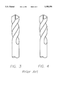
- FIG. 3 is a twist drill bit made according to the above-described present method for making twist drill bits of diameter greater than 5 mm having a cutting edge composed of PCD or PCBN.
- FIG. 4 is the blank into which a PCD or PCBN/tungsten carbide insert is brazed in the method of making the twist drill bits of FIG. 3.
- FIG. 5 is a standard twist drill bit according to the present invention.
- FIG. 6 is a cross-section through a drill blank from which the twist drill bit of FIG. 5 is machined in a manufacturing method according to the present invention.
- FIG. 7 is a slot drill bit according to the present invention.
- FIG. 8 is a cross-section through a blank from which the slot drill bit of FIG. 7 is machined in a manufacturing method according to the present invention.
- the standard twist drill bits of the invention comprise a body 1 of cemented tungsten carbide or similar material bonded to a layer 2 of PCD or PCBN.
- a suitable PCD is SYNDITE, a product of the De Beers Industrial Diamond Division (SYNDITE is a Registered Trade Mark of De Beers Industrial Diamond Division).
- the layer of PCD or PCBN is of substantially uniform axial thickness and extends across the top surface of the tip of the drill bit from the centre of the tip of the drill bit 3 to approximately the distal edge 4 of the tip of the drill bit.
- This configuration results in a cutting edge at the tip of the drill bit 5 (sometimes referred to in the art as a cutting lip) that is composed of PCD or PCBN, the thickness of the PCD or PCBN underlying the cutting edge being substantially uniform along the cutting edge.
- the thickness of the PCD or PCBN layer may be chosen so as to optimise the toughness and durability of the drill bit, and is typically 0.1 to 2 mm and preferably 0.5 to 1.5 mm.
- the substantially uniform thickness of the PCD or PCBN layer at the cutting edges enables repeated resharpening of the tool.
- the thickness of the PCD or PCBN layer can be chosen so as to optimise the toughness of the cutting edges.
- the limited thickness of PCD or PCBN layers that can be made by existing technology does not impose a limitation on the diameters of the drill bits of the invention. It will also be appreciated that it is straightforward to machine the drill bits of the invention to the optimised configuration for a twist drill bit, or to other desired configurations.
- the body of the drill bit may be in two or more parts joined together by brazing or other joining means.
- the tip of the drill bearing the PCD or PCBN layer 6 may be brazed to another piece of the body 7 that forms the shank of the drill bit.
- the twist drill bit of FIG. 5 is machined from the cylindrical blanks having a conical pointed tip of FIG. 6.
- the cross-sectional angle of the conical pointed tip (the tip angle) may be approximately 118°, the optimum cross-sectional angle for the tip of the finished drill.
- the cylindrical drill blank comprises a body 8 of cemented tungsten carbide or similar material having a layer of PCD or PCBN 9 in approximately a shape of a hollow cone of substantially uniform thickness extending from the centre of the tip of the drill to approximately the distal edge of the tip of the drill.
- the thickness of the PCD and PCBN layer is typically 0.1 to 2.0 mm, and preferably 0.5 to 1.5 mm.
- machining 5 is made from the drill blank by machining the body and PCD or PCBN layer of the drill blank as a whole into the desired shape for the twist drill bit. This machining may be carried out by grinding with diamond grinding wheels or by electric discharge machining or by other methods known in the art for the machining of very hard and wear-resistant materials.
- the blanks for the manufacture of the twist drills of the invention are made by subjecting a layer of diamond powder or cubic boron nitride powder combined with a suitable catalyst-solvent onto the appropriate area of the surface of a tungsten carbide body of the tool blank in a suitably shaped mould to high temperature and pressure.
- the PCD or PCBN layer is thus formed in situ, bonded to the appropriate area of the surface of the body of the tool blank.
- a method of manufacturing PCD layers bonded in situ onto shaped cemented tungsten carbide bodies in disclosed, for example, in European Patent Application No. 89308730.4 (De Beers Industrial Diamond Division (Proprietary) Limited) filed on 30th Aug. 1989.
- the requirements of the high temperature, high pressure apparatus mean that a PCD or PCBN layer is bonded in the bonding step to only a part of the body of the blank 10, corresponding to the tip of the finished drill.
- the part of the blank with the PCD or PCBN layer bonded to it is then attached to the remainder of the body of the blank 11 by brazing or other appropriate means.
- the slot drill of FIG. 7 comprises a body 12 of cemented tungsten carbide or similar material bonded to a layer of PCD or PCBN 13.
- the layer of PCD or PCBN extends across the top surface of the tip of slot drill and some distance down and around the sides of the slot drill below the tip, whereby the cutting edges of the slot drill are substantially composed of PCD or PCBN.
- the body of the slot drill bit may be in two parts joined together by brazing or other joining means.
- the tip of the slot drill bit bearing the PCD or PCBN layer (14) may be brazed to another piece of the body (15) that forms the shank of the slot drill bit.
- the slot drill bit of FIG. 7 is manufactured by machining it from the cylindrical blank of FIG. 8.
- the blank comprises a body of cemented tungsten carbide or similar material 16 and a layer of PCD or PCBN 17 of substantially uniform thickness and approximately in the form of a cup surrounding and bonded to the top part of the body.
- the thickness of the PCD or PCBN layer is typically between 0.1 and 2.0 mm, and preferably between 0.5 and 1.5 mm.
- the slot drill bits of the invention are made from the blanks by machining the body and the PCD or PCBN layer of the drill blank as a whole into the desired shape for the slot drill bit. This machining is carried out as described above.
- the blanks for the manufacture of the slot drill bits of the invention according to the process of the invention are made as described above by use of a suitably shaped tungsten carbide body and mould in a high temperature, high pressure synthesis step.
- the blanks may comprise two or more pieces brazed together as described above.
Abstract
Description
Claims (12)
Applications Claiming Priority (3)
| Application Number | Priority Date | Filing Date | Title |
|---|---|---|---|
| GB9117099 | 1991-08-08 | ||
| GB9117099A GB2259263B (en) | 1991-08-08 | 1991-08-08 | Wear resistant tools |
| PCT/GB1992/001478 WO1993002823A1 (en) | 1991-08-08 | 1992-08-10 | Wear resistant tools |
Publications (1)
| Publication Number | Publication Date |
|---|---|
| US5580196A true US5580196A (en) | 1996-12-03 |
Family
ID=10699676
Family Applications (1)
| Application Number | Title | Priority Date | Filing Date |
|---|---|---|---|
| US08/039,041 Expired - Lifetime US5580196A (en) | 1991-08-08 | 1992-08-10 | Wear resistant tools |
Country Status (8)
| Country | Link |
|---|---|
| US (1) | US5580196A (en) |
| EP (1) | EP0560951B1 (en) |
| JP (1) | JP3055803B2 (en) |
| AT (1) | ATE179105T1 (en) |
| DE (1) | DE69228984T2 (en) |
| ES (1) | ES2134217T3 (en) |
| GB (1) | GB2259263B (en) |
| WO (1) | WO1993002823A1 (en) |
Cited By (55)
| Publication number | Priority date | Publication date | Assignee | Title |
|---|---|---|---|---|
| US5762538A (en) * | 1996-03-25 | 1998-06-09 | Kennametal Inc. | Method and apparatus for honing an elongate rotary tool |
| US5919012A (en) * | 1995-09-28 | 1999-07-06 | The Institute Of Physical And Chemical Research (Riken) | Method of high speed cutting mold and ultra-high speed milling machine |
| WO2000020162A1 (en) * | 1998-10-02 | 2000-04-13 | Smith International, Inc. | Pcbn tips and coatings for use in cutting and machining hard materials |
| US6056485A (en) * | 1998-09-01 | 2000-05-02 | Kennametal Inc. | Ramp plunge and feed milling cutter |
| US6132148A (en) * | 1996-02-15 | 2000-10-17 | Habit Diamond Limited | Machining tool and method for forming same |
| US6152660A (en) * | 1997-12-22 | 2000-11-28 | Papajewski; Joerg | Drilling tool for bores in solid material |
| US6478887B1 (en) | 1998-12-16 | 2002-11-12 | Smith International, Inc. | Boronized wear-resistant materials and methods thereof |
| US20030198525A1 (en) * | 2002-04-18 | 2003-10-23 | Nachi-Fujikoshi Corp. | Cemented carbide ball end mill |
| US6663326B1 (en) * | 1999-05-24 | 2003-12-16 | Honda Giken Kogyo Kabushiki Kaisha | Cutting tip and manufacturing method thereof |
| US20040185948A1 (en) * | 2001-07-25 | 2004-09-23 | Wolfgang Muller | Thread former or tap |
| KR20050009446A (en) * | 2003-07-16 | 2005-01-25 | 한국항공우주산업 주식회사 | Countersink Forming Cutter |
| US20050163579A1 (en) * | 2003-06-27 | 2005-07-28 | Jorg Guhring | Deburring tool |
| US7147939B2 (en) | 2003-02-27 | 2006-12-12 | Kennametal Inc. | Coated carbide tap |
| US20070029116A1 (en) * | 2005-08-03 | 2007-02-08 | Keshavan Madapusi K | High energy cutting elements and bits incorporating the same |
| US7228922B1 (en) | 2004-06-08 | 2007-06-12 | Devall Donald L | Drill bit |
| US20070292269A1 (en) * | 2006-03-30 | 2007-12-20 | Aisin Aw Co., Ltd. | Automatic transmission and production method of impeller hub for automatic transmission |
| US7513319B2 (en) | 2004-06-08 | 2009-04-07 | Devall Donald L | Reamer bit |
| US20090116913A1 (en) * | 2007-11-01 | 2009-05-07 | Gm Global Technology Operations Inc. | Polycrystalline Diamond Cutting Tool with Coated Body |
| DE112008000901T5 (en) | 2007-04-03 | 2010-02-18 | Cho, H. Sam, Salt Lake City | Contoured PCD and PKB for spiral drill bits and milling and process for their shaping |
| US20100098505A1 (en) * | 2008-10-17 | 2010-04-22 | Garrick Richard M | Shielded pcd or pcbn cutting tools |
| US20110176879A1 (en) * | 2010-01-20 | 2011-07-21 | Cornelis Roelof Jonker | Superhard body, tool and method for making same |
| ITBO20100069A1 (en) * | 2010-02-09 | 2011-08-10 | Cruing Italy S R L | DRILLING TIP |
| US20110268518A1 (en) * | 2010-04-30 | 2011-11-03 | Karthik Sampath | Rotary cutting tool having pcd cutting tip |
| GB2481295A (en) * | 2010-06-16 | 2011-12-21 | Element Six Ltd | A cutter element for a rotary machine |
| WO2011089555A3 (en) * | 2010-01-20 | 2012-01-05 | Element Six (Production) Pty Ltd | Superhard body, tool and method for making same |
| WO2012035070A1 (en) | 2010-09-17 | 2012-03-22 | Element Six Limited | Twist drill assembly, components for same and method for making same |
| CN102451930A (en) * | 2010-10-19 | 2012-05-16 | 钴碳化钨硬质合金公司 | Rotary cutting tool having pcd cutting tip |
| WO2012069465A1 (en) | 2010-11-25 | 2012-05-31 | Element Six Limited | Bit for a rotary drill |
| US20120288337A1 (en) * | 2011-05-11 | 2012-11-15 | Karthik Sampath | Rotary cutting tool having pcd cutting tip |
| WO2012171915A1 (en) | 2011-06-13 | 2012-12-20 | Element Six Abrasives S.A. | Twist drill tips, precursor constructions for use in making same, and methods for making and using same |
| US20130047397A1 (en) * | 2010-02-12 | 2013-02-28 | Cornelis Roelof Jonker | Superhard tool tip, method for making same and tool comprising same |
| US9028575B2 (en) | 2010-09-08 | 2015-05-12 | Element Six Limited | EDM cuttable, high CBN content solid PCBN compact |
| US9085074B2 (en) | 2011-03-22 | 2015-07-21 | Black & Decker Inc. | Chisels |
| USD734792S1 (en) * | 2013-03-15 | 2015-07-21 | Black & Decker Inc. | Drill bit |
| USD737875S1 (en) * | 2013-03-15 | 2015-09-01 | Black & Decker Inc. | Drill bit |
| US20150266120A1 (en) * | 2012-10-15 | 2015-09-24 | Kennametal Inc. | Reamer |
| DE102014207502A1 (en) * | 2014-04-17 | 2015-10-22 | Kennametal Inc. | Rotary tool and tool head |
| EP1931490B1 (en) | 2005-10-04 | 2015-12-09 | Gühring KG | Chip removing tool |
| US9333564B2 (en) | 2013-03-15 | 2016-05-10 | Black & Decker Inc. | Drill bit |
| US9468980B2 (en) | 2007-04-03 | 2016-10-18 | H. Sam Cho | Contoured PCD and PCBN segments for cutting tools containing such segments |
| US20170036311A1 (en) * | 2013-03-15 | 2017-02-09 | Sandvik Intellectual Property Ab | Method of joining sintered parts of different sizes and shapes |
| US20170072477A1 (en) * | 2014-03-21 | 2017-03-16 | Gühring KG | Partially hardened rotary tool and corresponding production method |
| CN106827038A (en) * | 2016-12-30 | 2017-06-13 | 无锡国宏硬质合金模具刃具有限公司 | A kind of circuit boring PCD drill bits and processing technology |
| US9881299B2 (en) | 2008-03-13 | 2018-01-30 | Giftya Llc | System and method for processing financial transactions |
| CN107952986A (en) * | 2016-10-17 | 2018-04-24 | 上海精韧激光科技有限公司 | For manufacturing the blank and its manufacture method of cutting element |
| CN108430681A (en) * | 2016-11-15 | 2018-08-21 | 住友电工硬质合金株式会社 | Cutting element |
| US10121127B1 (en) | 2008-03-13 | 2018-11-06 | Giftya Llc | System and method for processing group gift cards |
| CN109996632A (en) * | 2016-11-15 | 2019-07-09 | 住友电工硬质合金株式会社 | Cutting element |
| US10489776B2 (en) | 2008-03-13 | 2019-11-26 | Giftya Llc | System and method for managing gift credits |
| JPWO2019039001A1 (en) * | 2017-08-22 | 2020-07-30 | 住友電工ハードメタル株式会社 | Rotary cutting tool and manufacturing method thereof |
| US10846725B2 (en) | 2008-03-13 | 2020-11-24 | Giftya Llc | Method for rule-based gift giving |
| US10949833B2 (en) | 2008-03-13 | 2021-03-16 | Giftya Llc | Technologies for generating and displaying virtual and interactive egifts |
| US11015397B2 (en) | 2014-12-31 | 2021-05-25 | Schlumberger Technology Corporation | Cutting elements and drill bits incorporating the same |
| WO2021197215A1 (en) * | 2020-03-30 | 2021-10-07 | 上海名古屋精密工具股份有限公司 | Blank body, and cutting tool having front cutter face made of helical superhard material |
| CN114178589A (en) * | 2021-10-20 | 2022-03-15 | 镇江尧研工具有限公司 | Four-blade four-spiral high-hardness drill bit |
Families Citing this family (15)
| Publication number | Priority date | Publication date | Assignee | Title |
|---|---|---|---|---|
| KR100394287B1 (en) * | 1994-11-10 | 2003-11-28 | 켄나메탈 헤르텔 아게 베르크조위게 플러스 하르트쉬토페 | Boring tool |
| US5809848A (en) * | 1996-02-12 | 1998-09-22 | Credo Tool Company | Method of making a carbide cutting insert |
| DE19905735A1 (en) * | 1999-02-11 | 2000-08-17 | Kennametal Inc | Process for producing a cutting tool and cutting tool |
| JP4683167B2 (en) * | 2000-04-18 | 2011-05-11 | ジーエヌツール株式会社 | Drill |
| EP1351798B1 (en) * | 2000-12-21 | 2007-03-14 | Element Six (PTY) Ltd | Method of making a cutting tool |
| GB0320148D0 (en) * | 2003-08-28 | 2003-10-01 | Dormer Tools Sheffield Ltd | Partially coated drill tool |
| DE102005041331A1 (en) * | 2005-08-29 | 2007-03-01 | MAPAL Fabrik für Präzisionswerkzeuge Dr. Kress KG | A method for manufacturing small diameter hardened piercing tools has a cylindrical shaft and head with a hard cap soldered together prior to machining |
| DE102008052743A1 (en) | 2008-10-22 | 2010-04-29 | MAPAL Fabrik für Präzisionswerkzeuge Dr. Kress KG | Tool i.e. twist drill, for machining workpiece, has regions provided along axial extension of tool, geometrically defined cutting edge and center axis, where regions are alternately made of ductile and hard materials |
| JP5617428B2 (en) * | 2009-08-20 | 2014-11-05 | 日立ツール株式会社 | Small diameter drill for machining hardened steel |
| GB201116115D0 (en) | 2011-09-19 | 2011-11-02 | White Jamie | Combination drill reamer for machining advanced materials |
| US9194189B2 (en) | 2011-09-19 | 2015-11-24 | Baker Hughes Incorporated | Methods of forming a cutting element for an earth-boring tool, a related cutting element, and an earth-boring tool including such a cutting element |
| DE102015013687A1 (en) * | 2015-10-21 | 2017-04-27 | Audi Ag | Method for producing at least one welding pin |
| JP6655193B2 (en) * | 2016-09-20 | 2020-02-26 | 本田技研工業株式会社 | Manufacturing method of PCD drill |
| EP3950194A4 (en) | 2019-03-26 | 2023-03-15 | Mitsubishi Materials Corporation | Base material for hard sintered compact, hard sintered compact, and cutting tool |
| JP7313599B2 (en) | 2019-03-27 | 2023-07-25 | 三菱マテリアル株式会社 | Base material for hard sintered body, hard sintered body and cutting tool |
Citations (17)
| Publication number | Priority date | Publication date | Assignee | Title |
|---|---|---|---|---|
| US3912414A (en) * | 1972-06-09 | 1975-10-14 | Sumitomo Electric Industries | Cemented carbide twist drill |
| FR2270986A1 (en) * | 1974-05-16 | 1975-12-12 | Chemetal Corp | |
| US4160616A (en) * | 1977-10-03 | 1979-07-10 | Winblad Michael E | Drill containing minimum cutting material |
| JPS5566A (en) * | 1978-06-16 | 1980-01-05 | Mitsubishi Monsanto Chem Co | Tea processor |
| EP0223585A2 (en) * | 1985-11-19 | 1987-05-27 | Sumitomo Electric Industries Limited | A hard sintered compact for a tool |
| US4679971A (en) * | 1982-09-02 | 1987-07-14 | Hartmetallwerkzeugfabrik Andreas Maier Gmbh & Co. Kg | Rotary cutting tool and process for making same |
| DE3620115A1 (en) * | 1986-06-14 | 1987-12-17 | Hawera Praezisionswerkzeuge | Contour milling device |
| US4764434A (en) * | 1987-06-26 | 1988-08-16 | Sandvik Aktiebolag | Diamond tools for rock drilling and machining |
| JPS6478710A (en) * | 1987-09-21 | 1989-03-24 | Kokutou Dengiyoushiya Kk | Diamond galvanized drill, manufacture thereof and boring method |
| US4880707A (en) * | 1984-06-12 | 1989-11-14 | Sumitomo Electric Industries Ltd. | Stick of composite materials and process for preparation thereof |
| EP0357379A2 (en) * | 1988-08-31 | 1990-03-07 | De Beers Industrial Diamond Division (Proprietary) Limited | Manufacture of abrasive products |
| JPH0373210A (en) * | 1989-05-25 | 1991-03-28 | G N Tool Kk | High hardness cutting tool and manufacture and use thereof |
| US5020394A (en) * | 1988-10-14 | 1991-06-04 | Sumitomo Electric Industries, Ltd. | Polycrystal diamond fluted tool and a process for the production of the same |
| US5031484A (en) * | 1990-05-24 | 1991-07-16 | Smith International, Inc. | Diamond fluted end mill |
| JPH03170216A (en) * | 1989-11-28 | 1991-07-23 | Mitsubishi Materials Corp | Miniature drill of rigid surface layer coated cemented carbide |
| JPH03170215A (en) * | 1989-11-28 | 1991-07-23 | Mitsubishi Materials Corp | Miniature drill of rigid surface layer coated cemented carbide and manufacture thereof |
| US5226760A (en) * | 1990-02-07 | 1993-07-13 | Gn Tool Co., Ltd. | Cutting tool with twisted edge and manufacturing method thereof |
Family Cites Families (1)
| Publication number | Priority date | Publication date | Assignee | Title |
|---|---|---|---|---|
| US4713286A (en) | 1985-10-31 | 1987-12-15 | Precorp, Inc. | Printed circuit board drill and method of manufacture |
-
1991
- 1991-08-08 GB GB9117099A patent/GB2259263B/en not_active Expired - Lifetime
-
1992
- 1992-08-10 EP EP92917576A patent/EP0560951B1/en not_active Expired - Lifetime
- 1992-08-10 ES ES92917576T patent/ES2134217T3/en not_active Expired - Lifetime
- 1992-08-10 DE DE69228984T patent/DE69228984T2/en not_active Expired - Lifetime
- 1992-08-10 US US08/039,041 patent/US5580196A/en not_active Expired - Lifetime
- 1992-08-10 JP JP5503443A patent/JP3055803B2/en not_active Expired - Lifetime
- 1992-08-10 WO PCT/GB1992/001478 patent/WO1993002823A1/en active IP Right Grant
- 1992-08-10 AT AT92917576T patent/ATE179105T1/en not_active IP Right Cessation
Patent Citations (18)
| Publication number | Priority date | Publication date | Assignee | Title |
|---|---|---|---|---|
| US3912414A (en) * | 1972-06-09 | 1975-10-14 | Sumitomo Electric Industries | Cemented carbide twist drill |
| FR2270986A1 (en) * | 1974-05-16 | 1975-12-12 | Chemetal Corp | |
| GB1509076A (en) * | 1974-05-16 | 1978-04-26 | Chemetal Corp | Cutting tool and method for making same |
| US4160616A (en) * | 1977-10-03 | 1979-07-10 | Winblad Michael E | Drill containing minimum cutting material |
| JPS5566A (en) * | 1978-06-16 | 1980-01-05 | Mitsubishi Monsanto Chem Co | Tea processor |
| US4679971A (en) * | 1982-09-02 | 1987-07-14 | Hartmetallwerkzeugfabrik Andreas Maier Gmbh & Co. Kg | Rotary cutting tool and process for making same |
| US4880707A (en) * | 1984-06-12 | 1989-11-14 | Sumitomo Electric Industries Ltd. | Stick of composite materials and process for preparation thereof |
| EP0223585A2 (en) * | 1985-11-19 | 1987-05-27 | Sumitomo Electric Industries Limited | A hard sintered compact for a tool |
| DE3620115A1 (en) * | 1986-06-14 | 1987-12-17 | Hawera Praezisionswerkzeuge | Contour milling device |
| US4764434A (en) * | 1987-06-26 | 1988-08-16 | Sandvik Aktiebolag | Diamond tools for rock drilling and machining |
| JPS6478710A (en) * | 1987-09-21 | 1989-03-24 | Kokutou Dengiyoushiya Kk | Diamond galvanized drill, manufacture thereof and boring method |
| EP0357379A2 (en) * | 1988-08-31 | 1990-03-07 | De Beers Industrial Diamond Division (Proprietary) Limited | Manufacture of abrasive products |
| US5020394A (en) * | 1988-10-14 | 1991-06-04 | Sumitomo Electric Industries, Ltd. | Polycrystal diamond fluted tool and a process for the production of the same |
| JPH0373210A (en) * | 1989-05-25 | 1991-03-28 | G N Tool Kk | High hardness cutting tool and manufacture and use thereof |
| JPH03170216A (en) * | 1989-11-28 | 1991-07-23 | Mitsubishi Materials Corp | Miniature drill of rigid surface layer coated cemented carbide |
| JPH03170215A (en) * | 1989-11-28 | 1991-07-23 | Mitsubishi Materials Corp | Miniature drill of rigid surface layer coated cemented carbide and manufacture thereof |
| US5226760A (en) * | 1990-02-07 | 1993-07-13 | Gn Tool Co., Ltd. | Cutting tool with twisted edge and manufacturing method thereof |
| US5031484A (en) * | 1990-05-24 | 1991-07-16 | Smith International, Inc. | Diamond fluted end mill |
Cited By (100)
| Publication number | Priority date | Publication date | Assignee | Title |
|---|---|---|---|---|
| US5919012A (en) * | 1995-09-28 | 1999-07-06 | The Institute Of Physical And Chemical Research (Riken) | Method of high speed cutting mold and ultra-high speed milling machine |
| US6132148A (en) * | 1996-02-15 | 2000-10-17 | Habit Diamond Limited | Machining tool and method for forming same |
| US5762538A (en) * | 1996-03-25 | 1998-06-09 | Kennametal Inc. | Method and apparatus for honing an elongate rotary tool |
| US6152660A (en) * | 1997-12-22 | 2000-11-28 | Papajewski; Joerg | Drilling tool for bores in solid material |
| US6056485A (en) * | 1998-09-01 | 2000-05-02 | Kennametal Inc. | Ramp plunge and feed milling cutter |
| US6698415B2 (en) | 1998-10-02 | 2004-03-02 | Smith International, Inc. | Method for cutting and machining hard materials |
| WO2000020162A1 (en) * | 1998-10-02 | 2000-04-13 | Smith International, Inc. | Pcbn tips and coatings for use in cutting and machining hard materials |
| US6478887B1 (en) | 1998-12-16 | 2002-11-12 | Smith International, Inc. | Boronized wear-resistant materials and methods thereof |
| US6663326B1 (en) * | 1999-05-24 | 2003-12-16 | Honda Giken Kogyo Kabushiki Kaisha | Cutting tip and manufacturing method thereof |
| US6694847B2 (en) | 1999-05-24 | 2004-02-24 | Honda Giken Kogyo Kabushiki Kaisha | Cutting tip and method thereof |
| US20040185948A1 (en) * | 2001-07-25 | 2004-09-23 | Wolfgang Muller | Thread former or tap |
| US7112143B2 (en) * | 2001-07-25 | 2006-09-26 | Fette Gmbh | Thread former or tap |
| US20030198525A1 (en) * | 2002-04-18 | 2003-10-23 | Nachi-Fujikoshi Corp. | Cemented carbide ball end mill |
| US6953310B2 (en) * | 2002-04-18 | 2005-10-11 | Nachi-Fujikoshi Corp. | Cemented carbide ball end mill |
| US7147939B2 (en) | 2003-02-27 | 2006-12-12 | Kennametal Inc. | Coated carbide tap |
| US20050163579A1 (en) * | 2003-06-27 | 2005-07-28 | Jorg Guhring | Deburring tool |
| US7513721B2 (en) * | 2003-06-27 | 2009-04-07 | Jörg Gühring | Deburring tool |
| KR20050009446A (en) * | 2003-07-16 | 2005-01-25 | 한국항공우주산업 주식회사 | Countersink Forming Cutter |
| US7228922B1 (en) | 2004-06-08 | 2007-06-12 | Devall Donald L | Drill bit |
| US7513319B2 (en) | 2004-06-08 | 2009-04-07 | Devall Donald L | Reamer bit |
| US20070029116A1 (en) * | 2005-08-03 | 2007-02-08 | Keshavan Madapusi K | High energy cutting elements and bits incorporating the same |
| US7451838B2 (en) | 2005-08-03 | 2008-11-18 | Smith International, Inc. | High energy cutting elements and bits incorporating the same |
| US20090057033A1 (en) * | 2005-08-03 | 2009-03-05 | Keshavan Madapusi K | High energy cutting elements and bits incorporating the same |
| EP1931490B1 (en) | 2005-10-04 | 2015-12-09 | Gühring KG | Chip removing tool |
| US20070292269A1 (en) * | 2006-03-30 | 2007-12-20 | Aisin Aw Co., Ltd. | Automatic transmission and production method of impeller hub for automatic transmission |
| US7637100B2 (en) * | 2006-03-30 | 2009-12-29 | Aisin Aw Co., Ltd | Automatic transmission and production method of impeller hub for automatic transmission |
| DE112007000034B4 (en) * | 2006-03-30 | 2012-11-08 | Aisin Aw Co., Ltd. | Automatic transmission and method of manufacture of paddle wheel hub used therein |
| DE112008000901T5 (en) | 2007-04-03 | 2010-02-18 | Cho, H. Sam, Salt Lake City | Contoured PCD and PKB for spiral drill bits and milling and process for their shaping |
| US9468980B2 (en) | 2007-04-03 | 2016-10-18 | H. Sam Cho | Contoured PCD and PCBN segments for cutting tools containing such segments |
| US8052765B2 (en) | 2007-04-03 | 2011-11-08 | Cho H Sam | Contoured PCD and PCBN for twist drill tips and end mills and methods of forming the same |
| US20090116913A1 (en) * | 2007-11-01 | 2009-05-07 | Gm Global Technology Operations Inc. | Polycrystalline Diamond Cutting Tool with Coated Body |
| US9079260B2 (en) * | 2007-11-01 | 2015-07-14 | GM Global Technology Operations LLC | Polycrystalline diamond cutting tool with coated body |
| US11379822B2 (en) | 2008-03-13 | 2022-07-05 | Giftya, Llc | System and method for splitting a transaction |
| US11449859B2 (en) | 2008-03-13 | 2022-09-20 | Giftya Llc | System and method for enabling a user to choose how to redeem a gift credit |
| US10846725B2 (en) | 2008-03-13 | 2020-11-24 | Giftya Llc | Method for rule-based gift giving |
| US11403618B2 (en) | 2008-03-13 | 2022-08-02 | Giftya Llc | System and method for managing gifts |
| US10121127B1 (en) | 2008-03-13 | 2018-11-06 | Giftya Llc | System and method for processing group gift cards |
| US10489776B2 (en) | 2008-03-13 | 2019-11-26 | Giftya Llc | System and method for managing gift credits |
| US10949833B2 (en) | 2008-03-13 | 2021-03-16 | Giftya Llc | Technologies for generating and displaying virtual and interactive egifts |
| US11049157B2 (en) | 2008-03-13 | 2021-06-29 | Giftya Llc | System and method for managing gift credits for corporate benefits and offers |
| US11392930B2 (en) | 2008-03-13 | 2022-07-19 | Giftya Llc | System and method for processing gift transfers via a social network |
| US11392929B2 (en) | 2008-03-13 | 2022-07-19 | Giftya Llc | System and method for processing gifts between different exchange medium |
| US11416846B2 (en) | 2008-03-13 | 2022-08-16 | Giftya Llc | System and method for managing gifts |
| US11379823B2 (en) | 2008-03-13 | 2022-07-05 | Giftya Llc | System and method for processing group gift cards using a temporary, limited scope social networking entity |
| US9881299B2 (en) | 2008-03-13 | 2018-01-30 | Giftya Llc | System and method for processing financial transactions |
| US11429953B2 (en) | 2008-03-13 | 2022-08-30 | Giftya Llc | System and method for processing a gift involving separate transactions |
| US11455619B2 (en) | 2008-03-13 | 2022-09-27 | Giftya Llc | Technologies for generating and displaying virtual and interactive egifts |
| US11676131B2 (en) | 2008-03-13 | 2023-06-13 | Giftya Llc | System and method for managing gifts |
| US11392928B2 (en) | 2008-03-13 | 2022-07-19 | Giftya Llc | System and method for processing gift cards by intercepting a purchasing transaction |
| US8342780B2 (en) * | 2008-10-17 | 2013-01-01 | Precorp, Inc. | Shielded PCD or PCBN cutting tools |
| US20100098505A1 (en) * | 2008-10-17 | 2010-04-22 | Garrick Richard M | Shielded pcd or pcbn cutting tools |
| WO2011089555A3 (en) * | 2010-01-20 | 2012-01-05 | Element Six (Production) Pty Ltd | Superhard body, tool and method for making same |
| CN102947027A (en) * | 2010-01-20 | 2013-02-27 | 六号元素磨料股份有限公司 | Superhard body, tool and method for making same |
| US20110176879A1 (en) * | 2010-01-20 | 2011-07-21 | Cornelis Roelof Jonker | Superhard body, tool and method for making same |
| ITBO20100069A1 (en) * | 2010-02-09 | 2011-08-10 | Cruing Italy S R L | DRILLING TIP |
| US9844814B2 (en) * | 2010-02-12 | 2017-12-19 | Element Six Abrasives S.A. | Superhard tool tip, method for making same and tool comprising same |
| US20130047397A1 (en) * | 2010-02-12 | 2013-02-28 | Cornelis Roelof Jonker | Superhard tool tip, method for making same and tool comprising same |
| US20110268518A1 (en) * | 2010-04-30 | 2011-11-03 | Karthik Sampath | Rotary cutting tool having pcd cutting tip |
| US9539652B2 (en) * | 2010-04-30 | 2017-01-10 | Kennametal Inc. | Rotary cutting tool having PCD cutting tip |
| US10328536B2 (en) | 2010-04-30 | 2019-06-25 | Kennametal Inc. | Rotary cutting tool having PCD cutting tip |
| US9393629B2 (en) | 2010-06-16 | 2016-07-19 | Element Six Abrasives S.A. | Cutter elements, rotary machine tools comprising same and method for making same |
| GB2481295B (en) * | 2010-06-16 | 2014-12-17 | Element Six Ltd | Cutter elements, rotary machine tools comprising same and method for using same |
| GB2481295A (en) * | 2010-06-16 | 2011-12-21 | Element Six Ltd | A cutter element for a rotary machine |
| US9028575B2 (en) | 2010-09-08 | 2015-05-12 | Element Six Limited | EDM cuttable, high CBN content solid PCBN compact |
| US9302332B2 (en) | 2010-09-17 | 2016-04-05 | Element Six Limited | Twist drill assembly, components for same and method for making same |
| WO2012035070A1 (en) | 2010-09-17 | 2012-03-22 | Element Six Limited | Twist drill assembly, components for same and method for making same |
| CN102451930A (en) * | 2010-10-19 | 2012-05-16 | 钴碳化钨硬质合金公司 | Rotary cutting tool having pcd cutting tip |
| WO2012069465A1 (en) | 2010-11-25 | 2012-05-31 | Element Six Limited | Bit for a rotary drill |
| US9724763B2 (en) * | 2010-11-25 | 2017-08-08 | Element Six Limited | Bit for a rotary drill |
| US20140037393A1 (en) * | 2010-11-25 | 2014-02-06 | Element Six Limited | Bit for a rotary drill |
| US9085074B2 (en) | 2011-03-22 | 2015-07-21 | Black & Decker Inc. | Chisels |
| US9333635B2 (en) | 2011-03-22 | 2016-05-10 | Black & Decker Inc. | Chisels |
| US8882412B2 (en) * | 2011-05-11 | 2014-11-11 | Kennametal Inc. | Rotary cutting tool having PCD cutting tip |
| US20120288337A1 (en) * | 2011-05-11 | 2012-11-15 | Karthik Sampath | Rotary cutting tool having pcd cutting tip |
| US9975185B2 (en) | 2011-06-13 | 2018-05-22 | Element Sux Abrasives S.A. | Twist drill tips, precursor constructions for use in making same, and methods for making and using same |
| WO2012171915A1 (en) | 2011-06-13 | 2012-12-20 | Element Six Abrasives S.A. | Twist drill tips, precursor constructions for use in making same, and methods for making and using same |
| US10493545B2 (en) | 2012-10-15 | 2019-12-03 | Kennametal Inc. | Reamer |
| US9802260B2 (en) * | 2012-10-15 | 2017-10-31 | Kennametal Inc | Reamer |
| US20150266120A1 (en) * | 2012-10-15 | 2015-09-24 | Kennametal Inc. | Reamer |
| USD734792S1 (en) * | 2013-03-15 | 2015-07-21 | Black & Decker Inc. | Drill bit |
| USD737875S1 (en) * | 2013-03-15 | 2015-09-01 | Black & Decker Inc. | Drill bit |
| US9333564B2 (en) | 2013-03-15 | 2016-05-10 | Black & Decker Inc. | Drill bit |
| US20170036311A1 (en) * | 2013-03-15 | 2017-02-09 | Sandvik Intellectual Property Ab | Method of joining sintered parts of different sizes and shapes |
| US20170072477A1 (en) * | 2014-03-21 | 2017-03-16 | Gühring KG | Partially hardened rotary tool and corresponding production method |
| US9901994B2 (en) | 2014-04-17 | 2018-02-27 | Kennametal Inc. | Rotating tool and tool head |
| CN104999125A (en) * | 2014-04-17 | 2015-10-28 | 钴碳化钨硬质合金公司 | Rotating tool and tool head |
| DE102014207502B4 (en) | 2014-04-17 | 2022-11-24 | Kennametal Inc. | rotary tool and tool head |
| CN104999125B (en) * | 2014-04-17 | 2020-09-04 | 钴碳化钨硬质合金公司 | Rotary tool and tool head |
| DE102014207502A1 (en) * | 2014-04-17 | 2015-10-22 | Kennametal Inc. | Rotary tool and tool head |
| US11015397B2 (en) | 2014-12-31 | 2021-05-25 | Schlumberger Technology Corporation | Cutting elements and drill bits incorporating the same |
| CN107952986A (en) * | 2016-10-17 | 2018-04-24 | 上海精韧激光科技有限公司 | For manufacturing the blank and its manufacture method of cutting element |
| CN108430681A (en) * | 2016-11-15 | 2018-08-21 | 住友电工硬质合金株式会社 | Cutting element |
| CN109996632A (en) * | 2016-11-15 | 2019-07-09 | 住友电工硬质合金株式会社 | Cutting element |
| EP3542934A4 (en) * | 2016-11-15 | 2020-06-10 | Sumitomo Electric Hardmetal Corp. | Cutting tool |
| CN106827038A (en) * | 2016-12-30 | 2017-06-13 | 无锡国宏硬质合金模具刃具有限公司 | A kind of circuit boring PCD drill bits and processing technology |
| JP7036437B2 (en) | 2017-08-22 | 2022-03-15 | 住友電工ハードメタル株式会社 | Rotary cutting tools and their manufacturing methods |
| JPWO2019039001A1 (en) * | 2017-08-22 | 2020-07-30 | 住友電工ハードメタル株式会社 | Rotary cutting tool and manufacturing method thereof |
| WO2021197215A1 (en) * | 2020-03-30 | 2021-10-07 | 上海名古屋精密工具股份有限公司 | Blank body, and cutting tool having front cutter face made of helical superhard material |
| CN114178589A (en) * | 2021-10-20 | 2022-03-15 | 镇江尧研工具有限公司 | Four-blade four-spiral high-hardness drill bit |
| CN114178589B (en) * | 2021-10-20 | 2023-12-01 | 镇江尧研工具有限公司 | Four-edge four-screw high-hardness drill bit |
Also Published As
| Publication number | Publication date |
|---|---|
| ES2134217T3 (en) | 1999-10-01 |
| GB2259263B (en) | 1995-11-22 |
| GB2259263A (en) | 1993-03-10 |
| GB9117099D0 (en) | 1991-09-25 |
| JPH06508566A (en) | 1994-09-29 |
| EP0560951B1 (en) | 1999-04-21 |
| ATE179105T1 (en) | 1999-05-15 |
| DE69228984D1 (en) | 1999-05-27 |
| DE69228984T2 (en) | 1999-12-09 |
| EP0560951A1 (en) | 1993-09-22 |
| JP3055803B2 (en) | 2000-06-26 |
| WO1993002823A1 (en) | 1993-02-18 |
Similar Documents
| Publication | Publication Date | Title |
|---|---|---|
| US5580196A (en) | Wear resistant tools | |
| US6511265B1 (en) | Composite rotary tool and tool fabrication method | |
| US5115697A (en) | Diamond rotary cutter flute geometry | |
| EP0157625B1 (en) | Composite tool | |
| US9468980B2 (en) | Contoured PCD and PCBN segments for cutting tools containing such segments | |
| US8052765B2 (en) | Contoured PCD and PCBN for twist drill tips and end mills and methods of forming the same | |
| US6152657A (en) | Center cutting end mill | |
| US6447560B2 (en) | Method for forming a superabrasive polycrystalline cutting tool with an integral chipbreaker feature | |
| EP2533922B1 (en) | Superhard tool tip and use thereof | |
| US20030175085A1 (en) | Rotary cutting tool | |
| IE65906B1 (en) | Rotary cutter with diamond-like cutting edges | |
| US20030154840A1 (en) | Disposable food delivery apparatus | |
| JPH0373210A (en) | High hardness cutting tool and manufacture and use thereof | |
| US20220339720A1 (en) | Green body and cutting tool having helical superhard-material rake face | |
| Hirst | Imperialism and Finance | |
| US20020170407A1 (en) | Polycrystalline cubic baron nitride (PCBN) woodworking tools and methods | |
| KR20030051700A (en) | Abrasive and wear resistant material | |
| Heath | Ultrahard tool materials | |
| JP2000190108A (en) | Polycrystalline hard sintered body cutting tool | |
| JP4721644B2 (en) | Milling tool and inspection method thereof | |
| WO2003083148A1 (en) | Polycrystalline material element with improved wear resistance and methods of manufacture thereof | |
| US20050076755A1 (en) | Method and apparatus for machining fiber cement | |
| KR20220149010A (en) | Manufacturing of the super hard materials with bottom cutting edge | |
| CN110539007A (en) | Blank having a hard material and use thereof for producing a tool |
Legal Events
| Date | Code | Title | Description |
|---|---|---|---|
| AS | Assignment |
Owner name: HABIT DIAMOND LIMITED, ENGLAND Free format text: ASSIGNMENT OF ASSIGNORS INTEREST;ASSIGNOR:THOMPSON, MICHAEL FREDERICK;REEL/FRAME:006710/0330 Effective date: 19930419 |
|
| STPP | Information on status: patent application and granting procedure in general |
Free format text: APPLICATION UNDERGOING PREEXAM PROCESSING |
|
| AS | Assignment |
Owner name: CASHGIFT LIMITED, UNITED KINGDOM Free format text: ASSIGNMENT OF ASSIGNORS INTEREST;ASSIGNORS:HABIT DIAMOND LIMITED;GRIFFITHS, ALAN (ADMINISTRATIVE RECEIVER);SHIERSON, MICHAEL BRIAN (ADMINISTRATIVE RECEIVER);REEL/FRAME:007627/0622 Effective date: 19931223 |
|
| AS | Assignment |
Owner name: HABIT DIAMOND LIMITED, UNITED KINGDOM Free format text: CHANGE OF NAME;ASSIGNOR:CASHGIFT LIMITED;REEL/FRAME:007602/0322 Effective date: 19940203 |
|
| FPAY | Fee payment |
Year of fee payment: 4 |
|
| AS | Assignment |
Owner name: ABRASIVE TECHNOLOGY LIMITED, ENGLAND Free format text: CHANGE OF NAME;ASSIGNOR:HABIT DIAMOND LIMITED;REEL/FRAME:012841/0918 Effective date: 20011220 |
|
| FPAY | Fee payment |
Year of fee payment: 8 |
|
| FPAY | Fee payment |
Year of fee payment: 12 |