US554274A - Tile roof - Google Patents
Tile roof Download PDFInfo
- Publication number
- US554274A US554274A US554274DA US554274A US 554274 A US554274 A US 554274A US 554274D A US554274D A US 554274DA US 554274 A US554274 A US 554274A
- Authority
- US
- United States
- Prior art keywords
- tile
- roof
- tiles
- gutter
- sections
- Prior art date
- Legal status (The legal status is an assumption and is not a legal conclusion. Google has not performed a legal analysis and makes no representation as to the accuracy of the status listed.)
- Expired - Lifetime
Links
- 238000010276 construction Methods 0.000 description 14
- 239000011324 bead Substances 0.000 description 4
- 230000015572 biosynthetic process Effects 0.000 description 2
- 239000004568 cement Substances 0.000 description 2
- 240000001973 Ficus microcarpa Species 0.000 description 1
- 230000006978 adaptation Effects 0.000 description 1
- 239000011449 brick Substances 0.000 description 1
- 238000006073 displacement reaction Methods 0.000 description 1
- XLYOFNOQVPJJNP-UHFFFAOYSA-N water Substances O XLYOFNOQVPJJNP-UHFFFAOYSA-N 0.000 description 1
Images



Classifications
-
- E—FIXED CONSTRUCTIONS
- E04—BUILDING
- E04D—ROOF COVERINGS; SKY-LIGHTS; GUTTERS; ROOF-WORKING TOOLS
- E04D13/00—Special arrangements or devices in connection with roof coverings; Protection against birds; Roof drainage ; Sky-lights
- E04D13/04—Roof drainage; Drainage fittings in flat roofs, balconies or the like
- E04D13/064—Gutters
Definitions
- My invention relates to tile-roof construction; and the objects of my invention are to provide an improved construction of tile shingles, gutters, valleys, ridge-covers, and other parts forming the roof-cover, to provide improved means for connecting said parts with each other and with the roof-frame,and to produce other improvements in details of construction and arrangement, which will be more fully pointed out hereinafter.
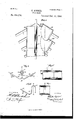
- Figure l is a view in elevation of a roof side having my improvements thereon.
- Fig. 2 is a sectional View on line 00 cc of Fig. 1.
- Fig. 3 is a detail view in elevation showing sections of the valley-tiles in position.
- Fig. 4 is an end view of said valley-tile plates.
- Fig. 5 is a sectional view 011 line 3 y of Fig. l.
- Fig. 6 is an end view of one of the gutter-sections.
- Fig. 7 is a sectional View on line a z of Fig. (5.
- Fig. 8 is an end elevation of a portion of a roof gable, showing my improved facing thereon.
- Fig. 9 is a detail view in perspective of a portion of one of the facing supportingstrips.
- Fig. 10 is a similar View of one of the facing-tiles.
- Fig. 11 is a detail view in perspective showing the reverse ornnder side of one of the roofing-tiles
- Fig. 12 is a similar View showing the upper side of said tile.
- FIG. 13 is an end View of two of said roof-tiles, showing the same connected.
- Fig. 1-1 is a side elevation of a portion of a roof having my improved tiling thereon and showing an end elevation of the chimney-gutter.
- Fig. 15 is a front elevation of said chimney-gutter tile, and
- Fig. 16 is a face view of one of the roof-tiles which I employ in conjunction with the valley-plates.
- I also provide an upturned transverse lip portion at what I shall term the upper end of the tile, and in the opposite or under face of the tile-plate I provide in the lower half thereof a number 'of parallel transverse grooves 9. At the center of the width of the lower portion of the tile and on the under side thereof I provide a longitudinally-extending and semicircular socket or recess 10.
- an outward and downwardly projecting transverse hook On the under surface of the outer portion of the tile I form, as indicated at 11, an outward and downwardly projecting transverse hook, the latter being adapted, as indicated in the drawings, to be hooked into engagement with one of the upward-extending lips of one of the shin gle-laths.
- a raised and outwardly-projecting and overhanging head portion 12 On the upper side of each of the tiles 3 and on that edge thereof beneath which is formed the lip '7 is formed a raised and outwardly-projecting and overhanging head portion 12, the latter extending from the lower end of the tile to within a short distance of the lip 8.
- tile gutter-sections each of which, as shown in the drawings, consists of an elongated tile-plate having a forward or upwardly inclined front portion, 16, which from its lowest point is bent upward, rearward and thence downward to form a back or hook portion, 17.
- the forward and upward inclined portions of these gutter-sections are each provided on their under sides with downwardly and rearwardly projecting L-shaped hooks 18, which correspond in form with the hooks ll of the tiles, said hooks being adapted to engage with one of the roof-laths l, which may be slightly inclined to gain the desired fall of the gutter.
- gutter-sections are provided on their upper sides with an upwardly-projecting lip or tongue 19, which is adapted to engage with the desired one of the cross-grooves 9 of the next highest tiles 3, as shown in Fig. 2 of the drawings.
- the lower edge of the rear hook portion, 17, of each of these gutter-sections is, as shown, adapted to engage with the rear sides of the end lips S of the tiles of the lower.
- each of these sections consists of an elongated tile-plate angular in cross-section, the angle being formed by a normally-vertical wing 20, from the base of which is inclined upward and outward a wider wing 30.
- a hook 39 On the under side of each of these wings 30 is formed a hook 39, which is adapted to be engaged with the usual roofframe laths.
- These vertical wings 29 are so supported as to bring their apices against or adjacent to each other and are preferably provided at their upper edges with out-turned bead portions 31.
- These beaded portions are, as indicated at 32, covered by tubular tilesections, the latter being provided on their under sides with longitudinal slots of the desired width to admit the upper portions of the section-wings 29, but not of a sufficient width to admit of the vertical displacement of said tubular covers past the projecting beaded portions 31.
- These sections 32 are, as indicated at 33 in Fig. 5 of the drawings, connected substantially in the manner prescribed for the partially-tubular-ridge cover sections 25.
- the shingle-tiles 50 which are adjacent to the valley-sections 28 27 are made to overlap.
- said valley-sections and said overlapping portions are, as shown, curved or rounded, thus preventing the presentation of square or angular shingle edges for the lodginent of snow or water.
- said shingles 5O correspond in form and construction with the shingles 3.
- I11 order to provide a tile water-gutter adjacent to the inner side of a chimney 35 and connecting the same with the chimney, I provide an angular tile-plate 36, the lower wing of which is provided on its outer edge with an upturned lip portion 37 which corresponds with the lip 8 of the shingles, and which is adapted, as prescribed for said shingle-lip, to engage with the desired one of the notches or grooves 9 of the next succeeding shingle-row.
- a longitudinal tile-strip 40 which is substantially wedgeshape in cross-section, and against the outer face of which is adapted to bear the inner or rear face of an angular attachingstrip 41, the upper and outward corresponding arm or wing of which is adapted to be inserted, as shown, between two layers of the chimneybricks.
- facin g base-strips 43 Secured to the end or gable rafters are facin g base-strips 43,which have formed through out their lengths on their outer sides channels 44. From this channel portion leads downward a depression or groove 45, and in the upper edge of the lip 46 thus formed by sinking the groove 'I provide at suitable intervals notches or recesses 47.
- 48 represents the tile facing-plates, which may be of any desired outline or which may be provided with any suitable ornamentation. These facing-plates are provided 011 their rear sides with downturned L-shaped hooks 49, which correspond with the hooks 11 of the tiles and which are adapted to be engaged with the lip 46 of the strip 43, thus holding said facing-plates in position against the outer side of said strip.
- the hook portions 4-9 thereof are first made to enter the channel 44; through the recess 47, after which said plates are made to slide longitudinally until the hooks thereof are in engagement with the lips 46.
- I may employ a suitable cement at each of the j ointsor between the overlapping parts of said tile.
- the exposed portion of the shingle may be lengthened or shortened, as desired.
- the ridge tile shingles may be readily made to conform to the pitch or inclination of the roof-frame, said ridge-cover serving approximately as a hinge -case for the upper edges of said tiles.
- valley-shingles will adjust themselves to the varying angles of the roofs on which they are employed.
- a tile therefor consisting of a plate 3, longitudinal grooves at and 5 in opposite surfaces and adjacent to the longer sides of said plate, lip portions 6 and 7 on the outer sides of said grooves, a raised lip portion 011 the forward end of the tile and a series of parallel transverse grooves 9 in the lower side of said tile, substantially as and for the purpose specified.
- a tile therefor consisting of the plate 3, longitudinal grooves in opposite faces of said plate and adjacent to opposite sides thereof, lip portions on the outer sides of said grooves as described, a laterally-projecting bead portion 19 formed adjacent to one of the longer edges of said plate, a series of parallel transverse grooves 9 arranged at intervals in the lower side of the plate, a longitudinal socket or depression 10 in said lower tile-face and ahook 11 formed thereon, substantially as and for the purpose specified.
Landscapes
- Engineering & Computer Science (AREA)
- Architecture (AREA)
- Civil Engineering (AREA)
- Structural Engineering (AREA)
- Roof Covering Using Slabs Or Stiff Sheets (AREA)
Description
I (No Model.) I 4 Shts-Sheet 1.
O. KEISER. TILE ROOF. No. 554,274. x Patented Feb. 11, 1896.
. J' I 2 4,5 0/ z,2/ I $2- I I I I I m' I O I r /7 I I AT I I Z6 23 ,k 2% 7,2.
Witnesses: Inventor;
' flv w @M w mw Attorney's ANDREW EGRAHAM. PHOTO-LITHQWASHINYGWNDIQ 4 Sheets-Sheet 2,
m Model.
(J, KEISER.
TILE 001.
Patented Feb. 11,1896.
Inventor. @2 5 4913 7 7 3 \Ni tnesses;
Attorneys AN DREW, BYGRANAM. PHOTO-LITMQWASHINGIO N.D C
(No Model.) 4 Sheets-Sheet 3.
O. KBISER. 7
TILE ROOF. No. 554,274. Patented Feb. 11, 1896.
Attorneya (No Model.) 4 Sheets-Sheet 4.
O. KEISER. TILE ROOF.
N0. 554,274. Patented Feb. 11, 1896.
* ali- Ln n ventor. \Vunesses: In
VJW HW Attorney;
ANDREW BGRA rricn.
ATENT CLINTON KEISFR, OF COLUMBUS, OIIIO.
TILE ROOF.
SPECIFICATION forming part of Letters Patent No. 554,274, dated February 11, 1896.
Application filed October 5, 1894:
To all whom it may concern:
Be it known that I, CLINTON KEISER, a citizen of the United States, residing at Columbus, in the county of Franklin and State of Ohio, have invented a certain new and useful Improvement in Tile Roofs, of which the following is a specification.
My invention relates to tile-roof construction; and the objects of my invention are to provide an improved construction of tile shingles, gutters, valleys, ridge-covers, and other parts forming the roof-cover, to provide improved means for connecting said parts with each other and with the roof-frame,and to produce other improvements in details of construction and arrangement, which will be more fully pointed out hereinafter. These objects I accomplish in the manner illustrated in the accompanying drawings, in which Figure l is a view in elevation of a roof side having my improvements thereon. Fig. 2 is a sectional View on line 00 cc of Fig. 1. Fig. 3 is a detail view in elevation showing sections of the valley-tiles in position. Fig. 4 is an end view of said valley-tile plates. Fig. 5 is a sectional view 011 line 3 y of Fig. l. Fig. 6 is an end view of one of the gutter-sections. Fig. 7 is a sectional View on line a z of Fig. (5. Fig. 8 is an end elevation of a portion of a roof gable, showing my improved facing thereon. Fig. 9 is a detail view in perspective of a portion of one of the facing supportingstrips. Fig. 10 is a similar View of one of the facing-tiles. Fig. 11 is a detail view in perspective showing the reverse ornnder side of one of the roofing-tiles Fig. 12 is a similar View showing the upper side of said tile. Fig. 13 is an end View of two of said roof-tiles, showing the same connected. Fig. 1-1 is a side elevation of a portion of a roof having my improved tiling thereon and showing an end elevation of the chimney-gutter. Fig. 15 is a front elevation of said chimney-gutter tile, and Fig. 16 is a face view of one of the roof-tiles which I employ in conjunction with the valley-plates.
Similar numerals refer to similar parts throughout the several views.
I11 the construction of a roof-frame for the support of the tiles herein shown I provide at desirable distances the usual longitudinally-arranged roofing lath or strips 1, the
Serial No. 524,951. (No model.)
latter having their inner and upper portions rabbeted to provide an external upwardlyextending lip portion 2. In the construction of my improved roof-tile I produce the body of the same of a substantially flat tile-plate, as shown at 3. Each of these tile-plat-es has formed adjacent to its longer sides and parallel therewith longitudinal grooves or channels i and 5, the groove i being in the upper surface of the tile and the groove 5 being in the lower surface thereof. The production of these grooves results, as shown, in the formation of upwardly and downwardly extending! lip portions 6 and 7 at the longer edges of said tiles. As indicated at 8, I also provide an upturned transverse lip portion at what I shall term the upper end of the tile, and in the opposite or under face of the tile-plate I provide in the lower half thereof a number 'of parallel transverse grooves 9. At the center of the width of the lower portion of the tile and on the under side thereof I provide a longitudinally-extending and semicircular socket or recess 10.
On the under surface of the outer portion of the tile I form, as indicated at 11, an outward and downwardly projecting transverse hook, the latter being adapted, as indicated in the drawings, to be hooked into engagement with one of the upward-extending lips of one of the shin gle-laths. On the upper side of each of the tiles 3 and on that edge thereof beneath which is formed the lip '7 is formed a raised and outwardly-projecting and overhanging head portion 12, the latter extending from the lower end of the tile to within a short distance of the lip 8. In connecting these tiles with the roof-frame said shingles are hooked, as described, upon the lath in such manner as to cause the lateral lip or tongue 6 of one of the tiles 3 to drop into or engage the groove 5 in the under side of the adj aeent shingle. The tiles of the next highest row are laid to break joints with those of the lower row, and in so doing the upper end portions of the beads 12 of said lower row are made to enter the sockets 10 of the upper row and the end lips 8 of said lower row are made to engage with the desired ones of the cross-grooves 9 of the upper row.
15 represents tile gutter-sections, each of which, as shown in the drawings, consists of an elongated tile-plate having a forward or upwardly inclined front portion, 16, which from its lowest point is bent upward, rearward and thence downward to form a back or hook portion, 17. The forward and upward inclined portions of these gutter-sections are each provided on their under sides with downwardly and rearwardly projecting L-shaped hooks 18, which correspond in form with the hooks ll of the tiles, said hooks being adapted to engage with one of the roof-laths l, which may be slightly inclined to gain the desired fall of the gutter. The forward edge portions of these gutter-sections are provided on their upper sides with an upwardly-projecting lip or tongue 19, which is adapted to engage with the desired one of the cross-grooves 9 of the next highest tiles 3, as shown in Fig. 2 of the drawings. The lower edge of the rear hook portion, 17, of each of these gutter-sections is, as shown, adapted to engage with the rear sides of the end lips S of the tiles of the lower.
row. 4
In order to provide a watmr-tight joint of the ends of these gutter-sections, I cause said joining ends, as shown in Fig. 7 of the drawings, to be provided with thinner extensions and 21, the outer surface of the extension 20 being flush with one of said sections and the inner surface of the extension 21 being flush with the inner surface of the section with which it is formed. These extensions are made to overlap each other, as shown, and which preferably have their adjoining surfaces notched or toothed to engage one with the other. A suitable cement may be employed between said overlapping extensions to complete the joint.
In order to form a suitable cover for the ridge or apex of the roof, I cause the tiles 22 forming the upper rows on opposite sides of the ridge to be provided at their upper edges with upturned roll or bead portions 23 in place of the lips S and provide at the lower edges of said upper tiles downturned lips or flanges 24, which are adapted to engage with the upturned lips S of the next lower tiles. The upturned beaded edges or rolls 23, which are thus brought into contact or close proximity with each other, are covered by semitubular-tile cover-pieces 25, the latter being preferably provided 011 their upper sides with a raised-ridge rib 26. As prescribed for the ends of the gutter-sections, these semitubular-ridge cover-pieces are provided respectively with external and internal thin extension portions which overlap each other.
27 and 28 represent respectively sections of my improved valley-tiles, which form when joined, as hereinafter described, the valley angle-cover. Each of these sections consists of an elongated tile-plate angular in cross-section, the angle being formed by a normally-vertical wing 20, from the base of which is inclined upward and outward a wider wing 30. On the under side of each of these wings 30 is formed a hook 39, which is adapted to be engaged with the usual roofframe laths. These vertical wings 29 are so supported as to bring their apices against or adjacent to each other and are preferably provided at their upper edges with out-turned bead portions 31. These beaded portions are, as indicated at 32, covered by tubular tilesections, the latter being provided on their under sides with longitudinal slots of the desired width to admit the upper portions of the section-wings 29, but not of a sufficient width to admit of the vertical displacement of said tubular covers past the projecting beaded portions 31. These sections 32 are, as indicated at 33 in Fig. 5 of the drawings, connected substantially in the manner prescribed for the partially-tubular-ridge cover sections 25. As indicated in Fig. 3 of the drawings, the shingle-tiles 50 which are adjacent to the valley-sections 28 27 are made to overlap. The outer edges of said valley-sections and said overlapping portions are, as shown, curved or rounded, thus preventing the presentation of square or angular shingle edges for the lodginent of snow or water. In other respects said shingles 5O correspond in form and construction with the shingles 3.
I11 order to provide a tile water-gutter adjacent to the inner side of a chimney 35 and connecting the same with the chimney, I provide an angular tile-plate 36, the lower wing of which is provided on its outer edge with an upturned lip portion 37 which corresponds with the lip 8 of the shingles, and which is adapted, as prescribed for said shingle-lip, to engage with the desired one of the notches or grooves 9 of the next succeeding shingle-row. Upon the upper rounded edge of the upturned wing of the chimney gutter-plate I cause to be cemented or otherwise secured a longitudinal tile-strip 40, which is substantially wedgeshape in cross-section, and against the outer face of which is adapted to bear the inner or rear face of an angular attachingstrip 41, the upper and outward corresponding arm or wing of which is adapted to be inserted, as shown, between two layers of the chimneybricks.
Secured to the end or gable rafters are facin g base-strips 43,which have formed through out their lengths on their outer sides channels 44. From this channel portion leads downward a depression or groove 45, and in the upper edge of the lip 46 thus formed by sinking the groove 'I provide at suitable intervals notches or recesses 47. 48 represents the tile facing-plates, which may be of any desired outline or which may be provided with any suitable ornamentation. These facing-plates are provided 011 their rear sides with downturned L-shaped hooks 49, which correspond with the hooks 11 of the tiles and which are adapted to be engaged with the lip 46 of the strip 43, thus holding said facing-plates in position against the outer side of said strip. In placing the IIO plates 48 in position the hook portions 4-9 thereof are first made to enter the channel 44; through the recess 47, after which said plates are made to slide longitudinally until the hooks thereof are in engagement with the lips 46.
In order to insure a rigid connection of the various tiles which go to make up the roof construction herein described, I may employ a suitable cement at each of the j ointsor between the overlapping parts of said tile.
Owing to the formation of a number of the grooves 9 on the under side of each of the tiles, it is evident that the exposed portion of the shingle may be lengthened or shortened, as desired.
The construction of my improved roof is such as to admit of the adaptation for use of the tiles on roof-frames of different angles or inclinations, and it will readily be seen that a roof of the construction described will pre sent a neat and attractive appearance.
By forming the months or longitudinal openings of the ridge cover-sections 25 and the valley-tubes 32 of less width than the combined width or thickness of the upturned or beaded edges of the tiles which are in closed thereby it is evident that the only manner in which said covers or tubes may be displaced is by withdrawing the same longitudinally.
Owing to the substantially'loose connection of the ridge-cover or cap-piece, it is evident that the ridge tile shingles may be readily made to conform to the pitch or inclination of the roof-frame, said ridge-cover serving approximately as a hinge -case for the upper edges of said tiles.
It will be seen that the means which I have employed herein of connecting the tile parts with each other and with the roof-frame are simple and reliable, and that a roof of this class may be produced at a reasonable cost.
Owing to the rounding or curved forms of the valley-shingle edges, it will be seen that said valley-shingles will adjust themselves to the varying angles of the roofs on which they are employed.
IIavin g now fully described my invention, what I claim, and desire to secure by Letters Patent, is-
1. In a roof construction a tile therefor consisting of a plate 3, longitudinal grooves at and 5 in opposite surfaces and adjacent to the longer sides of said plate, lip portions 6 and 7 on the outer sides of said grooves, a raised lip portion 011 the forward end of the tile and a series of parallel transverse grooves 9 in the lower side of said tile, substantially as and for the purpose specified.
2. In a tile-roof construction a tile therefor consisting of the plate 3, longitudinal grooves in opposite faces of said plate and adjacent to opposite sides thereof, lip portions on the outer sides of said grooves as described, a laterally-projecting bead portion 19 formed adjacent to one of the longer edges of said plate, a series of parallel transverse grooves 9 arranged at intervals in the lower side of the plate, a longitudinal socket or depression 10 in said lower tile-face and ahook 11 formed thereon, substantially as and for the purpose specified.
3. In a tile-roof construction the combination with a roof-frame and overlapping tileplates supported thereon, transverse grooves f) on the under sides of said tile-plates and lips 19' on the upper sides thereof, the lip of one tile being adapted to engage with one of the grooves of an adjoining tile, of a tile gutter section or sections arranged between two of said shingle-rows, said gutter-section consisting of a forward angular water-way and a rear hook portion, said forward portion having a lip 10 adapted to engage with one of the transverse grooves 9 in a shingle of an adjoining row, a hook formed on the lower side of said gutter-section and adapted to engage with a roof-lathing, and the hook portion 17 adapted to engage with the lip 8 of a tile in a lower row, substantially as and for the purpose specified.
4. In a roof construction the combination with a roof-frame and an angular valley portion having parallel roof-laths, of angular tilesections 27 and 28, the outwardly-projecting adjacent wings of said sections having beaded or enlarged edges and a slotted tubular cover loosely embracing said beaded edges, hooks formed with the under sides of the outer wings of said sections, said hooks adapted to engage with the roof-frame lathing, roof tile shingles 50 supported on the roof-lathing and adapted to overlap the edges of said valleysections and partially overlap each other, the inner overlapping edges of said shingles being rounded or curved as described, substantially as and for the purpose specified.
5. In a tile-roof construction the combination with a roof-frame, tiles secured thereon, transverse grooves in the under sides of said tiles and projecting lips on the upper sides thereof, of an angular chimney-gutter tile, one wing of which is adapted to project in front of a chimney and the remaining lower wing of which is adapted to rest upon the lath-frame, a lip 37 on the upper edge of said lower gutter-wing adapted to engage with one of the grooves 9 of an adjoining tile, an extension-strip 40 secured upon the upper side of the upwardly-extending wing of said gutter-section and an angular gutter-strip 41 one wing of which is adapted to bear against the outer face of said extension-strip 40 and the remaining wing of which is adapted to have its edge engaged between the bricks of a chimney, substantially as and for the purpose specified.
* CLINTON KEISER.
In presence of- O. O. SHEPHERD, O. M. VOORHEES.
Publications (1)
| Publication Number | Publication Date |
|---|---|
| US554274A true US554274A (en) | 1896-02-11 |
Family
ID=2623012
Family Applications (1)
| Application Number | Title | Priority Date | Filing Date |
|---|---|---|---|
| US554274D Expired - Lifetime US554274A (en) | Tile roof |
Country Status (1)
| Country | Link |
|---|---|
| US (1) | US554274A (en) |
Cited By (1)
| Publication number | Priority date | Publication date | Assignee | Title |
|---|---|---|---|---|
| US3569978A (en) * | 1968-09-04 | 1971-03-09 | Communications Satellite Corp | Radome gutter |
-
0
- US US554274D patent/US554274A/en not_active Expired - Lifetime
Cited By (1)
| Publication number | Priority date | Publication date | Assignee | Title |
|---|---|---|---|---|
| US3569978A (en) * | 1968-09-04 | 1971-03-09 | Communications Satellite Corp | Radome gutter |
Similar Documents
| Publication | Publication Date | Title |
|---|---|---|
| US472014A (en) | Eaves or roof gutter | |
| US20110072755A1 (en) | Interlockable tiles | |
| US1005885A (en) | Eaves-trough. | |
| US329513A (en) | Roof for toy houses | |
| US3874138A (en) | Roofing system | |
| US430370A (en) | Ridge-tile for roofs | |
| US369477A (en) | Metallic shingle | |
| US907824A (en) | Shingle. | |
| US2121372A (en) | Joint construction | |
| US1710413A (en) | Metal-faced tile | |
| US339744A (en) | cusack | |
| US370659A (en) | Half to haelan p | |
| US297530A (en) | John mott | |
| US600606A (en) | Tile roofing | |
| US727179A (en) | Metallic roofing-shingle. | |
| US881522A (en) | Fireproof roofing-tile. | |
| US154828A (en) | Improve mint in roofing-tiles | |
| US2195847A (en) | Interlocking shingle | |
| US479441A (en) | Frederick k marvick | |
| US520371A (en) | Metallic roofing | |
| US487372A (en) | Roofing plate or shingle | |
| US511387A (en) | Sheet-metal bulbous roofing-tile | |
| US412043A (en) | Metallic roofing | |
| US500416A (en) | Roof-gutter | |
| US511386A (en) | white |