US5538579A - Method of processing a plurality of glass plates or the like into a circular shape or a method of perforating a plurality of the same material - Google Patents
Method of processing a plurality of glass plates or the like into a circular shape or a method of perforating a plurality of the same material Download PDFInfo
- Publication number
- US5538579A US5538579A US08/132,968 US13296893A US5538579A US 5538579 A US5538579 A US 5538579A US 13296893 A US13296893 A US 13296893A US 5538579 A US5538579 A US 5538579A
- Authority
- US
- United States
- Prior art keywords
- plate shaped
- shaped materials
- glass plates
- processing
- block form
- Prior art date
- Legal status (The legal status is an assumption and is not a legal conclusion. Google has not performed a legal analysis and makes no representation as to the accuracy of the status listed.)
- Expired - Lifetime
Links
Images


Classifications
-
- B—PERFORMING OPERATIONS; TRANSPORTING
- B32—LAYERED PRODUCTS
- B32B—LAYERED PRODUCTS, i.e. PRODUCTS BUILT-UP OF STRATA OF FLAT OR NON-FLAT, e.g. CELLULAR OR HONEYCOMB, FORM
- B32B38/00—Ancillary operations in connection with laminating processes
- B32B38/0004—Cutting, tearing or severing, e.g. bursting; Cutter details
-
- B—PERFORMING OPERATIONS; TRANSPORTING
- B28—WORKING CEMENT, CLAY, OR STONE
- B28D—WORKING STONE OR STONE-LIKE MATERIALS
- B28D1/00—Working stone or stone-like materials, e.g. brick, concrete or glass, not provided for elsewhere; Machines, devices, tools therefor
- B28D1/02—Working stone or stone-like materials, e.g. brick, concrete or glass, not provided for elsewhere; Machines, devices, tools therefor by sawing
- B28D1/04—Working stone or stone-like materials, e.g. brick, concrete or glass, not provided for elsewhere; Machines, devices, tools therefor by sawing with circular or cylindrical saw-blades or saw-discs
- B28D1/041—Working stone or stone-like materials, e.g. brick, concrete or glass, not provided for elsewhere; Machines, devices, tools therefor by sawing with circular or cylindrical saw-blades or saw-discs with cylinder saws, e.g. trepanning; saw cylinders, e.g. having their cutting rim equipped with abrasive particles
-
- B—PERFORMING OPERATIONS; TRANSPORTING
- B28—WORKING CEMENT, CLAY, OR STONE
- B28D—WORKING STONE OR STONE-LIKE MATERIALS
- B28D7/00—Accessories specially adapted for use with machines or devices of the preceding groups
- B28D7/04—Accessories specially adapted for use with machines or devices of the preceding groups for supporting or holding work or conveying or discharging work
-
- B—PERFORMING OPERATIONS; TRANSPORTING
- B32—LAYERED PRODUCTS
- B32B—LAYERED PRODUCTS, i.e. PRODUCTS BUILT-UP OF STRATA OF FLAT OR NON-FLAT, e.g. CELLULAR OR HONEYCOMB, FORM
- B32B2310/00—Treatment by energy or chemical effects
- B32B2310/021—Treatment by energy or chemical effects using electrical effects
- B32B2310/024—Peltier effect
-
- Y—GENERAL TAGGING OF NEW TECHNOLOGICAL DEVELOPMENTS; GENERAL TAGGING OF CROSS-SECTIONAL TECHNOLOGIES SPANNING OVER SEVERAL SECTIONS OF THE IPC; TECHNICAL SUBJECTS COVERED BY FORMER USPC CROSS-REFERENCE ART COLLECTIONS [XRACs] AND DIGESTS
- Y10—TECHNICAL SUBJECTS COVERED BY FORMER USPC
- Y10S—TECHNICAL SUBJECTS COVERED BY FORMER USPC CROSS-REFERENCE ART COLLECTIONS [XRACs] AND DIGESTS
- Y10S156/00—Adhesive bonding and miscellaneous chemical manufacture
- Y10S156/934—Apparatus having delaminating means adapted for delaminating a specified article
-
- Y—GENERAL TAGGING OF NEW TECHNOLOGICAL DEVELOPMENTS; GENERAL TAGGING OF CROSS-SECTIONAL TECHNOLOGIES SPANNING OVER SEVERAL SECTIONS OF THE IPC; TECHNICAL SUBJECTS COVERED BY FORMER USPC CROSS-REFERENCE ART COLLECTIONS [XRACs] AND DIGESTS
- Y10—TECHNICAL SUBJECTS COVERED BY FORMER USPC
- Y10T—TECHNICAL SUBJECTS COVERED BY FORMER US CLASSIFICATION
- Y10T156/00—Adhesive bonding and miscellaneous chemical manufacture
- Y10T156/10—Methods of surface bonding and/or assembly therefor
- Y10T156/1052—Methods of surface bonding and/or assembly therefor with cutting, punching, tearing or severing
-
- Y—GENERAL TAGGING OF NEW TECHNOLOGICAL DEVELOPMENTS; GENERAL TAGGING OF CROSS-SECTIONAL TECHNOLOGIES SPANNING OVER SEVERAL SECTIONS OF THE IPC; TECHNICAL SUBJECTS COVERED BY FORMER USPC CROSS-REFERENCE ART COLLECTIONS [XRACs] AND DIGESTS
- Y10—TECHNICAL SUBJECTS COVERED BY FORMER USPC
- Y10T—TECHNICAL SUBJECTS COVERED BY FORMER US CLASSIFICATION
- Y10T156/00—Adhesive bonding and miscellaneous chemical manufacture
- Y10T156/19—Delaminating means
-
- Y—GENERAL TAGGING OF NEW TECHNOLOGICAL DEVELOPMENTS; GENERAL TAGGING OF CROSS-SECTIONAL TECHNOLOGIES SPANNING OVER SEVERAL SECTIONS OF THE IPC; TECHNICAL SUBJECTS COVERED BY FORMER USPC CROSS-REFERENCE ART COLLECTIONS [XRACs] AND DIGESTS
- Y10—TECHNICAL SUBJECTS COVERED BY FORMER USPC
- Y10T—TECHNICAL SUBJECTS COVERED BY FORMER US CLASSIFICATION
- Y10T408/00—Cutting by use of rotating axially moving tool
- Y10T408/89—Tool or Tool with support
- Y10T408/895—Having axial, core-receiving central portion
Definitions
- the present invention relates to a method of cutting or perforating a plurality of plate-like materials such as glass, ceramics or another fragile materials to have exactly the same circular shape or an opening having exactly the same dimension.
- a disk-like glass plate used for an optical disk, a magnetic disk, an optical-magnetoelectric disk or the like has been processed by annularly arranged grindstones. Namely, when a disk-like glass plate is to be obtained, an individual rectangular glass plate was fixed onto a processing table by means of vacuum suction; the annularly arranged grindstones are rotated to thereby cut off a disk-like glass plate from the rectangular glass plate. Namely, the disk-like glass plate was obtained by processing the outer periphery of the rectangular glass plate into a circular shape and/or perforating the inner portion of the disk-like glass plate simultaneously or separately. Recently, the optical disk, the magnetic disk or the like has been miniaturized, and the outer diameter and the wall thickness of the optical disk, the magnetic disk or the like has become thinner.
- the outer diameter of the optical disk or the magnetic disk is made smaller to be, for instance, less than 2.5 inches and the thickness of the same is less than 0.05 inches, it is difficult to fix by vacuum suction a rectangular glass plate on a processing table, and accordingly, it is difficult to process the glass plate to be circular or to perforate it. Further, another problem is that since the rectangular glass plate has to be processed one by one to obtain the disk-like glass plate, productivity can not be improved to thereby invite a manufacturing cost increase.
- a method of processing a plurality of plate-like materials to have a circular shape or a perforated portion which comprises stacking a plurality of plate-like materials into a block form without forming gaps between adjacent materials while the materials being separable, and cutting off a plurality of circular plates with or without perforated portion, or cutting off a plurality of doughnut-like plates in a block form.
- a method of processing a plurality of plate-like materials into a circular shape which comprises stacking a plurality of plate-like materials into a block form wherein a bonding layer is formed between adjacent plate-like materials without forming gaps while the plate-like materials being separable.
- a method of processing a plurality of circular or doughnut-like circular plate materials with use of a grindstone for cutting off circular glass plates or doughnut-like glass plates which comprises:
- a plurality of plate-like materials stacked in a block form while the materials being separable can be processed at once. Then the processed plate-like materials can be separated individually. Further, tipping, which may be caused when plate-like materials are individually processed, can be eliminated.
- the optimum condition of the stacked plate-like materials without gaps is obtainable.
- the plurality of plate-like materials in a block form can be separated.
- a cylindrical grinding stone is used to process a plurality of glass plates stacked closely in a block form into a circular shape wherein a spiral groove of a forward direction of thread or a reverse direction of thread is formed at the outer periphery of the cylindrical grindstone and another spiral groove is formed at the inner periphery, the another spiral groove having the direction of thread opposite that formed at the outer periphery so that a grinding liquid can be sufficiently supplied to the portion to be ground of the glass plates and removed therefrom.
- the grinding liquid fed to the outer periphery or the inner periphery of the cylindrical grindstone can be introduced to the lower portion of the grindstone by means of the spiral groove which downwardly introduces the grinding liquid.
- the grinding liquid and cuttings at the lower portion of the grindstone can be introduced upwardly by means of the spiral groove formed in the other outer periphery of the grindstone, and discharged outside.
- FIG. 1 is a diagram showing how a plurality of plate-like materials are stacked according to the present invention
- FIG. 2 is a perspective view of an embodiment of a receiving tray used for the method of stacking a plurality of plate-like materials in the present invention
- FIG. 3 is a diagram showing how a plurality of plate-like materials are stacked in a block form
- FIG. 4A is a perspective view showing how a plurality of plate-like materials are stacked in accordance with the method of the present invention
- FIG. 4B is an enlarged cross-sectional view of a part of the stacked plate-like material
- FIG. 5 is a diagram showing a method of processing a plurality of plate-like materials according to the method of the present invention.
- FIG. 6 is a diagram showing a method of processing a plurality of plate-like materials
- FIG. 7 is a diagram showing a method of processing a plurality of plate-like materials
- FIG. 8 is a diagram showing a method of processing a plurality of plate-like materials
- FIG. 9 is a diagram showing a method of processing a plurality of plate-like materials
- FIG. 10 is a cross-sectional view showing occurrence of tipping in a plate-like material
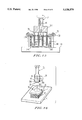
- FIG. 11 is a front view partly cross-sectioned of an embodiment of the grindstone used for the present invention.
- FIG. 12 is a bottom view of the grindstone shown in FIG. 11;
- FIG. 13 is a diagram showing a method of processing disk plate-like materials with use of the grindstone of the present invention.
- FIG. 14 is a diagram showing a state of disk plate-like materials processed with use of the grindstone of the present invention.
- FIGS. 15 and 16 are diagrams showing another method of processing a disk plate-like materials according to the present invention.
- FIG. 1 is a perspective view showing that a plurality of stacked glass plates 10, 10 . . . are placed on a receiving tray 12.
- Each of the glass plates 10 are made of a fragile material and is formed to be a rectangular thin plate. For instance, 50 or 100 glass plates are set up in a stacking state on the receiving tray 12.
- the receiving tray 12 is constituted by a substantially V-like plate 14 with a number of openings 14A, and a pair of side plates 16 for closing both ends of the plate 14.
- the plates 16 are of a triangular shape and are provided with a number of openings 14A in the same manner as the plate 14.
- the dimensions of the length and the height of the receiving tray 12 are respectively determined so that the stacked glass plates 10, 10 . . . can be set up in the receiving tray 12 in a stable manner.
- the receiving tray 12 in which the glass plates 10, 10 . . . are set up is dipped in a bonding liquid 18 (FIG. 3) which is filled in a bucket 20.
- the bonding liquid 18 When the receiving tray 12 is dipped in the bonding liquid 18, the bonding liquid 18 enters into the receiving tray 12 through the openings 14A, 14A . . . . The bonding liquid 18 invades into air gaps between adjacent glass plates 10, 10 in a stacked state, and the bonding liquid 18 spreads throughout the entire air gap regions between the adjacent glass plates 10, 10 due to capillarity. Thus, the bonding liquid are coated on the entire surface of the glass plates 10.
- the thickness of the bonding liquid 18 between the adjacent glass plates 10, 10 can be kept uniform.
- wax or resin curable on irradiation of ultraviolet rays both commercially available
- Wax is softened to become liquid at a predetermined temperature and is solidified at the room temperature.
- the resin usable in the present invention is solidified upon irradiating ultraviolet rays. Accordingly, in a case of using the wax, when a plurality of glass plates 10, 10 . . . stacked in a block form are dipped in the bonding liquid 18 and then, they are drawn up from the bonding liquid 18 so that they are left in the room temperature. The bonding liquid 18 between the glass plates 10, 10 in the stacked glass plates is solidified.
- the glass plates 10, 10 . . . stacked in a block form is dipped in the bonding liquid 18, they are drawn up from the bonding liquid 18 and are subjected to the irradiation of ultraviolet rays, then, the bonding liquid 18 between the glass plates 10, 10 in the stacked glass plates is solidified.
- the adjacent glass plates 10, 10 in the stacked glass plates are joined by the solidified bonding liquid 18.
- bonding layers 18A are formed between the adjacent glass plates 10, 10 in the stacked glass plates in a block form, the glass plates 10, 10 . . . are brought to close-contact with each other in a block form (vide FIGS. 4A and 4B).
- the plurality of glass plates 10, 10 . . . stacked in a block form with the wax can be separated by dipping the stacked glass plates 10, 10 . . . in a releasing liquid.
- the plurality of glass plates 10, 10 . . . stacked in a block form with the UV-cured resin can be separated by the irradiation of ultraviolet rays.
- the UV-cured resin may be capable of melting in boiling water.
- the plurality of glass plates 10, 10 . . . stacked closely in a block form is fixed on the table of a grinding machine by means of an attaching means such as a clamping device, wax vacuum-suction device or freeze chuck.
- an attaching means such as a clamping device, wax vacuum-suction device or freeze chuck.
- An example of the freeze chuck will be described with reference to FIG. 5.
- Peltier elements 24, 24 . . . are embedded in the table 22 of the grinding machine so that they are cooled or heated by switching a voltage to positive and negative sides. Accordingly, the table 22 and the plurality of glass plates 10, 10 . . . stacked closely in a block form can be fixed by freezing water surrounding them, whereby the freeze chuck is effected to the plurality of glass plates 10, 10 . . . stacked in a block form and the table 22.
- the freeze chuck is released, whereby the plurality of glass plates 10, 10 . . . stacked closely in a block form can be removed from the table 22.
- the sucked closely in a block form can be processed with use of, for instance, a grindstone by fixing the glass plates 10, 10 . . . in a block form on the table 22 by means of the freeze chuck. According to this process, the plurality of glass plates 10, 10 . . . can be simultaneously ground.
- the plurality of glass plates 10, 10 . . . stacked in a block form can be separated individually, after the completion of the grinding operation, by dipping the block into the releasing liquid, or by irradiating ultraviolet rays, or by boiling it in a hot water.
- the plurality of glass plates 10, 10 . . . stacked in a block form can be held on the table 22 with a sufficient holding strength which is durable to a load during the processing even when the outer diameter of the glass plates to be processed is small. Accordingly, it is possible to solve the problem of difficulty in the vacuum-sucking of a plurality of rectangular glass plates in a block form in order to process them onto the processing table when the outer diameter of disk-like glass plates to be cut is small or the thickness of the glass plates is less than 0.05 inches.
- FIG. 6 shows a state that a plurality of glass plates 10, 10 . . . stacked closely in a block form are simultaneously perforated.
- FIGS. 7 and 8 show states that circular glass plates 10A, 10A . . . and doughnut-like circular plates 10B, 10B . . . are cut off from a plurality of glass plates 10, 10 . . . stacked closely in a block form.
- the processing of the plurality of the plurality of glass plates 10, 10 . . . stacked closely in a block form can be conducted in the same manner as that a block material is processed, whereby productivity can be improved in comparison with the case that glass plates 10 are processed one by one.
- the plurality of glass plates 10, 10 . . . stacked closely in a block form can greatly reduce a danger of occurrence of the tipping during the processing.
- the tipping may result at the glass plate located at the lowermost portion of the plurality of glass plates 10, 10 . . . stacked closely in a block form.
- a dummy glass plate 37A may be attached to the lower surface of the lowermost glass plate 10 (FIG. 9). In this case, when the circular glass plates 10A, 10A . . . or the doughnut-like circular glass plates 10B, 10B . . .
- the circular glass plates 10A, 10A . . . or the doughnut-like circular glass plates 10b, 10B . . . can be maintained in a state that they are fixed to the dummy glass plate 37A if the dummy glass plate 36 is processed to a certain extent, but not completely processed. In this case, precise cutting operations are possible.
- the dummy plate may be attached onto the uppermost glass plate in addition to the lowermost glass plate in order to eliminate the occurrence of the tipping of the uppermost glass plate.
- the receiving tray 12 with a number of openings is used.
- another receiving tray having cut portions may be used.
- FIGS. 15 and 16 show that a plurality of glass plates 10, 10 . . . are fixed onto a table 41 by using a pressing plate 38 having a central opening which is perforated into a circular shape, bolts 40 and nuts 39.
- FIG. 11 is a front view partly cross-sectioned of a grindstone (core drill) 30 used for the present invention and FIG. 12 is a bottom view of the grindstone 30.
- core drill grindstone
- the grindstone 30 comprises a shaft portion 32, a cylindrical portion 34 and a grindstone portion 36, wherein the shaft portion 32 is detachably attached to the rotating shaft of a grinding machine (not shown).
- the shaft portion 32 is provided with a hole 32A on the same axial line.
- the hole 32A is communicated with a grinding liquid supplying source of the grinding machine when the shaft 32 is attached to the rotating shaft of the machine.
- a flange 32B is formed at an end of the shaft portion 32, and the flange 32B is firmly attached with the upper end of the cylindrical portion 34 so that the cylindrical portion 34 is on the same axial line of the shaft portion 32.
- a spiral groove 34A having a forward thread is formed at the outer periphery of the cylindrical portion 34 while a spiral groove 34B having a reverse thread is formed at the inner periphery of the cylindrical portion 34.
- the forward spiral groove 34A and the reverse spiral groove 34B respectively guide the grinding liquid supplied thereto.
- the grindstone portion 36 is fixed to the lower end portion of the cylindrical portion 34.
- the grindstone portion 36 comprises segment grindstones 36A, 36A . . . which are arranged in an arc form with a predetermined intervals (FIG. 12). Since gaps are formed between adjacent grindstones 36A, 36A, the grinding liquid guided to the segment grindstones 36A, 36A . . . by means of, for instance, the reverse spiral groove 34B is introduced into the spiral groove 34A of forward thread through the gaps between the segment grindstones 36A, 36A.
- the shaft portion 32 of the grindstone 30 is attached to the rotating shaft of the grinding machine so that the hole 32A of the shaft portion 32 is in communication with the grinding liquid supplying source of the grinding machine.
- the grinding liquid is introduced to the inner periphery of the cylindrical portion 34 through the hole 32A.
- the grindstone 32 is clockwisely rotated so that the plurality of glass plate 10, 10 . . . stacked closely in a block form are ground with the segment grindstones 36A, 36A . . .
- the portion of the stacked glass plates to be ground by the segment grindstones 36A, 36A . . . is shallow, the grinding liquid can be easily fed to that portion.
- the portion of the stacked glass plates to be ground with the segment grindstones 36A, 36A . . . becomes deep as shown in FIG. 13.
- the grinding liquid supplied to the inner periphery of the cylindrical portion 34 is introduced downwardly along the spiral groove 34B of reverse thread which is formed at the inner periphery of the cylindrical portion 34, and the liquid reaches the grindstone portion 36 consisting of the segment grindstones 36A, 36A . . . .
- the grinding liquid which has reached the grinding portion 36 is introduced to the outer periphery side of the cylindrical portion 34 through the gaps formed between the segment grindstones 36A, 36A.
- the grinding liquid introduced to the outer periphery side of the cylindrical portion 34 is upwardly guided along the spiral groove 34A of forward thread which is formed at the outer periphery of the cylindrical portion 34, and finally, the liquid is discharged from the outer surface of the glass plate 10 at the top of the stacked glass plates 10, 10 . . . .
- the grinding liquid is supplied to the inner periphery of the cylindrical portion 34.
- the grinding liquid may be supplied to the outer periphery of the cylindrical portion.
- the spiral groove of forward thread is formed at the outer periphery of the cylindrical portion 34 while the spiral groove of reverse thread is formed at the inner periphery.
- the spiral groove of reverse thread may be formed at the outer periphery of the cylindrical portion 34 and the spiral groove of forward thread may be formed at the inner periphery.
- the grindstone is rotated clockwisely.
- the grindstone may be rotated counter clockwisely.
- the upper end of the cylindrical portion 34 is firmly attached to the flange 32B so that the cylindrical portion 34 and the shaft portion 32 are formed in one piece.
- the shaft portion 32 and the cylindrical portion 34 may be formed by cutting a one piece material. In this case, accuracy in coincidence of the axial lines of the shaft portion 32 and the cylindrical portion 34 can be improved.
- the disk-like glass plates are processed by grinding the outer periphery of the glass plates with use of a single core structure (i.e. with use of a circular grindstone 36 for processing the outer periphery).
- doughnut-like glass plates can be processed by grinding simultaneously the inner periphery and the outer periphery by using a double core structure.
- FIGS. 15 and 16 show an embodiment of a grinding machine having the grindstones 36 of such double core structure.
- Outer grindstones 42 arranged in a circular form for processing the outer periphery and inner grindstones 43 arranged in a circular form for processing the inner periphery are provided on the same axis. The grindstone shown in FIGS.
- 15 and 16 is of a structure without the spiral grooves 34A, 34B as shown in FIG. 13. Instead of the spiral grooves, slits 45 are formed in the outer and inner grindstones 42, 43 so that the grinding liquid supplied from the axial bore of the shaft portion 32 reaches the extreme ends of the outer and inner grindstone 42, 43, and then, it is discharged outside.
- glass plates having especially a thickness of 0.05 inches are used as materials to be processed.
- crystallized glass plates, ceramic plates, silicon plates or plates of a fragile material may be used.
- a plurality of plate-like materials are closely stacked into a block form without gaps between adjacent plate-like materials while they are separable; the stacked plate-like materials are processed at once, and then the processed plate-like materials are separated individually. Accordingly, a plurality of late-like material can be simultaneously processed Further, tipping which may result when the plate-like materials are individually processed, can be eliminated.
- bonding layers are formed between the adjacent plate-like materials which are stacked closely in a block form.
- the plate-like materials stacked closely in a block form can be separated individually. Accordingly, the processing operation is easy and productivity can be improved.
- a grinding liquid supplied to the outer periphery or the inner periphery of the cylindrical portion of the grindstone is introduced downwardly to the grinding portion by means of a spiral groove formed in one periphery.
- the grinding liquid introduced to the grinding portion and cuttings can be introduced upwardly by means of a spiral groove formed at the other periphery and they can be discharged outside. Accordingly, the grinding liquid can be sufficiently supplied to the grinding portion when a plurality of disk-like glass plates are processed from a plurality of glass plates stacked closely in a block form.
Landscapes
- Engineering & Computer Science (AREA)
- Mechanical Engineering (AREA)
- Mining & Mineral Resources (AREA)
- Grinding And Polishing Of Tertiary Curved Surfaces And Surfaces With Complex Shapes (AREA)
Abstract
Description
Claims (24)
Applications Claiming Priority (4)
| Application Number | Priority Date | Filing Date | Title |
|---|---|---|---|
| JP4-270292 | 1992-10-08 | ||
| JP27029192 | 1992-10-08 | ||
| JP27029292A JPH06114620A (en) | 1992-10-08 | 1992-10-08 | Grinding wheel and method of processing disk-shaped plate-shaped material using the grinding wheel |
| JP4-270291 | 1992-10-08 |
Publications (1)
| Publication Number | Publication Date |
|---|---|
| US5538579A true US5538579A (en) | 1996-07-23 |
Family
ID=26549148
Family Applications (1)
| Application Number | Title | Priority Date | Filing Date |
|---|---|---|---|
| US08/132,968 Expired - Lifetime US5538579A (en) | 1992-10-08 | 1993-10-07 | Method of processing a plurality of glass plates or the like into a circular shape or a method of perforating a plurality of the same material |
Country Status (1)
| Country | Link |
|---|---|
| US (1) | US5538579A (en) |
Cited By (17)
| Publication number | Priority date | Publication date | Assignee | Title |
|---|---|---|---|---|
| US6176652B1 (en) * | 1999-07-08 | 2001-01-23 | Chunghwa Picture Tubes, Ltd. | Drilling machine with vacuum suction table |
| US6254809B1 (en) * | 1998-05-19 | 2001-07-03 | Steag Hamatech, Inc. | System and method for curing a resin disposed between a top and bottom substrate with thermal management |
| US6275340B1 (en) | 2000-01-21 | 2001-08-14 | Rayford K. Brown | Anesthetic alleviation by sensory stimulation |
| WO2001083180A1 (en) * | 2000-06-21 | 2001-11-08 | Schott Glas | Method for working glass sheets |
| US6363599B1 (en) | 1999-08-04 | 2002-04-02 | Komag, Inc. | Method for manufacturing a magnetic disk including a glass substrate |
| US6669805B2 (en) | 2001-02-16 | 2003-12-30 | International Business Machines Corporation | Drill stack formation |
| US6718612B2 (en) * | 1999-08-04 | 2004-04-13 | Asahi Glass Company, Ltd. | Method for manufacturing a magnetic disk comprising a glass substrate using a protective layer over a glass workpiece |
| US20060061901A1 (en) * | 2004-08-31 | 2006-03-23 | Asahi Glass Company Limited | Glass substrate for magnetic disks |
| US20060117799A1 (en) * | 2004-12-06 | 2006-06-08 | Asahi Glass Company, Limited | Method for coating doughnut-type glass substrates |
| US20060118521A1 (en) * | 2004-12-06 | 2006-06-08 | Asahi Glass Company, Limited | Method for etching doughnut-type glass substrates |
| US20060128154A1 (en) * | 2004-12-15 | 2006-06-15 | Asahi Glass Company, Limited | Glass substrate for magnetic disk and its production process |
| US20060182504A1 (en) * | 2005-01-25 | 2006-08-17 | Asahi Glass Company, Limited | Method for manufacturing a doughnut-shaped glass substrate |
| US20060228997A1 (en) * | 2005-04-07 | 2006-10-12 | Asahi Glass Company, Limited | Apparatus for polishing edge surface of glass substrate for magnetic recording media, and process for producing glass substrate |
| US20090269154A1 (en) * | 2008-04-29 | 2009-10-29 | Seagate Technology Llc | Sheet-stack coring |
| CN101037291B (en) * | 2000-06-21 | 2010-12-22 | 肖特股份公司 | Method and device for manufacturing glass sheets of any profile from flat glass |
| US20170066282A1 (en) * | 2010-06-30 | 2017-03-09 | Flooring Technologies Ltd. | Method for the refinement of a panel and apparatus for carrying out the same |
| US10004498B2 (en) | 2006-01-31 | 2018-06-26 | Ethicon Llc | Surgical instrument comprising a plurality of articulation joints |
Citations (18)
| Publication number | Priority date | Publication date | Assignee | Title |
|---|---|---|---|---|
| US1219461A (en) * | 1915-09-22 | 1917-03-20 | Leo Ries | Circular glass-cutter. |
| US1385732A (en) * | 1916-04-24 | 1921-07-26 | Taylor William | Class-cutting apparatus |
| US1825277A (en) * | 1928-12-21 | 1931-09-29 | Duplate Corp | Process of cutting disks from glass plates |
| US2016159A (en) * | 1931-12-12 | 1935-10-01 | Brown Fayro Company | Apparatus for coating aggregate with binding material |
| US2638084A (en) * | 1951-12-29 | 1953-05-12 | Eli H Mclaughlin | Method and apparatus for drilling glass sheets |
| US2906256A (en) * | 1958-07-08 | 1959-09-29 | Blue Ridge Glass Corp | Method and apparatus for drilling large holes through glass sheets |
| GB827907A (en) * | 1956-11-12 | 1960-02-10 | Oerlikon Maschf | Method of producing a sheet metal packet |
| US3333278A (en) * | 1963-05-31 | 1967-07-25 | Sperry Rand Corp | Method of making frequency responsive device |
| US3749625A (en) * | 1971-08-12 | 1973-07-31 | Gen Motors Corp | Machining process |
| DE2318935A1 (en) * | 1973-04-14 | 1974-10-24 | Dichmann Ag Vario Werke | Slicing veneers efficiently - by bonding log to a plank before cutting |
| US4129093A (en) * | 1977-10-11 | 1978-12-12 | Miles Laboratories, Inc. | Staining apparatus |
| US4167500A (en) * | 1976-06-14 | 1979-09-11 | Lord Corporation | Aqueous compositions comprising phenolic resin and crosslinking agent |
| SU816759A1 (en) * | 1979-06-29 | 1981-04-10 | Предприятие П/Я Г-4119 | Diamond annular drill |
| SU954499A1 (en) * | 1980-12-16 | 1982-08-30 | Организация П/Я Р-6007 | Apparatus for applying metal coatings |
| JPS62107909A (en) * | 1985-11-05 | 1987-05-19 | Disco Abrasive Sys Ltd | Two-blade core drill and manufacture thereof |
| JPS6471238A (en) * | 1987-09-11 | 1989-03-16 | Hitachi Communication System | Fault processing system |
| JPH021773A (en) * | 1988-02-29 | 1990-01-08 | Toto Kasei Kk | Coating composition |
| US5009731A (en) * | 1989-10-25 | 1991-04-23 | Menicon Co., Ltd. | Ultraviolet-hardenable adhesive and bonding method employing same |
-
1993
- 1993-10-07 US US08/132,968 patent/US5538579A/en not_active Expired - Lifetime
Patent Citations (18)
| Publication number | Priority date | Publication date | Assignee | Title |
|---|---|---|---|---|
| US1219461A (en) * | 1915-09-22 | 1917-03-20 | Leo Ries | Circular glass-cutter. |
| US1385732A (en) * | 1916-04-24 | 1921-07-26 | Taylor William | Class-cutting apparatus |
| US1825277A (en) * | 1928-12-21 | 1931-09-29 | Duplate Corp | Process of cutting disks from glass plates |
| US2016159A (en) * | 1931-12-12 | 1935-10-01 | Brown Fayro Company | Apparatus for coating aggregate with binding material |
| US2638084A (en) * | 1951-12-29 | 1953-05-12 | Eli H Mclaughlin | Method and apparatus for drilling glass sheets |
| GB827907A (en) * | 1956-11-12 | 1960-02-10 | Oerlikon Maschf | Method of producing a sheet metal packet |
| US2906256A (en) * | 1958-07-08 | 1959-09-29 | Blue Ridge Glass Corp | Method and apparatus for drilling large holes through glass sheets |
| US3333278A (en) * | 1963-05-31 | 1967-07-25 | Sperry Rand Corp | Method of making frequency responsive device |
| US3749625A (en) * | 1971-08-12 | 1973-07-31 | Gen Motors Corp | Machining process |
| DE2318935A1 (en) * | 1973-04-14 | 1974-10-24 | Dichmann Ag Vario Werke | Slicing veneers efficiently - by bonding log to a plank before cutting |
| US4167500A (en) * | 1976-06-14 | 1979-09-11 | Lord Corporation | Aqueous compositions comprising phenolic resin and crosslinking agent |
| US4129093A (en) * | 1977-10-11 | 1978-12-12 | Miles Laboratories, Inc. | Staining apparatus |
| SU816759A1 (en) * | 1979-06-29 | 1981-04-10 | Предприятие П/Я Г-4119 | Diamond annular drill |
| SU954499A1 (en) * | 1980-12-16 | 1982-08-30 | Организация П/Я Р-6007 | Apparatus for applying metal coatings |
| JPS62107909A (en) * | 1985-11-05 | 1987-05-19 | Disco Abrasive Sys Ltd | Two-blade core drill and manufacture thereof |
| JPS6471238A (en) * | 1987-09-11 | 1989-03-16 | Hitachi Communication System | Fault processing system |
| JPH021773A (en) * | 1988-02-29 | 1990-01-08 | Toto Kasei Kk | Coating composition |
| US5009731A (en) * | 1989-10-25 | 1991-04-23 | Menicon Co., Ltd. | Ultraviolet-hardenable adhesive and bonding method employing same |
Cited By (28)
| Publication number | Priority date | Publication date | Assignee | Title |
|---|---|---|---|---|
| US6511616B1 (en) | 1998-05-19 | 2003-01-28 | Steag Hamatech, Inc. | System and method for curing a resin disposed between a top and bottom substrate with thermal management |
| US6254809B1 (en) * | 1998-05-19 | 2001-07-03 | Steag Hamatech, Inc. | System and method for curing a resin disposed between a top and bottom substrate with thermal management |
| US6176652B1 (en) * | 1999-07-08 | 2001-01-23 | Chunghwa Picture Tubes, Ltd. | Drilling machine with vacuum suction table |
| US6363599B1 (en) | 1999-08-04 | 2002-04-02 | Komag, Inc. | Method for manufacturing a magnetic disk including a glass substrate |
| US6718612B2 (en) * | 1999-08-04 | 2004-04-13 | Asahi Glass Company, Ltd. | Method for manufacturing a magnetic disk comprising a glass substrate using a protective layer over a glass workpiece |
| US6275340B1 (en) | 2000-01-21 | 2001-08-14 | Rayford K. Brown | Anesthetic alleviation by sensory stimulation |
| CN101037291B (en) * | 2000-06-21 | 2010-12-22 | 肖特股份公司 | Method and device for manufacturing glass sheets of any profile from flat glass |
| WO2001098015A3 (en) * | 2000-06-21 | 2002-04-18 | Schott Glas | Method for the production of glass substrates for electronic storage media |
| WO2001099101A3 (en) * | 2000-06-21 | 2002-08-01 | Schott Glas | Method for the production of glass substrates for electronic storage media |
| WO2001083180A1 (en) * | 2000-06-21 | 2001-11-08 | Schott Glas | Method for working glass sheets |
| US7329446B2 (en) | 2001-02-16 | 2008-02-12 | International Business Machines Corporation | Drill stack formation |
| US6669805B2 (en) | 2001-02-16 | 2003-12-30 | International Business Machines Corporation | Drill stack formation |
| US20040086741A1 (en) * | 2001-02-16 | 2004-05-06 | Japp Robert M. | Drill stack formation |
| US20060061901A1 (en) * | 2004-08-31 | 2006-03-23 | Asahi Glass Company Limited | Glass substrate for magnetic disks |
| US20060117799A1 (en) * | 2004-12-06 | 2006-06-08 | Asahi Glass Company, Limited | Method for coating doughnut-type glass substrates |
| US7618895B2 (en) | 2004-12-06 | 2009-11-17 | Asahi Glass Company, Limited | Method for etching doughnut-type glass substrates |
| US20060118521A1 (en) * | 2004-12-06 | 2006-06-08 | Asahi Glass Company, Limited | Method for etching doughnut-type glass substrates |
| US20060128154A1 (en) * | 2004-12-15 | 2006-06-15 | Asahi Glass Company, Limited | Glass substrate for magnetic disk and its production process |
| US7488145B2 (en) | 2005-01-25 | 2009-02-10 | Asahi Glass Company, Limited | Method for manufacturing a doughnut-shaped glass substrate |
| US20060182504A1 (en) * | 2005-01-25 | 2006-08-17 | Asahi Glass Company, Limited | Method for manufacturing a doughnut-shaped glass substrate |
| US20060228997A1 (en) * | 2005-04-07 | 2006-10-12 | Asahi Glass Company, Limited | Apparatus for polishing edge surface of glass substrate for magnetic recording media, and process for producing glass substrate |
| US8021212B2 (en) | 2005-04-07 | 2011-09-20 | Asahi Glass Company, Limited | Apparatus for polishing edge surface of glass substrate for magnetic recording media, and process for producing glass substrate |
| US10004498B2 (en) | 2006-01-31 | 2018-06-26 | Ethicon Llc | Surgical instrument comprising a plurality of articulation joints |
| US20090269154A1 (en) * | 2008-04-29 | 2009-10-29 | Seagate Technology Llc | Sheet-stack coring |
| US8453311B2 (en) * | 2008-04-29 | 2013-06-04 | Seagate Technology Llc | Sheet-stack cutting |
| US20170066282A1 (en) * | 2010-06-30 | 2017-03-09 | Flooring Technologies Ltd. | Method for the refinement of a panel and apparatus for carrying out the same |
| US10226960B2 (en) * | 2010-06-30 | 2019-03-12 | Flooring Technologies Ltd. | Apparatus for the refinement of a panel |
| US11472224B2 (en) | 2010-06-30 | 2022-10-18 | Flooring Technologies Ltd. | Apparatus for the refinement of a panel |
Similar Documents
| Publication | Publication Date | Title |
|---|---|---|
| US5538579A (en) | Method of processing a plurality of glass plates or the like into a circular shape or a method of perforating a plurality of the same material | |
| CN101419936B (en) | Wafer Separation Method | |
| US7348275B2 (en) | Processing method for semiconductor wafer | |
| JP7181020B2 (en) | Wafer processing method | |
| JP2004296935A (en) | Method for manufacturing semiconductor device | |
| JP2009514185A (en) | Die bonding | |
| TWI813674B (en) | Wafer processing method | |
| KR102023203B1 (en) | Machining method | |
| JPH06198530A (en) | Method for processing multiple plate-shaped materials and method for overlapping multiple plate-shaped materials | |
| EP1316992B1 (en) | Method for processing a semiconductor wafer using a laminate substrate as a support for said semiconductor wafer | |
| JP2018207010A (en) | Device chip manufacturing method | |
| US3078549A (en) | Method of producing semiconductor wafers | |
| US20240395620A1 (en) | Wafer processing method | |
| JPH0724725A (en) | Dicing saw and dicing blade | |
| US7462312B2 (en) | Method of fabricating element having microstructure | |
| JPH08290353A (en) | Cutting jig for mono-crystal ingot of semi-conductor | |
| JP6814672B2 (en) | Processing method | |
| JP2019096760A (en) | Wafer processing method | |
| JPH05198671A (en) | Dicing method of semiconductor wafer | |
| US20230377940A1 (en) | Manufacturing method of chips | |
| US20260018464A1 (en) | Method of processing wafer | |
| KR102466383B1 (en) | Device For Glass Plate Treatment | |
| US6632125B2 (en) | Method of manufacturing aluminum frames for photomask protective films | |
| JP2005302798A (en) | BONDING FILM AND METHOD FOR PRODUCING SEMICONDUCTOR CHIP USING BONDING FILM | |
| JPH11288881A (en) | Manufacture of rectangular wafer |
Legal Events
| Date | Code | Title | Description |
|---|---|---|---|
| AS | Assignment |
Owner name: ASAHI GLASS COMPANY LTD., JAPAN Free format text: ASSIGNMENT OF ASSIGNORS INTEREST;ASSIGNORS:ISHIMURA, KAZUHIKO;OZAWA, YOICHI;NAGASAWA, IKUO;AND OTHERS;REEL/FRAME:006830/0577;SIGNING DATES FROM 19931008 TO 19931012 |
|
| STCF | Information on status: patent grant |
Free format text: PATENTED CASE |
|
| FEPP | Fee payment procedure |
Free format text: PAYOR NUMBER ASSIGNED (ORIGINAL EVENT CODE: ASPN); ENTITY STATUS OF PATENT OWNER: LARGE ENTITY |
|
| FPAY | Fee payment |
Year of fee payment: 4 |
|
| AS | Assignment |
Owner name: ASAHI GLASS COMPANY LTD., JAPAN Free format text: CHANGE OF CORPORATE ADDRESS;ASSIGNOR:ASAHI GLASS COMPANY LTD.;REEL/FRAME:010557/0067 Effective date: 19991213 |
|
| FPAY | Fee payment |
Year of fee payment: 8 |
|
| FPAY | Fee payment |
Year of fee payment: 12 |