US2016159A - Apparatus for coating aggregate with binding material - Google Patents
Apparatus for coating aggregate with binding material Download PDFInfo
- Publication number
- US2016159A US2016159A US580532A US58053231A US2016159A US 2016159 A US2016159 A US 2016159A US 580532 A US580532 A US 580532A US 58053231 A US58053231 A US 58053231A US 2016159 A US2016159 A US 2016159A
- Authority
- US
- United States
- Prior art keywords
- binding material
- aggregate
- coating
- basket
- tank
- Prior art date
- Legal status (The legal status is an assumption and is not a legal conclusion. Google has not performed a legal analysis and makes no representation as to the accuracy of the status listed.)
- Expired - Lifetime
Links
- 239000011248 coating agent Substances 0.000 title description 77
- 238000000576 coating method Methods 0.000 title description 77
- 239000000463 material Substances 0.000 title description 71
- 239000012615 aggregate Substances 0.000 description 63
- 244000309464 bull Species 0.000 description 14
- 238000007654 immersion Methods 0.000 description 11
- 239000013049 sediment Substances 0.000 description 3
- UIQWBVPFHHQZHH-UHFFFAOYSA-N OOOOOOOOOOOOOO Chemical compound OOOOOOOOOOOOOO UIQWBVPFHHQZHH-UHFFFAOYSA-N 0.000 description 2
- 239000000839 emulsion Substances 0.000 description 2
- 238000010438 heat treatment Methods 0.000 description 2
- JWOLLWQJKQOEOL-UHFFFAOYSA-N OOOOOOOOOOOOO Chemical compound OOOOOOOOOOOOO JWOLLWQJKQOEOL-UHFFFAOYSA-N 0.000 description 1
- 238000013459 approach Methods 0.000 description 1
- 239000010426 asphalt Substances 0.000 description 1
- 239000011230 binding agent Substances 0.000 description 1
- 239000011280 coal tar Substances 0.000 description 1
- 230000003247 decreasing effect Effects 0.000 description 1
- 230000000694 effects Effects 0.000 description 1
- 238000007689 inspection Methods 0.000 description 1
- 239000007788 liquid Substances 0.000 description 1
- 238000000034 method Methods 0.000 description 1
- 238000005086 pumping Methods 0.000 description 1
- 230000000979 retarding effect Effects 0.000 description 1
- 239000007787 solid Substances 0.000 description 1
- 239000002904 solvent Substances 0.000 description 1
Images


Classifications
-
- E—FIXED CONSTRUCTIONS
- E01—CONSTRUCTION OF ROADS, RAILWAYS, OR BRIDGES
- E01C—CONSTRUCTION OF, OR SURFACES FOR, ROADS, SPORTS GROUNDS, OR THE LIKE; MACHINES OR AUXILIARY TOOLS FOR CONSTRUCTION OR REPAIR
- E01C19/00—Machines, tools or auxiliary devices for preparing or distributing paving materials, for working the placed materials, or for forming, consolidating, or finishing the paving
- E01C19/02—Machines, tools or auxiliary devices for preparing or distributing paving materials, for working the placed materials, or for forming, consolidating, or finishing the paving for preparing the materials
- E01C19/10—Apparatus or plants for premixing or precoating aggregate or fillers with non-hydraulic binders, e.g. with bitumen, with resins, i.e. producing mixtures or coating aggregates otherwise than by penetrating or surface dressing; Apparatus for premixing non-hydraulic mixtures prior to placing or for reconditioning salvaged non-hydraulic compositions
- E01C19/1013—Plant characterised by the mode of operation or the construction of the mixing apparatus; Mixing apparatus
- E01C19/1018—Coating the solid ingredients by immersion in a bath of binder
Definitions
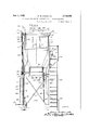
- Figure l is a side elevation of the whole apparatus
- Figure 2 is a front elevation
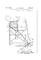
- Figure 3 is a vertical section on the line III- III of Figure 2;
- Figure 4 is a horizontal section taken in a plane corresponding to the line IV-IV of Figure 1;
- Figure 5 is a sectional View illustrating the basket used for coating the aggregate
- Figure 6 is a detail sectional view of the .gate used for controlling flow of coated aggregate from the storage bin.
- a coating tank 4, and a bin 5 in which the aggregate is further coated, drained, and stored are mounted adjacent the upper end of the framework, the coating tank being provided with steam coils 6 supplied with steam through a pipe I connected to a suitable source of steam supply.
- a shaft I0 extends transversely of the coating tank and storage bin and is disposed slightly above these elements. As shown in Figure 2, adjacent each end of the shaft is a bearing I I having a sleeve portion I2 keyed to the shaft, and an arm I3. Next to the bearing II is a bearing Ila secured to the framework. A perforated basket I4 is secured to the arms I3 by fastening Y means I5, shown in Figure-3, the shaft in this manner supporting the basket so that when the shaft is rotated the basket is raised from or lowered into the coating tank.
- the shaft I3 carriesV at one end a bull wheel I1 which is keyed to the shaft.
- the bull Wheel is rotated by means of a drum and rope in the following manner:
- the power unit for rotating the bull wheel II and which is, therefore, operative to withdraw the basket I4 from the coating tank, is shown in Figures l and 4.
- a sprocket chain 20 passes around a sprocket 2
- the friction clutch is operated by a handle 21 for rotating a drum 28 about which a rope 29 is wound and unwound in order to rotate the bull wheel I1. 5
- the friction clutch is not described in greater detail since any suitable type of friction clutch may be employed. It is preferred, however, to employ a clutch of the general type shown in Patent No. 1,352,653, granted September 14, 1920, 10 to Herbert V. Brown, since this type of clutch has been found particularly adapted to thepresent use.
- the rope 29 passes over one of the two sheaves 33 mounted in a block 3
- the rope 29 then passes upwardly and around the other sheave 30 of the double sheave and then downwardly and is fixed, as indicated by the reference numeral 34, to the brace 33 secured to 2o i the framework of the apparatus.
- the block 3l is suspended by a rope 35 which passes around the bull wheel Il and is adjustably secured to the bull wheel in any of the positions indicated by the reference numeral 38.
- Another rope 39, 25 which may if desired be simply a continuation of the rope 36, is secured to the bull wheel I'I at one of the points 38 and passes downwardly around a sheave 40 mounted in the brace 33.
- the lower end of the rope 39 carries a counterweight 42 30V which is guided in a housing 43 by providing flanges 44 which cooperate with corresponding grooves in the counterweight.
- Binding material is withdrawn from a storage tank (not shown) through a pipe 53, shown in Figure 1, by a pump 5I. 'I'he pump is operated through a sprocket chain 52 which 40 passes around sprockets 53 and 54 secured, respectively, to thepump shaftand theengine shaft. After passing through the pump 5I, the binding Vmaterial ows through an inlet pipe 55 controlled by a valve 50 and is delivered adjacent the bot- 45 tom of the coating tank 4.
- An overflow pipe 51 which has a plurality ⁇ of connections 58 and 59 to the coating tank 4, is provided for taking care of the overflow of binding material, an excess of the binding material being supplied by the pump 50 5I in order to maintain the desired level in the coating tank at all times.
- the overflow passes through the pipe 5l' and is returned to a storage tank (not shown).
- One of the connections 58 or 5S may be plugged up in order to vary the level 5 5 of the binding material in the coating tank.
- the gate 69 is secured at oneedge to a pipe 6
- link 65 is pivotally connected at its upper end to the gate 60 and at its lower end to a bell crank lever 66 which is pivoted to the framework of the apparatus, as indicated by the'reference numeral 61.
- the bell crank 66 is actuated by the operator through a rod 68 provided with a handle
- a counterweight 'Ill is adjustably mounted on the armr 'H of the bell crank 66 in order to render the opening and closing of the gate easy.
- the gate is-closed by the operator pulling downwardly on the handle 69, which lowers the arm 'II and raises the link 65, therebylmoving the gate E!) from its chain-line to its full-line position of Figure
- The-gate is ⁇ shown in closed position in Figure 3 and also in FigureV 6, from which it will be seenY that even when the gate is closed so as to prevent delivery or" coated aggregate from the bin 5, there -is a space 'I5 between the gate 60 and the lower edge 'I6 of the storage 4bin 5 which allows excess ⁇ binding material to drain through the space 'I5 and flow over the portion 'I'I of the pipe 6
- the binding material thus drained from the coated aggregate in the Vstorage bin is deflected by a flange V'I8 into a trough 79 and is returned to the storage tank by a pipeil.
- the trough 'I9 is provided with a weir 8
- the binding materialV co1- lected in the settling basin is delivered through a pipe 8l controlled by a valve 98 to a sediment receptacle 89.
- the perforated basket I4 used for coating the agg-regate in the coating tank 4 is illustrated inv Figure 5.V It is provided with perforations 95 which allow the binding material to enter the basket and coat the aggregate.
- the basket instead of being continuous throughout its length, is divided into several compartments 96 by pock- The binding material may iiow freely into these pockets and then through the perforations 95 so as to insure positive coating of the aggregate irrespec- Vtive of its position in the basket.
- the aggregate to be coated is delivered to the coating tank 4 by any desired means, for example, through a chute 94 or from a bucket, the aggregate-being guided into the coating tank by a hopper 98 arranged at the top of the tank and provided with ribs or guide plates 99 which act-to evenly distribute the aggregate in the basket I4.
- the counterweight acts to return the basket to the coating tank so that after the l aggregate has been delivered to the storage bin 5 Vand the operator releases the brake, the counterweight causes the bull wheel II and the basket E4 to rotate counter-clockwise, thereby lowering the basket into the coating tank.
- the basket 2Q passes from its upper position outside of the tank to its lower position within the tank, the point of connection of the rope 39 to the bull wheel I'I moves counter-clockwise from the point
- the action of the counterweight is to aid in returning the basket to the coating tank.
- the point of attachment of the rope 39 to the bull wheel passes Vthe point
- counterweight is to retard the lowering of the basket.
- the action of the counterweight acts to cushion the lowering of the basket into the immersion tank, thereby decreasing splashing and danger o overflow.
- the coated aggregate dumped from the basket if tumbles about as it is delivered to the storage bin 5 and as it flows downwardly toward the gate 6s so that positive coating of the aggregate is insured. yThe excess aggregate is returned to the storage tank fromrthe trough E9 by the pipe 80, as previously described, so that when the gate is opened andthe coated aggregate is delivered to a truck, there is no excess of binding material on the aggregate.
- the amount o-f coating applied to the aggregate can be varied by varying the speed at which the basket is raised from the coating tank.
- a .relatively large amount of binding material is trapped in the aggregate and dumped therewith in to the bin 5.
- the coating of the aggregate will be somewhat heavier than if less binding material had been trapped with the aggregate delivered to the storage bin.
- the basket is raised slowly, most of the excess binding material has an opportunity Vto drain from the basket before the aggregate is delivered to the storage bin and the coating will, accordingly, be relatively thin.
- the apparatus and method are adapted for use V.either with emulsionsrof binding material, or with cut-backs in which a solid binder such as asphalt or coal tar is at least partially dissolved byY a solvent to form the liquid binding material.
- the heating coils G in the coating tankV are provided so that cut-backs, as well as emulsions, may be used. Steam or other heating means may be applied to the coils toimpart the desired fluidity to the binding material, but this is usually necessary only in the use of cutbacks, and not with emulsions.
- a ladder 595 is provided for-gaining access to'75 an inspection platform
- a coating, drainage and storage bin for the coated aggregate for the coated aggregate, a gate controlling delivery of the aggregate from the bin, and means for operating the gate, said gate providing means for draining excess binding material from the coated aggregate in said bin.
- Apparatus for coating aggregate with binding material comprising a coating tank adapted to receive binding material, a perforated basket mounted for immersion in and withdrawal from the binding material in the coating tank, said basket being secured tot a shaft, and means for rotating the shaft to raise and lower the basket.
- Apparatus for coating aggregate with binding material comprising a coating tank adapted to receive binding material, a perforated basket mounted for immersion in and withdrawal from the binding material in the coating tank, said basket being secured to a shaft, a wheel secured to the shaft, and power means operatively connected to the wheel for raising and lowering the basket.
- Apparatus for coating aggregate with binding material comprising a coating tank adapted to receive binding material, a perforated basket mounted for immersion in and withdrawal from the binding material in the coating tank, said basket being secured to a shaft, a wheel secured to the shaft, and a rope drive operatively connected to the wheel for raising and lowering the basket.
- Apparatus for coating aggregate with binding material comprising a coating tank adapted to receive binding material, a perforated basket mounted for immersion in and withdrawal from the binding material in the coating tank, power means for raising the basket from the coating tank, and a counterweight operatively connected to the basket, the counterweight being eifective for aiding the initial lowering and for retarding the subsequent lowering of the basket into the coating tank.
- Apparatus for coating aggregate with binding material comprising a coating tank adapted to receive binding material, a perforated basket mounted for immersion in and Withdrawal from Ithe binding material in the coating tank, said basket being secured to a shaft, a wheel secured to the shaft, means for rotating the wheel to raise and lower the basket, and a counterweight connected to the wheel, the counterweight being effective for aiding the initial lowering and forretarding the subsequent lowering of the basket into the coating tank.
- Apparatus for coating aggregate with binding material comprising a coating tank adapted to receive binding material, a perforated basket mounted for immersion in and withdrawal from the binding material in the coating tank, said basket being secured to a shaft, a wheel secured to the shaft, power means operatively connected to the wheel for raising and lowering the basket, and a counterweight connected to the wheel, the point of connection of the counterweight to the Wheel being such that as the basket approaches its lowest position within the tank the counterweight acts to retard the lowering of the basket.
- Apparatus for coating aggregate with binding material comprising a coating tank adapted to receive binding material, a perforated basket mounted for immersion in and withdrawal from the binding material, a stationary coating, drainage and storage bin adjacent the coating tank, means for delivering coated aggregate from the basket to said bin, means for supplying the coating tank with binding material, and means for draining and removing excess binding material from the coated aggregate in said bin.
- Apparatus for coating aggregate with binding material comprising a coating tank adapted to receive binding material, a perforated basket mounted for immersion in and withdrawal from the binding material, a stationary coating, drainage and storage bin adjacent the coating tank, means for delivering coated aggregate from the basket to said bin, a settling basin adjacent the bottom of the coating tank, and means for withdrawing sediment from the settling basin.
- Apparatus for coating aggregate with binding material comprising a coating tank adapted to receive binding material, a perforated basket mounted for immersion in and withdrawal from the binding material, a coating, drainage and storage bin adjacent the coating tank, means for delivering coated aggregate from the basket to said bin, a gate for controlling delivery of coated aggregate from the storage bin, a trough adjacent the gate, said gate acting to deflect excess binding material into the trough, and means for returning the collected excess binding material to a storage tank.
- Apparatus for coating aggregate with binding material comprising a coating tank, a coating, drainage and storage bin for coated aggregate, a perforated basket mounted for immersion in and withdrawal from the binding material and adapted to deliver coated aggregate to said bin, a pump and means for operating the same, a binding material storage tank, means for pumping binding material from the storage tank to the coating tank, an overflow pipe connecting the coating tank and storage tank, means for operating said basket, and means for removing excess binding material from the coated aggregate in the storagev bin and returning it to the storage tank.
- a coating, drainage and storage bin for receiving coated aggregate containing an excess of binding material, a gate adjacent the delivery end of the storage bin for controlling delivery oi the aggregate, said gate being rotatably mounted and when in closed position spaced from the end of the bin a distance less than the diameter of the aggregate so as to prevent delivery of aggregate but cause draining of excess binding material from the storage bin.
- a coating, drainage and storage bin for receiving coated aggregate containing an excess of binding material
- a gate adjacent the delivery end of the storage bin for controlling delivery of the aggregate, said gate being rotatably mounted and when in closed position spaced from the end of the bin a distance less than the diameter of the aggregate soas to prevent delivery of aggregate but cause draining of excess binding material from the storage bin, a trough adjacent the gate, and means for deecting the excess binding material into the trough.
Landscapes
- Engineering & Computer Science (AREA)
- Architecture (AREA)
- Civil Engineering (AREA)
- Structural Engineering (AREA)
- Coating Apparatus (AREA)
Description
Oct.` l, 1935.V Gg'wqwARMoTH 2,916,159
APPARATUS FOR COATING GGREGATE WITH BINDING MATERIAL Filed Dec. ll2, 1931 4 SheeLs-Sheetl l A Oct. 1, 1935. G. w. wARMoTH 2,016,159
APPARATUS FOR COATING AGGREGATE WITH BINDING MATERIAL Filed Deo. l2, 1931 4 Sheets-Sheet 2 INVENTOR e( 074 M fw Oct. l, 1935.
G. w. wARMoTH APPARATUS FOR COATING AGGREGATE WITH BINDING MATERIAL Filed Deo. l2, 1931 4 Sheets-Sheet 5 INVENTQR- APPARATUS FOR COATING AGGREGATE WITH BINDING MATERIAL Oct. l, 1935.. G. W. WARMOTH y 4 Sheets-Sheet 4 Filed Deo.
ooooooooooooo, ooooooooeoookoo ou oooooooooooooo oooooooooooooo oooeoooooooooo. oooooooooooooo @0000060090000 INVENTOR Patented Oct. 1, 1935 UNITED STATES V Y 2,016,159 PATENT GFFICE APPARATUS FOR COATING AGGREGATE WITH BINDING MATERIAL George W. Warmoth, Indianapolis, Ind., assignor, by mesne assignments, to The Brown-Fayro Company, Johnstown, Pa., a corporation o Pennsylvania Application December 12, 1931, Serial No. 580,532
13 Claims. (Cl. 94-43) lbinding material is allowed to drain from the coated aggregate and is returned to a storage tank. A gate is provided at the delivery end of the storage bin so that delivery of the coated aggregate to a truck may be interrupted.
In the accompanying drawings, which illustrate the present preferred form of my invention,
Figure l is a side elevation of the whole apparatus;
Figure 2 is a front elevation;
Figure 3 is a vertical section on the line III- III of Figure 2;
Figure 4 is a horizontal section taken in a plane corresponding to the line IV-IV of Figure 1;
Figure 5 is a sectional View illustrating the basket used for coating the aggregate, and
Figure 6 is a detail sectional view of the .gate used for controlling flow of coated aggregate from the storage bin.
Referring more particularly to the accompanying drawings, there is provided a framework of general rectangular shape formed by angle corner posts 2 and cross brace angles 3. A coating tank 4, and a bin 5 in which the aggregate is further coated, drained, and stored are mounted adjacent the upper end of the framework, the coating tank being provided with steam coils 6 supplied with steam through a pipe I connected to a suitable source of steam supply.
A shaft I0 extends transversely of the coating tank and storage bin and is disposed slightly above these elements. As shown in Figure 2, adjacent each end of the shaft is a bearing I I having a sleeve portion I2 keyed to the shaft, and an arm I3. Next to the bearing II is a bearing Ila secured to the framework. A perforated basket I4 is secured to the arms I3 by fastening Y means I5, shown in Figure-3, the shaft in this manner supporting the basket so that when the shaft is rotated the basket is raised from or lowered into the coating tank.
The shaft I3 carriesV at one end a bull wheel I1 which is keyed to the shaft. The bull Wheel is rotated by means of a drum and rope in the following manner:
The power unit for rotating the bull wheel II and which is, therefore, operative to withdraw the basket I4 from the coating tank, is shown in Figures l and 4. A sprocket chain 20 passes around a sprocket 2| secured to a shaft 22 of a gasoline engine 23, and also over a sprocket 24 secured to a shaft 25 of a friction clutch indicated generally by the reference numeral 26. The friction clutch is operated by a handle 21 for rotating a drum 28 about which a rope 29 is wound and unwound in order to rotate the bull wheel I1. 5
The friction clutch is not described in greater detail since any suitable type of friction clutch may be employed. It is preferred, however, to employ a clutch of the general type shown in Patent No. 1,352,653, granted September 14, 1920, 10 to Herbert V. Brown, since this type of clutch has been found particularly adapted to thepresent use. A
The rope 29 passes over one of the two sheaves 33 mounted in a block 3|, and then downwardly 15 and around a sheave 32 trunnioned in a brace 33. The rope 29 then passes upwardly and around the other sheave 30 of the double sheave and then downwardly and is fixed, as indicated by the reference numeral 34, to the brace 33 secured to 2o i the framework of the apparatus. The block 3l is suspended by a rope 35 which passes around the bull wheel Il and is adjustably secured to the bull wheel in any of the positions indicated by the reference numeral 38. Another rope 39, 25 which may if desired be simply a continuation of the rope 36, is secured to the bull wheel I'I at one of the points 38 and passes downwardly around a sheave 40 mounted in the brace 33. The lower end of the rope 39 carries a counterweight 42 30V which is guided in a housing 43 by providing flanges 44 which cooperate with corresponding grooves in the counterweight.
The connections for supplying thefcoating tank 4 with binding material and for withdrawing sur- 35 plus binding material from the coated aggregate are as follows: Binding material is withdrawn from a storage tank (not shown) through a pipe 53, shown in Figure 1, by a pump 5I. 'I'he pump is operated through a sprocket chain 52 which 40 passes around sprockets 53 and 54 secured, respectively, to thepump shaftand theengine shaft. After passing through the pump 5I, the binding Vmaterial ows through an inlet pipe 55 controlled by a valve 50 and is delivered adjacent the bot- 45 tom of the coating tank 4. An overflow pipe 51 which has a plurality `of connections 58 and 59 to the coating tank 4, is provided for taking care of the overflow of binding material, an excess of the binding material being supplied by the pump 50 5I in order to maintain the desired level in the coating tank at all times. The overflow passes through the pipe 5l' and is returned to a storage tank (not shown). One of the connections 58 or 5S may be plugged up in order to vary the level 5 5 of the binding material in the coating tank.
As will be described more fully hereinafter, rotation of the bull wheel I'I raises the basket I4 containing coated aggregate from the coating tank 4 anddeposits it in the storage bin 5. The 60 a gate B9, shown more particularly in Figures" 1,`V
3 and 6. The gate 69 is secured at oneedge to a pipe 6| mounted for rotation on a-shaft- 62 secured to plates 63 on the storage bin, and is lopened and Vclosed manually byV the operator. A
link 65 is pivotally connected at its upper end to the gate 60 and at its lower end to a bell crank lever 66 which is pivoted to the framework of the apparatus, as indicated by the'reference numeral 61. The bell crank 66 is actuated by the operator through a rod 68 provided with a handle |59.V A counterweight 'Ill is adjustably mounted on the armr 'H of the bell crank 66 in order to render the opening and closing of the gate easy. The gate is-closed by the operator pulling downwardly on the handle 69, which lowers the arm 'II and raises the link 65, therebylmoving the gate E!) from its chain-line to its full-line position of Figure The-gate is` shown in closed position in Figure 3 and also in FigureV 6, from which it will be seenY that even when the gate is closed so as to prevent delivery or" coated aggregate from the bin 5, there -is a space 'I5 between the gate 60 and the lower edge 'I6 of the storage 4bin 5 which allows excess` binding material to drain through the space 'I5 and flow over the portion 'I'I of the pipe 6|. The binding material thus drained from the coated aggregate in the Vstorage bin is deflected by a flange V'I8 into a trough 79 and is returned to the storage tank by a pipeil. The trough 'I9 is provided with a weir 8| which prevents sediment from,r being returned to the storage tank.
, binding material.
may be cleaned out. The binding materialV co1- lected in the settling basin is delivered through a pipe 8l controlled by a valve 98 to a sediment receptacle 89.
The perforated basket I4 used for coating the agg-regate in the coating tank 4 is illustrated inv Figure 5.V It is provided with perforations 95 which allow the binding material to enter the basket and coat the aggregate. The basket, instead of being continuous throughout its length, is divided into several compartments 96 by pock- The binding material may iiow freely into these pockets and then through the perforations 95 so as to insure positive coating of the aggregate irrespec- Vtive of its position in the basket.
YThe aggregate to be coated is delivered to the coating tank 4 by any desired means, for example, through a chute 94 or from a bucket, the aggregate-being guided into the coating tank by a hopper 98 arranged at the top of the tank and provided with ribs or guide plates 99 which act-to evenly distribute the aggregate in the basket I4.
l28 and the bull wheel I'I, causes the bull wheel to be rotated and the basket to be lifted from the tank 4. As the basket is raised, the bull wheel rotates in a clockwise direction, as viewed in Figjure l, the rotation of the basket being limited by 5 .stops IIl with which the leading edges IUI of the basket contact. While the basket is being rotated into its chain-line position shown in Figure l iniorderY to dump the coated aggregate into the storage bin 5, the point of connection 38 of l0 the rope 39,'to which the counterweight 42 is attached, rotates clockwise until it assumes the position indicated bythe reference numeral |02. In this position, the counterweight acts to return the basket to the coating tank so that after the l aggregate has been delivered to the storage bin 5 Vand the operator releases the brake, the counterweight causes the bull wheel II and the basket E4 to rotate counter-clockwise, thereby lowering the basket into the coating tank. As the basket 2Q passes from its upper position outside of the tank to its lower position within the tank, the point of connection of the rope 39 to the bull wheel I'I moves counter-clockwise from the point |02` to the point 3B. As the point |02 moves downwardly to a position |93 directly under the shaft I0, the action of the counterweight is to aid in returning the basket to the coating tank. However, as the point of attachment of the rope 39 to the bull wheel passes Vthe point |93, the effect of the ,30,l
counterweight is to retard the lowering of the basket. The action of the counterweight acts to cushion the lowering of the basket into the immersion tank, thereby decreasing splashing and danger o overflow. Y
The coated aggregate dumped from the basket if tumbles about as it is delivered to the storage bin 5 and as it flows downwardly toward the gate 6s so that positive coating of the aggregate is insured. yThe excess aggregate is returned to the storage tank fromrthe trough E9 by the pipe 80, as previously described, so that when the gate is opened andthe coated aggregate is delivered to a truck, there is no excess of binding material on the aggregate.
Y The amount o-f coating applied to the aggregate can be varied by varying the speed at which the basket is raised from the coating tank. Thus, if the basket raised quickly, a .relatively large amount of binding material is trapped in the aggregate and dumped therewith in to the bin 5. Although some of the excess of binding material will separatefrom the aggregate in the storage bin, the coating of the aggregate will be somewhat heavier than if less binding material had been trapped with the aggregate delivered to the storage bin. On the other hand, if the basket is raised slowly, most of the excess binding material has an opportunity Vto drain from the basket before the aggregate is delivered to the storage bin and the coating will, accordingly, be relatively thin. The apparatus and method are adapted for use V.either with emulsionsrof binding material, or with cut-backs in which a solid binder such as asphalt or coal tar is at least partially dissolved byY a solvent to form the liquid binding material. The heating coils G in the coating tankV are provided so that cut-backs, as well as emulsions, may be used. Steam or other heating means may be applied to the coils toimpart the desired fluidity to the binding material, but this is usually necessary only in the use of cutbacks, and not with emulsions. Y
A ladder 595 is provided for-gaining access to'75 an inspection platform |06 so that the operation of the device may be seen and the settling basin may be cleaned.
I have illustrated and described the present preferred embodiment of my invention. It is to be understood, however, that the invention may be otherwise embodied or practiced within the scope of the following claims.
I claim:
1. In apparatus for coating aggregate with binding material, a coating, drainage and storage bin for the coated aggregate, a gate controlling delivery of the aggregate from the bin, and means for operating the gate, said gate providing means for draining excess binding material from the coated aggregate in said bin.
2. Apparatus for coating aggregate with binding material, comprising a coating tank adapted to receive binding material, a perforated basket mounted for immersion in and withdrawal from the binding material in the coating tank, said basket being secured tot a shaft, and means for rotating the shaft to raise and lower the basket.
3. Apparatus for coating aggregate with binding material, comprising a coating tank adapted to receive binding material, a perforated basket mounted for immersion in and withdrawal from the binding material in the coating tank, said basket being secured to a shaft, a wheel secured to the shaft, and power means operatively connected to the wheel for raising and lowering the basket.
4. Apparatus for coating aggregate with binding material, comprising a coating tank adapted to receive binding material, a perforated basket mounted for immersion in and withdrawal from the binding material in the coating tank, said basket being secured to a shaft, a wheel secured to the shaft, and a rope drive operatively connected to the wheel for raising and lowering the basket.
5. Apparatus for coating aggregate with binding material, comprising a coating tank adapted to receive binding material, a perforated basket mounted for immersion in and withdrawal from the binding material in the coating tank, power means for raising the basket from the coating tank, and a counterweight operatively connected to the basket, the counterweight being eifective for aiding the initial lowering and for retarding the subsequent lowering of the basket into the coating tank.
6. Apparatus for coating aggregate with binding material, comprising a coating tank adapted to receive binding material, a perforated basket mounted for immersion in and Withdrawal from Ithe binding material in the coating tank, said basket being secured to a shaft, a wheel secured to the shaft, means for rotating the wheel to raise and lower the basket, and a counterweight connected to the wheel, the counterweight being effective for aiding the initial lowering and forretarding the subsequent lowering of the basket into the coating tank. V 7. Apparatus for coating aggregate with binding material, comprising a coating tank adapted to receive binding material, a perforated basket mounted for immersion in and withdrawal from the binding material in the coating tank, said basket being secured to a shaft, a wheel secured to the shaft, power means operatively connected to the wheel for raising and lowering the basket, and a counterweight connected to the wheel, the point of connection of the counterweight to the Wheel being such that as the basket approaches its lowest position within the tank the counterweight acts to retard the lowering of the basket.
8. Apparatus for coating aggregate with binding material, comprising a coating tank adapted to receive binding material, a perforated basket mounted for immersion in and withdrawal from the binding material, a stationary coating, drainage and storage bin adjacent the coating tank, means for delivering coated aggregate from the basket to said bin, means for supplying the coating tank with binding material, and means for draining and removing excess binding material from the coated aggregate in said bin.
9. Apparatus for coating aggregate with binding material, comprising a coating tank adapted to receive binding material, a perforated basket mounted for immersion in and withdrawal from the binding material, a stationary coating, drainage and storage bin adjacent the coating tank, means for delivering coated aggregate from the basket to said bin, a settling basin adjacent the bottom of the coating tank, and means for withdrawing sediment from the settling basin.
l0. Apparatus for coating aggregate with binding material, comprising a coating tank adapted to receive binding material, a perforated basket mounted for immersion in and withdrawal from the binding material, a coating, drainage and storage bin adjacent the coating tank, means for delivering coated aggregate from the basket to said bin, a gate for controlling delivery of coated aggregate from the storage bin, a trough adjacent the gate, said gate acting to deflect excess binding material into the trough, and means for returning the collected excess binding material to a storage tank.
ll. Apparatus for coating aggregate with binding material, comprising a coating tank, a coating, drainage and storage bin for coated aggregate, a perforated basket mounted for immersion in and withdrawal from the binding material and adapted to deliver coated aggregate to said bin, a pump and means for operating the same, a binding material storage tank, means for pumping binding material from the storage tank to the coating tank, an overflow pipe connecting the coating tank and storage tank, means for operating said basket, and means for removing excess binding material from the coated aggregate in the storagev bin and returning it to the storage tank.
12. In apparatus for coating aggregate with binding material, a coating, drainage and storage bin for receiving coated aggregate containing an excess of binding material, a gate adjacent the delivery end of the storage bin for controlling delivery oi the aggregate, said gate being rotatably mounted and when in closed position spaced from the end of the bin a distance less than the diameter of the aggregate so as to prevent delivery of aggregate but cause draining of excess binding material from the storage bin.
13. In apparatus for coating aggregate with binding material, a coating, drainage and storage bin for receiving coated aggregate containing an excess of binding material, a gate adjacent the delivery end of the storage bin for controlling delivery of the aggregate, said gate being rotatably mounted and when in closed position spaced from the end of the bin a distance less than the diameter of the aggregate soas to prevent delivery of aggregate but cause draining of excess binding material from the storage bin, a trough adjacent the gate, and means for deecting the excess binding material into the trough.
GEORGE W. WARMOTH.
Priority Applications (1)
| Application Number | Priority Date | Filing Date | Title |
|---|---|---|---|
| US580532A US2016159A (en) | 1931-12-12 | 1931-12-12 | Apparatus for coating aggregate with binding material |
Applications Claiming Priority (1)
| Application Number | Priority Date | Filing Date | Title |
|---|---|---|---|
| US580532A US2016159A (en) | 1931-12-12 | 1931-12-12 | Apparatus for coating aggregate with binding material |
Publications (1)
| Publication Number | Publication Date |
|---|---|
| US2016159A true US2016159A (en) | 1935-10-01 |
Family
ID=24321484
Family Applications (1)
| Application Number | Title | Priority Date | Filing Date |
|---|---|---|---|
| US580532A Expired - Lifetime US2016159A (en) | 1931-12-12 | 1931-12-12 | Apparatus for coating aggregate with binding material |
Country Status (1)
| Country | Link |
|---|---|
| US (1) | US2016159A (en) |
Cited By (1)
| Publication number | Priority date | Publication date | Assignee | Title |
|---|---|---|---|---|
| US5538579A (en) * | 1992-10-08 | 1996-07-23 | Asahi Glass Company Ltd. | Method of processing a plurality of glass plates or the like into a circular shape or a method of perforating a plurality of the same material |
-
1931
- 1931-12-12 US US580532A patent/US2016159A/en not_active Expired - Lifetime
Cited By (1)
| Publication number | Priority date | Publication date | Assignee | Title |
|---|---|---|---|---|
| US5538579A (en) * | 1992-10-08 | 1996-07-23 | Asahi Glass Company Ltd. | Method of processing a plurality of glass plates or the like into a circular shape or a method of perforating a plurality of the same material |
Similar Documents
| Publication | Publication Date | Title |
|---|---|---|
| US3203631A (en) | Abrasive type roof coating apparatus | |
| US2016159A (en) | Apparatus for coating aggregate with binding material | |
| US3142639A (en) | Apparatus and process for neutralizing acid mine drainage water | |
| US2844264A (en) | Apparatus for handling shortening or like material | |
| US2295437A (en) | Sampling device | |
| US3421626A (en) | Sewage treatment systems including an aerating reservoir and a post-sedimentation reservoir supplied from said aerating reservoir | |
| US2189222A (en) | Apron control for carrying scrapers | |
| US2137051A (en) | Apparatus for the lixiviation of mineral ores | |
| US2662642A (en) | Screw dewatering classifier | |
| US2033213A (en) | Sedimentation apparatus | |
| US580561A (en) | John foster stepiienson | |
| US1738211A (en) | Material-moving apparatus | |
| US1572864A (en) | Tapping trough, slag sweeper or skimmer | |
| US1434597A (en) | Settling apparatus | |
| US2057208A (en) | Apparatus for salting water | |
| JPS5817607Y2 (en) | Sand raking machine | |
| US1737115A (en) | Cleaning machine | |
| USRE17875E (en) | haines | |
| US1776371A (en) | Automatic flood gate | |
| US1525622A (en) | Gravel washer | |
| US2053636A (en) | Settling tank | |
| US1838563A (en) | Automatic stock regulator for paper machines | |
| US1546911A (en) | Power appabatus | |
| US1448262A (en) | Device for water distribution | |
| US1201499A (en) | Coke-wharf. |