US5492592A - Method and device for arranging a pouring device on a pack - Google Patents
Method and device for arranging a pouring device on a pack Download PDFInfo
- Publication number
- US5492592A US5492592A US08/108,451 US10845193A US5492592A US 5492592 A US5492592 A US 5492592A US 10845193 A US10845193 A US 10845193A US 5492592 A US5492592 A US 5492592A
- Authority
- US
- United States
- Prior art keywords
- pouring device
- mandrel
- station
- pack
- sealing
- Prior art date
- Legal status (The legal status is an assumption and is not a legal conclusion. Google has not performed a legal analysis and makes no representation as to the accuracy of the status listed.)
- Expired - Fee Related
Links
- 238000000034 method Methods 0.000 title claims description 17
- 238000010438 heat treatment Methods 0.000 claims abstract description 87
- 238000007789 sealing Methods 0.000 claims abstract description 83
- 239000000463 material Substances 0.000 claims description 25
- 239000004033 plastic Substances 0.000 claims description 25
- 229920003023 plastic Polymers 0.000 claims description 25
- 241001125929 Trisopterus luscus Species 0.000 claims 1
- 239000007788 liquid Substances 0.000 description 9
- 239000004743 Polypropylene Substances 0.000 description 4
- 229920001155 polypropylene Polymers 0.000 description 4
- 238000001816 cooling Methods 0.000 description 3
- 230000000694 effects Effects 0.000 description 3
- 239000000853 adhesive Substances 0.000 description 2
- 230000001070 adhesive effect Effects 0.000 description 2
- 239000002826 coolant Substances 0.000 description 2
- 238000002474 experimental method Methods 0.000 description 2
- 239000012943 hotmelt Substances 0.000 description 2
- 230000000750 progressive effect Effects 0.000 description 2
- 230000003014 reinforcing effect Effects 0.000 description 2
- 229920001169 thermoplastic Polymers 0.000 description 2
- 239000004416 thermosoftening plastic Substances 0.000 description 2
- 230000002411 adverse Effects 0.000 description 1
- 230000005540 biological transmission Effects 0.000 description 1
- 238000010276 construction Methods 0.000 description 1
- 230000002349 favourable effect Effects 0.000 description 1
- 239000000945 filler Substances 0.000 description 1
- 235000011389 fruit/vegetable juice Nutrition 0.000 description 1
- 239000010440 gypsum Substances 0.000 description 1
- 229910052602 gypsum Inorganic materials 0.000 description 1
- 239000010445 mica Substances 0.000 description 1
- 229910052618 mica group Inorganic materials 0.000 description 1
- 235000013336 milk Nutrition 0.000 description 1
- 239000008267 milk Substances 0.000 description 1
- 210000004080 milk Anatomy 0.000 description 1
- -1 polypropylene Polymers 0.000 description 1
- 238000003825 pressing Methods 0.000 description 1
- 230000005855 radiation Effects 0.000 description 1
- 238000007493 shaping process Methods 0.000 description 1
- 238000010008 shearing Methods 0.000 description 1
- 239000000454 talc Substances 0.000 description 1
- 229910052623 talc Inorganic materials 0.000 description 1
- XLYOFNOQVPJJNP-UHFFFAOYSA-N water Substances O XLYOFNOQVPJJNP-UHFFFAOYSA-N 0.000 description 1
Images


Classifications
-
- B—PERFORMING OPERATIONS; TRANSPORTING
- B65—CONVEYING; PACKING; STORING; HANDLING THIN OR FILAMENTARY MATERIAL
- B65B—MACHINES, APPARATUS OR DEVICES FOR, OR METHODS OF, PACKAGING ARTICLES OR MATERIALS; UNPACKING
- B65B61/00—Auxiliary devices, not otherwise provided for, for operating on sheets, blanks, webs, binding material, containers or packages
- B65B61/18—Auxiliary devices, not otherwise provided for, for operating on sheets, blanks, webs, binding material, containers or packages for making package-opening or unpacking elements
- B65B61/186—Auxiliary devices, not otherwise provided for, for operating on sheets, blanks, webs, binding material, containers or packages for making package-opening or unpacking elements by applying or incorporating rigid fittings, e.g. discharge spouts
-
- B—PERFORMING OPERATIONS; TRANSPORTING
- B31—MAKING ARTICLES OF PAPER, CARDBOARD OR MATERIAL WORKED IN A MANNER ANALOGOUS TO PAPER; WORKING PAPER, CARDBOARD OR MATERIAL WORKED IN A MANNER ANALOGOUS TO PAPER
- B31B—MAKING CONTAINERS OF PAPER, CARDBOARD OR MATERIAL WORKED IN A MANNER ANALOGOUS TO PAPER
- B31B50/00—Making rigid or semi-rigid containers, e.g. boxes or cartons
- B31B50/74—Auxiliary operations
- B31B50/81—Forming or attaching accessories, e.g. opening devices, closures or tear strings
- B31B50/84—Forming or attaching means for filling or dispensing contents, e.g. valves or spouts
-
- Y—GENERAL TAGGING OF NEW TECHNOLOGICAL DEVELOPMENTS; GENERAL TAGGING OF CROSS-SECTIONAL TECHNOLOGIES SPANNING OVER SEVERAL SECTIONS OF THE IPC; TECHNICAL SUBJECTS COVERED BY FORMER USPC CROSS-REFERENCE ART COLLECTIONS [XRACs] AND DIGESTS
- Y10—TECHNICAL SUBJECTS COVERED BY FORMER USPC
- Y10T—TECHNICAL SUBJECTS COVERED BY FORMER US CLASSIFICATION
- Y10T156/00—Adhesive bonding and miscellaneous chemical manufacture
- Y10T156/12—Surface bonding means and/or assembly means with cutting, punching, piercing, severing or tearing
- Y10T156/1304—Means making hole or aperture in part to be laminated
- Y10T156/1309—Means making hole or aperture in part to be laminated and securing separate part over hole or aperture
-
- Y—GENERAL TAGGING OF NEW TECHNOLOGICAL DEVELOPMENTS; GENERAL TAGGING OF CROSS-SECTIONAL TECHNOLOGIES SPANNING OVER SEVERAL SECTIONS OF THE IPC; TECHNICAL SUBJECTS COVERED BY FORMER USPC CROSS-REFERENCE ART COLLECTIONS [XRACs] AND DIGESTS
- Y10—TECHNICAL SUBJECTS COVERED BY FORMER USPC
- Y10T—TECHNICAL SUBJECTS COVERED BY FORMER US CLASSIFICATION
- Y10T156/00—Adhesive bonding and miscellaneous chemical manufacture
- Y10T156/17—Surface bonding means and/or assemblymeans with work feeding or handling means
- Y10T156/1702—For plural parts or plural areas of single part
- Y10T156/1744—Means bringing discrete articles into assembled relationship
Definitions
- the invention relates to a method and a device for arranging a closable pouring device on the hole in the top of a pack, wherein the device has a mandrel wheel which is rotated intermittently about an axis of rotation and having at least two mandrels which project radially from a hub.
- packs where the tops have at least one surface which is coated with thermoplastics material and which has a hole which has to be closed, in a way which can be opened, by means of a closable pouring device.
- packs for liquids exist, particularly for milk or juices, which are provided with closable pouring devices prior to or subsequent to being filled and which can be closed in a re-openable way.
- a pouring device of this kind has an open condition in which the closure part is pulled cut and folded up from the bottom by way of the link-like hinge; and a closed condition in which the closure part is pivoted down onto the bottom by way of the link-like hinge and is pressed into the bottom so that the pouring opening is sealingly closed by the closure part.
- the present invention is concerned with arranging a pouring device of this kind on the hole in the top of a pack which is made of a material which is capable of being sealed to the plastics material of the pouring device, either all the way through or at the surface.
- the aim of the present invention is to create an arrangement method and device of the kind mentioned in the introduction which make it possible for costs to be saved on the machine and on material for the product, and for which allow the reliability and hygiene requirements to be improved during the arranging operation.
- the pouring device is heated and introduced between at least two just deep-drawn shell parts of the pack, where corresponding openings are disposed in the shell parts of the pack, to the surfaces of which the pouring device is sealed when the pouring device and the, at least, two shell parts of the pack ape sealed simultaneously by pressing the surfaces to be joined at the sealing temperature.
- the deep-drawing process for making the shell parts of the pack which are preferably pack half-shells, these are still at a higher temperature than ambient temperature, i.e. they contain a residual heat.
- a short time (between half a second and five seconds, preferably between one second and two seconds) after the deep-drawing process has been concluded, the two part shells which are to form one complete hollow pack are moved towards each other, whilst the heated pouring device is simultaneously brought and held at a specific, desired place so that the, at least, three parts which are to be sealed together are brought together simultaneously.
- This makes it possible for the pouring device to be pressed and sealed to the at least two shell parts of the pack by making use of the residual heat.
- savings are made in terms of cost both on the machine and on material, and improvements are also made in terms of reliability and also hygiene requirements of the new pack.
- the pouring device is arranged in an appropriate opening in the shells forming the parts of the pack, thus along surfaces which are reciprocally shaped accordingly.
- the problem is solved according to the invention in that in the region of the outer periphery of the mandrel wheel arranged at angular spacings relative to the axis of rotation a set-down station, an adjacent heating station, a sealing station and a stripper station are arranged in such a way that the outer end of each mandrel is able to engage in step-wise manner with the stations successively.
- the pouring device is expediently pre-heated. It is arranged preferably by utilising the residual heat present in the pack.
- a mandrel wheel is arranged so that it moves inside four stations in such a way that the mandrel in question engages the individual stations successively so that in the first set-down station the pouring device which is to be joined to the hole of the pack is set down held to the mandrel, so that this together with the pouring device placed thereon is then brought to a heating station in which heat for heating the plastics material is applied, preferably from the outside, onto the surface of the pouring device to be sealed which is preferably annular, until a sealable condition is obtained; whereupon the mandrel moves further so as to engage a sealing station where the pouring device is joined to the pack by being pressed against the corresponding inner surfaces of the hole in the top of the pack; and finally, the outer end of the mandrel engages with a stripper station where the pouring device, together with the pack which is sealed firmly thereto, is stripped from the mandrel and is supplied to other devices which are placed downstream of the arrangement device according to
- a device which is technically simple in design can be used to reliably provide packs for liquids with pouring devices with a high throughput in such a way that after arranging the pouring devices, it may be possible to fill the pack and to then close the pouring device. No adhesives or extra quantities of hot melts need to be added, and so hygiene during the arrangement operation can be considerably improved.
- the mandrel wheel is movable in translatory fashion in a line from the set-down station to the sealing station and the other way, and if the heating station is constructed in two separate stages, wherein the distance between the preheating stage and the final heating stage is equal to the stroke movement of the mandrel wheel during its translatory movement.
- this additional translatory movement makes demands upon the mandrel wheel compared with mere rotational movement thereof, this additional technical feature which is simple in its realisation makes it possible for the four afore-mentioned stations to engage close together within a very short space with the outer end of the respective mandrel, so that the output of the device according to the invention is high, but the pouring devices are still arranged in a very reliable way, with high requirements on hygiene being observed.
- the additional translatory movement of the mandrel wheel advantageously makes it possible for the pouring device to be brought to the desired position relative to the sealing tool. Then, after the operation in which the sealing device is sealed to the hole in the pack, the sealing device, together with the pack, can be withdrawn from the sealing tool so that it will then arrive at the stripper station by further rotation of the mandrel wheel.
- the invention is advantageously further characterised in that the set-down station has a loading device which moves in a translatory fashion in a radial direction relative to the axis of the mandrel for pushing the separated pouring device onto the outer end of the mandrel when it is at a standstill.
- a heating stage preferably the pre-heating stage, may be abandoned.
- the very simple and thus reliable construction of the set-down station is thus evident which may be supplied from a string of pouring devices simply by way of a nominal breakage line with the string of connected pouring devices, the nominal breakage line being broken by shearing effect when the loading device moves in a straight line, whereby the pouring device is separated and then pushed immediately onto the outer end of the mandrel.
- the heating station of each stage has a thermal hollow body which is driven to move backwards and forwards vertically to the connecting line in a straight line between the set-down station and the sealing station.
- the afore-mentioned translatory movement of the mandrel wheel for engagement of the pouring device with the sealing tool and for withdrawing the pouring device together with the pack sealed thereto is advantageously also exploited for the purpose of designing a two-stage heating operation which is particularly efficient and energy-saving, so that in the one stage the pouring device is pre-heated and in the second stage it is heated subsequently to the final temperature. If the heat transmission to the pouring device is very good, it is possible to abandon one heating stage.
- the mandrel wheel does not rotate, it moves in the way described in translatory fashion in a line from the set-down station to the sealing station, and therefore the, at least, one other mandrel at an angular spacing away is available with the pouring device placed on it to engage in the heating station.
- the afore-mentioned translatory movement of the mandrel wheel for the sealing purpose is advantageously used at the same time to convey the outer end of the other mandrel, which only carries the pouring device from the final heating stage into the pre-heating stage, and back again.
- the thermal hollow body which is designed in a particularly practical way only needs to be moved vertically to the afore-mentioned connecting line between the set-down station and sealing station onto the end of the mandrel with the pouring device or to be moved away therefrom after the heating operation.
- the sealing station has a sealing tool which is composed of at least two parts and which has a central dividing plane which is disposed in the extension of the plane of movement of the axis of rotation of the mandrel wheel, and if the sealing tool halves arranged laterally to the central dividing plane are movable backwards and forwards in translatory fashion by drives transversely to the central dividing plane.
- a sealing tool which is composed of at least two parts and which has a central dividing plane which is disposed in the extension of the plane of movement of the axis of rotation of the mandrel wheel, and if the sealing tool halves arranged laterally to the central dividing plane are movable backwards and forwards in translatory fashion by drives transversely to the central dividing plane.
- a deep-drawing machine which is in the form of a thermal shaping machine wherein heating plates are provided which move backwards and forwards in a straight line in the central dividing plane and which bear a plastics place of this kind on each of their oppositely disposed surfaces and which heat these to the final temperature in question in such a way that the deep-drawing cool halves can move towards the heating plate with the heated plastics plate, and deep-draw the half shells of the pack by placing a vacuum on the one side and compressed air on the other.
- the central heating plate is then withdrawn from the space between the deep-drawing and sealing tools, without the plastics half-shells (since they have now been released and deep-drawn).
- openings preferably semi-circular openings, are provided in the deep-drawn half-shells made of plastics material, these openings being intended to be sealed to the annular pouring device.
- the mandrel with the heated pouring device is thus disposed in the afore-mentioned central dividing plane and the two sealing tool halves disposed laterally to this central dividing plane then move by means of drives transversely to this plane towards one another until the outer edges of the pack half shells make contact with each other and are sealed together, whilst the heated surface of the bottom of the pouring device come into sealing engagement with the corresponding matching surfaces in the openings of the pack half shells. In this way, three parts are practically sealed together simultaneously, namely the two half shells and the bottom of the pouring device. It should be noted that when this happens the closure part of the pouring device is folded up.
- the pouring device is actually initially placed upon the end of the mandrel in the open or folded up condition, in such a way that it is actually only the annular bottom of the pouring device which sits firmly on the end of the mandrel, whilst the closure part has no part to play with the mandrel throughout the sealing operation and throughout in the individual movements of the pouring device.
- the sealing tool halves thus move apart, and the pack together with the pouring device hangs from the respective outer end of the mandrel, whereupon the mandrel wheel moves in a translatory fashion back into the first movement position of the axis of rotation of the mandrel wheel where this latter is further rotated intermittently.
- the stripper station has a stripper sleeve which at least partially embraces the mandrel and which is driven slidingly on the mandrel, the stripper sleeve freeing the outer end of the mandrel in its retracted starting position. It has been mentioned hereinabove that the mandrel in question has the ready, empty pack at its outer end beyond the pouring device and that this pack is brought into the stripper station by rotation of the mandrel wheel. The stripper sleeve is disposed on the respective mandrel and moves therewith.
- the pouring device can be pushed on in the set-down station, heated in the heating station and joined to the pack half shells in the sealing station. All the parts are then stripped off in the stripping station, so that the stripper sleeve is pushed by a drive arranged adjacently thereto on the mandrel, slidingly parallel to the axis of the mandrel, radially outwardly in the direction of the pouring device until the radially outer front annular end of the stripper sleeve engages with the bottom of the pouring device and strips this together with the pack fixed thereto from the mandrel.
- a progressive assembly line, or other conveyor device is disposed in this region somewhat beneath the stripper station, so that the separated pack together with the sealed on pouring device then falls correctly onto the next conveyor and can be supplied to further operations.
- the mandrel wheel has four mandrels displaced at 90° relative to one another and after each quarter rotation in the first movement position of the axis of rotation of the mandrel wheel, translatory movement is provided into the second movement position of the axis of rotation and then back again.
- the axis of rotation of the mandrel wheel moves, as described hereinabove, in a plane, the extension of which coincides with the central dividing plane between the sealing tools. In this plane of movement, the axis of rotation of the mandrel wheel first of all adopts an initial position of movement where the mandrel wheel undergoes intermittent rotational movement; always in this first position of movement only. Then, i.e.
- the mandrel wheel is moved in translatory fashion onto the sealing station until the axis of rotation of the mandrel wheel has reached its second position of movement. In that position there is no rotational movement of the mandrel wheel. Instead, in this second position of movement of the axis of rotation, the pouring device is sealed into the pack half shells; and simultaneously on the mandrel moving in the direction of rotational movement, the bottom of the pouring device placed on the outer end of the mandrel is pre-heated. After this pro-heating operation and simultaneously after the pouring device has been sealed into the pack half shells, the afore-mentioned rearward movement of the mandrel wheel into the first position of movement of its axis of rotation is effected.
- a mechanical clamping- or vacuum holding device and/or cooling pipes inside the mandrel is a mechanical clamping- or vacuum holding device and/or cooling pipes inside the mandrel.
- the device mentioned initially is responsible for receiving and holding the pouring device which is pushed onto the end of the mandrel in the set-down station, and the cooling pipes permit the supply of coolant, e.g. water, so that the pouring device is kept cooled from the inside, so that no deformation occurs to the closure region of the pouring device during the heating operation. Cooling also serves to harden the sealing surfaces of the pouring device.
- stripper sleeve with the associated drive on each mandrel, so that the stripper sleeve together with the drive rotates with the mandrel and is available in the stripper station without any supply times, as soon as it is required.
- the stripper sleeve is actuated by a fixed drive when the mandrel is in a horizontal position.
- a plurality of mandrel wheels are fixed on a common rotating shaft.
- six mandrel wheels for example, have been arranged at equal axial spacings apart on the common rotating shaft, so that six stations can be occupied by six pouring devices during one rotation or translatory movement. If it is remembered that with four mandrels on one mandrel wheel six times four functions can be carried out with a device of this kind with each step, then a pack filling machine is provided which has a high output whilst also being reliable and optimally meeting the high hygiene requirements.
- thermoplastics material such as polypropene
- PVC polypropene
- polypropene is also widely known as polypropylene in the trade.
- the pack is thus made--even together with the pouring device which can be made of the same material--of parts and materials which are easily decomposable and which can be properly re-used.
- the plastics material e.g. the polypropene,wherein fillers can be chalks, mica, talc, gypsum or the like.
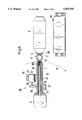
- FIG. 1 is a partial cross-sectional view of the device according to the invention with the two positions of movement of the mandrel wheel which is rotated only in the first position of movement, with the sealing tool arranged above it,
- FIG. 2 is an enlarged cross-sectional view two mandrels of the mandrel wheel in the first position of movement of the wheel, wherein the other two mandrels are broken away,
- FIG. 3 is an enlarged side view of the two deployed sealing tool halves with the end of the mandrel with the pouring device placed thereupon driven in to the correct height beneath the sealing tool halves,
- FIG. 4 is an enlarged side view of the sealing tool halves shown in FIG. 3 illustrating the subsequent condition of the sealing tool halves after the half shells of the pack and pouring device have been sealed together,
- FIG. 5 is a partially broken away cross-sectional view on a smaller scale showing the condition of the sealing tool as in FIG. 4, but with the mandrel wheel also showing with the capacity for translatory movement, and
- FIG. 6 is an enlarged cross-sectional view of the right-hand mandrel of the mandrel wheel, the other three mandrels of which are omitted, after the pouring device with the pack sealed thereto has been stripped off and a short time prior to further rotation through 90° in the direction of the curved arrow.
- the mandrel wheel 2 which is provided with four mandrels 1 which are arranged at angular spacings of 90° apart is rotatable in a step-wise manner through 90° about the axis of rotation 3 in the first position of movement and then in translatory fashion through the stroke H from the first position of movement in FIG. 1 shown by the solid lines into the position shown by way of broken lines, and back again, wherein in the second position of movement shown by broken lines the mandrel wheel 2 is not rotated about the axis of rotation 3'.
- a pouring device 6 has to be arranged in the hole, not shown, in the top 4 of a pack 5 for liquids, the pouring device consisting of a bottom 7 and a closure part 8 which is hinged by way of a hinge, not shown.
- next heating station II which is rotated in a clockwise-direction (second stage), then in translatory fashion in the direction of the arrow 12 up to the second position of movement of the axis of rotation 3' in such a way that the mandrel in question is then located at the heating station of the first stage II' ; whilst the outer end of the next mandrel 1 which is viewed in the clockwise direction is disposed at the sealing station III; whilst, finally, the mandrel arranged further in the clockwise direction is in the withdrawn position of the first position of movement of the axis of rotation 3, in the operative region of the stripper station IV i.e. the stripper station IV is in operative engagement here.
- the respective outer end of the mandrel 1 is thus disposed in positions for operative engagement successively with the set-down station I, then the heating station II', II, then the sealing station III and finally the stripper station IV.
- each mandrel 1 Provided on each mandrel 1 are means for stripping off the pouring device 6, but these only come into operation in the bottom 3 o'clock position when the axis of rotation 3 is once again disposed in the first position of movement.
- the individual phases of engagement will emerge more clearly in conjunction with the following description of the mode of operation.
- the mandrel wheel 2 together with its hub 9 is movable from the set-down station I in the direction of the sealing station III in the direction of the arrow 12 and back again in such a way that the axis of rotation 3 of the first position of movement is movable in a line towards the second position of movemeat of the axis of rotation 3', and this line is disposed in the central dividing plane 13 which is tensioned by the axis of rotation of the first position of movement 3 moving backwards and forwards in translatory fashion towards the axis of rotation 3' of the second position of movement, wherein the imaginary central plane can clearly also be imagined as existing above and below it.
- Two mandrels extend symmetrically in this central plane 13 and the two other mandrels extend vertically thereto.
- the central dividing plane 13 is thus identical to the plane of movement of the axis of rotation 3 of the mandrel wheel 2.
- the set-down station I has a loading device 15 with a push rod 16 which is movable backwards and forwards in a straight line in the direction of the two-directional arrow 14, the loading device and push rod being movable intermittently by a pneumatic drive, not shown, in the direction of the central dividing plane 13.
- a blade is arranged at the place denoted by the reference numeral 17 for cutting off a pouring device 6 from the one before it, before it is placed on the outer end of the mandrel 1.
- the heating station is constructed in two stages, namely the first stage of the pre-heating device II' which is shown to the top of FIGS. 1 and 5, and the second stage of the heating station II for final heating which is shown to the bottom left of FIGS. 1 and 5.
- the spacing between the two heating stages 2, 2' of the heating station is equal to the spacing H (FIG. 5) between the position of the axis of rotation 3 of the first position of movement and the position of the axis of rotation 3' of the second position of movement.
- Each stage of the heating station II. II' is identical in design to the other, i.e. the most important part is the thermal hollow body 18 which contains the pre-heating means in the first stage of the heating station II' and which contains the final heating means in the second stage of the heating station II.
- the thermal hollow body 18 is constructed in such a way that it is open at the front in relation to the respective mandrel 1 of the mandrel wheel 2, and the outer end of the mandrel 1 together with the pouring device 6 placed thereon, to be more exact, its bottom 7, can be accommodated in itself when the operational position of engagement is reached.
- the respective thermal hollow body 18 can be-moved backwards and forwards in a straight line vertically onto the central dividing plane 13, along the two-directional arrow 19.
- the pneumatic intermediate piston 20 inside the pneumatic cylinder 21 is able to move a crossbar 23 backwards and forwards by way of the piston rod 22 in such a way that the guide rod 24 moves the afore-mentioned thermal hollow body 18 from the retracted position of rest shown to the top left of FIG. 1 onto the axis of rotation 3' into the second position of movement vertically towards the central dividing plane 13 to the right, as shown to the bottom left of FIG. 1 in conjunction with the heating station II in the final heating stage.
- the sealing station denoted by the reference numeral III has two sealing tool halves 25 which are symmetrical with respect to the central dividing plane 13 and which have mutually facing handle-like openings 26 for each forming a pack half shell 27 in deep-drawing manner.
- Each sealing tool half 25 is connected by way of a drive rod 28 to a pneumatic cylinder 29 which is responsible for moving the two sealing tool halves 25 backwards and forwards in the direction of the two-directional arrows 30 through the stroke movement h.
- Both sealing tool halves 25 are able to move from the closed position shown in FIGS. 1, 4 and 5 through the stroke movement h into the open position shown in FIG. 3.
- Closure is, of course, effected in the reverse manner.
- the mutually facing front faces of the sealing tool halves 25 are moved towards each other until they meet and make reciprocal contact, wherein the front faces are then in alignment with the central dividing plane 13 (position in FIGS. 1, 4 and 5).
- the pack 5 for liquids is made completely from the deep-drawable plastics material described hereinabove.
- the pack is formed of two shell halves 27, the edges 31 of which are joined together (oppositely) (FIG. 3), so that the double-layer reinforcing rib 32 is formed which is shown in FIG. 4.
- this reinforcing rib 32 is interrupted by the opening device which basically consists of the closed pouring device 6 with the ready pack.
- the pouring device 6 is arranged on the pack 5, half and half on the half shells 27. The arrangement takes place by way of semi-cylindrical casing-like openings 33 on the side of the subsequent pack 5 which form the top 4 of same.
- FIG. 3 it can clearly be seen that the mandrel 1 has been moved in a translatory manner in the direction of the central dividing plane 13 upwardly to the sealing station III in The direction of the arrow 12 far enough for the semi-cylindrical casing-like surface (disposed on one side of the central dividing plane 13) of the bottom 7 of the pouring device 6 to be oppositely disposed to a corresponding annular collar 38 (FIG. 6) on the pack 5 or oppositely disposed to the half of the corresponding inner surface of the half shell 27.
- the sealing tool halves 25 are moved together from the position in FIG. 3 into the position in FIG. 4, and it will then be appreciated that the operation will take place whereby the annular bottom 7 of the pouring device 6 is sealed in the hole in the top 4 of the pack 5, whereby the device described here carries out its function.
- the stripper station can best be described with the aid of FIG. 6, wherein the axis of rotation 3 of the first position of movement of the hub 9 is shown for only one mandrel 1 for the purposes of clarity, this mandrel being, in the case of FIG. 1, the mandrel which projects to the right in the 3 o'clock position.
- the stripper station IV has a stripper sleeve 34 which is movable in sliding manner over the entire periphery of the mandrel 1 but which embraces it over only a part of its length, the stripper sleeve being shown in FIG. 6 in its retracted position.
- the drive generally denoted by the reference numeral 35 can also be arranged on each mandrel 1, in addition to the stripper sleeve 34, and it can rotate with the mandrel wheel 2: however, with the embodiment shown here, it is assumed that a drive 35 is only present in the region of position IV, i.e. in the effective operational position of the stripper station IV, by means of which drive operative engagement is produced in the 3 o'clock position alone, shown at the bottom of FIG. 1. This happens by way of the flange 36 of the stripper sleeve 34 which is arranged on the radially inner side towards the hub 9, relative to the sleeve thereon.
- the stripper sleeve 34 is able to be held in its retracted position at all times without engaging with the drive 35, in which position the outer end of the mandrel 1 is left free in the retracted starting position shown in FIG. 6, in such a way that the annular bottom 7 of the pouring device 6 is able to be pushed on (here just pushed off in FIG. 6).
- the gripping means 39 comes into operative engagement with the annular flange 36 of the stripper sleeve 34, the gripping means being movable backwards and forwards by the piston rod 40-from the pneumatic cylinder 41 in the direction of the two-directional arrow 42, radially in the direction of the mandrel 1.
- the tension spring 37 is tensioned to the flange 36, on the one hand, and to the mandrel 1, by way of the fixed screw 43.
- the axis of rotation 3 of the mandrel wheel 2 is to be imagined as lying horizontally in the drawings, so that the stripped off pack 5 shown to the right in FIG. 6 and adjacent to the mandrel 1 is horizontal can fall down vertically after it is stripped off, onto a progressive assembly line 44 or another suitable conveyance device.
- a string of pouring devices 6 is supplied in a supply 45 from a supply roll onto the set-down station I in a shape similar to that shown to the bottom left of FIG. 1.
- the bottom 7 is separated from the closure part 8, i.e. the two parts are hinged together so that they are disposed approximately vertically to each other.
- the bottom 7 is annular in such a way that even after sealing in the condition shown in FIG. 6, the inside of the pack 5 is accessible from the outside through the hole in the bottom 7 by a filling device and is able to be filled.
- the loading device 15 is moved in a straight line in the direction of the arrow 14 upwards radially to the axis of rotation 3 of the mandrel wheel 2 in its first position of movement, and therein uses the blade 17 to cut off the frontmost pouring device from the string of pouring devices 6 at a nominal breakage line, so that this pouring device is separated and is pushed directly onto the outer end of the mandrel 1.
- the loading device 15 is then withdrawn, so that the outer end of the mandrel is free again.
- the mandrel wheel 2 then rotates through 90° in the direction of the curved arrow 11. After the placement operation is terminated, the mandrel wheel begins to rotate and continues to do so until the next position of rotation is reached. The end of the mandrel in question is then disposed together with the pouring device 6 placed upon it in front of the second stage comprising the heating station II, without heating taking place there. Instead, directly after the rotational movement has been completed, the translatory movement of the mandrel wheel 2 commences in the direction of the arrow 12 upwards in FIG. 1 until it reaches the position marked by broken lines, where the axis of rotation 3' has reached its second position of movement.
- the mandrel 1 in question is then disposed in that position, in front of the first pre-heating stage of the heating station 2'. This is activated in the way described so that the thermal hollow body 18 embraces the annular outer surface of the bottom 7 and pre-heats it.
- the half shells 27 of the pack have been shaped on both sides by deep-drawing, and are disposed at a relatively high temperature in the sealing tool 25.
- the mandrel wheel 2 After the thermal hollow body 18 has been withdrawn from the heating station II--and also after a new pouring device 6 has been pushed onto the next mandrel 1 during the final heating operation, the mandrel wheel 2 begins to rotate a second time in the direction of the arrow 11, through 90°, so that the mandrel wheel in question here has now reached the upper 12 o'clock position.
- the mandrel wheel 2 in turn moves in translatory fashion in the direction of the arrow 12 into the position shown by broken lines in FIG. 1, where the two sealing tool halves 25 have previously adopted the position in FIG. 3, so that the mandrel 1 can move to the desired height between the sealing tool halves 5 to the bottom next to the openings 33.
- the bottom 7 is of a temperature which is high enough for sealing to take place
- the respective half shell 27 is also of a temperature which is high enough for sealing by virtue of the residual heat
- the two sealing tool halves 25 open again, and arrive at the position like that in FIG. 3, only the pack 5 is arranged on the mandrel 1 by way of the fixture to the pouring device 6. Only-the tool halves 25 are then in the spread apart position, and the mandrel wheel 2 moves the new pack with its sealed on pouring device 6 in the central dividing plane, downwards in the direction opposite to the arrow 12.
- the mandrel wheel 2 then rotates the mandrel 1 in question into the 3 o'clock position, so that the stripper station IV, i.e. the drive 35 comes into operative engagement with the stripper sleeve 34 (FIG. 6).
- the stripping process is initiated in the above-described way by actuating the pneumatic cylinder 41, so that the flange 36 of the stripper sleeve 34 is moved to the right in the direction of the arrow 42 in such a way that the pouring device 6 together with the pack 5 arranged thereon is pushed away horizontally from the mandrel 1 into the position shown to the right in FIG. 6.
- the spring 37 is extended and tensioned. Whilst the pack 5 together with its pouring device 6 falls down onto the conveyor belt 44 and is carried away, the spring 37 pulls the stripper sleeve 34, with the pneumatic cylinder 41 switched off, into the retracted starting position.
- the pouring device 6 in question can be held to the outer end of the mandrel 1 by a mechanical clamping effect.
- a vacuum pipe 46 can also be used to hold the pouring device by vacuum effect to the outer end of the mandrel 1.
- the pouring device 6 can also be kept cool by coolant pipes 47.
Landscapes
- Engineering & Computer Science (AREA)
- Mechanical Engineering (AREA)
- Making Paper Articles (AREA)
- Lining Or Joining Of Plastics Or The Like (AREA)
Applications Claiming Priority (2)
| Application Number | Priority Date | Filing Date | Title |
|---|---|---|---|
| DE4228181.4 | 1992-08-25 | ||
| DE4228181A DE4228181A1 (de) | 1992-08-25 | 1992-08-25 | Vorrichtung zum Anbringen einer Ausgießeinrichtung an einer Packung |
Publications (1)
| Publication Number | Publication Date |
|---|---|
| US5492592A true US5492592A (en) | 1996-02-20 |
Family
ID=6466366
Family Applications (1)
| Application Number | Title | Priority Date | Filing Date |
|---|---|---|---|
| US08/108,451 Expired - Fee Related US5492592A (en) | 1992-08-25 | 1993-08-19 | Method and device for arranging a pouring device on a pack |
Country Status (6)
| Country | Link |
|---|---|
| US (1) | US5492592A (de) |
| EP (1) | EP0589157A1 (de) |
| JP (1) | JPH06210735A (de) |
| AU (1) | AU666553B2 (de) |
| CA (1) | CA2101891A1 (de) |
| DE (1) | DE4228181A1 (de) |
Cited By (10)
| Publication number | Priority date | Publication date | Assignee | Title |
|---|---|---|---|---|
| US5829228A (en) * | 1996-04-25 | 1998-11-03 | Tetra Laval Holdings & Finance, Sa | Method and apparatus for forming the top of a container |
| US5867966A (en) * | 1996-04-25 | 1999-02-09 | Tetra Laval Holdings & Finance Sa | Method and apparatus for forming the top of a container |
| US5943840A (en) * | 1996-04-25 | 1999-08-31 | Tetra Laval Holdings & Finance, Sa | Method and apparatus for forming the top of a container with a fitment thereon |
| US20050172573A1 (en) * | 2004-01-23 | 2005-08-11 | Tetra Laval Holdings & Finance, S.A. | Carton transfer unit |
| US20060016152A1 (en) * | 2004-07-20 | 2006-01-26 | Tetra Laval Holdings & Finance, S.A. | Molding unit for forming direct injection molded closures |
| US20090098990A1 (en) * | 2006-03-10 | 2009-04-16 | Anders Delen | Method of producing a package |
| US20100004108A1 (en) * | 2004-11-16 | 2010-01-07 | Elopack System Ag | Apparatus and Method |
| CN107107516A (zh) * | 2015-03-19 | 2017-08-29 | Sig技术股份公司 | 用于制造包装件的芯轴轮 |
| US9815579B2 (en) * | 2012-01-20 | 2017-11-14 | A&R Carton Lund AB | Apparatus and method for application of lids to containers |
| US11376808B2 (en) * | 2017-06-30 | 2022-07-05 | Sig Technology Ag | Device for producing packaging comprising an independent mandrel wheel drive |
Families Citing this family (4)
| Publication number | Priority date | Publication date | Assignee | Title |
|---|---|---|---|---|
| DE4410909C2 (de) * | 1994-03-29 | 1998-07-16 | Tetra Laval Holdings & Finance | Verfahren zum Anbringen einer Öffnungseinrichtung an eine Packungswand und Vorrichtung zur Durchführung des Verfahrens |
| DE4432718A1 (de) * | 1994-09-14 | 1996-03-21 | Tetra Laval Holdings & Finance | Packung mit flacher Öffnungsvorrichtung und Werkzeug zur Herstellung derselben |
| DE10358750B4 (de) * | 2003-12-12 | 2005-10-27 | Sig Technology Ltd. | Dornrad für die Herstellung des Packungsbodens von Mehrschichtverbundpackungen |
| AU2010230040A1 (en) * | 2009-03-26 | 2011-09-29 | Nestec S.A. | A jaw support for a pouch filler |
Citations (14)
| Publication number | Priority date | Publication date | Assignee | Title |
|---|---|---|---|---|
| FR687941A (fr) * | 1929-03-29 | 1930-08-14 | Procédé de fabrication de l'acide phosphorique et applications de ce procédé | |
| US2768106A (en) * | 1950-09-19 | 1956-10-23 | Jack D Sartakoff | Method of making a carboy |
| US2972184A (en) * | 1957-11-29 | 1961-02-21 | Andrew & Waitkens Machine Co I | Machine for mounting spouts in the tops of containers |
| DE1166452B (de) * | 1956-10-05 | 1964-03-26 | Reifenhaeuser Kg | Verfahren zum Herstellen von Hohlkoerpern aus zwei zueinander parallel aus einer Strangpresse ausgespritzten Kunststoffbaendern und Vorrichtungen zum Durchfuehren des Verfahrens |
| US3323274A (en) * | 1964-01-27 | 1967-06-06 | Beloit Corp | Vacuum plastic bottle forming machine and method |
| DE1479080A1 (de) * | 1963-10-26 | 1969-02-20 | Detag | Verfahren zur Herstellung von Hohlkoerpern aus thermoplastischem Kunststoff |
| US3557520A (en) * | 1968-11-12 | 1971-01-26 | Gillette Co | Methods and apparatus for manufacturing dispensing devices |
| US3919374A (en) * | 1973-04-23 | 1975-11-11 | Automatic Liquid Packaging | Method for blow molding a container having an auxiliary component formed as an integral part of it |
| FR2367601A1 (fr) * | 1976-10-13 | 1978-05-12 | Maegerle Karl | Appareil pour la fabrication de recipients d'emballage |
| US4238267A (en) * | 1978-07-18 | 1980-12-09 | Konstantin Anatole E | Apparatus for producing shrinkable plastic caps |
| US4959190A (en) * | 1987-12-18 | 1990-09-25 | Sotralentz S.A. | Process for making a plastic container by blow molding |
| DE3929664A1 (de) * | 1989-09-07 | 1991-03-14 | Schenk Helga | Verfahren und vorrichtung zur herstellung von behaeltern mit einem anschlusselement, wie zum beispiel einem fuell- und/oder entnahmestutzen |
| EP0433634A1 (de) * | 1989-12-20 | 1991-06-26 | Tetra Laval Holdings & Finance SA | Verfahren zur Herstellung einer Fliessmittelpackung und Verwendung einer Kunststoffplatte für das Herstellungsverfahren |
| US5297375A (en) * | 1991-04-11 | 1994-03-29 | Tetra Laval Holdings & Finance S.A. | Method and apparatus for closing a pack |
Family Cites Families (5)
| Publication number | Priority date | Publication date | Assignee | Title |
|---|---|---|---|---|
| GB1130412A (en) * | 1965-10-08 | 1968-10-16 | Rausing Anders Ruben | Improvements in and relating to the manufacture of containers |
| US3434908A (en) * | 1965-11-12 | 1969-03-25 | Summerhayes Holdings Ltd | Sealing head |
| GB2112344B (en) * | 1981-02-27 | 1985-01-30 | Shibuya Kogyo Co Ltd | Method and device for mounting a plug on a paper container |
| DE3217156A1 (de) * | 1982-05-07 | 1983-11-10 | Altstaedter Verpack Vertrieb | Packung fuer fliessfaehige fuellgueter mit wieder verschliessbarer oeffnungsvorrichtung |
| US5058360A (en) * | 1990-04-04 | 1991-10-22 | Toppan Printing Co., Ltd. | Filling and sealing apparatus for fluid containing package |
-
1992
- 1992-08-25 DE DE4228181A patent/DE4228181A1/de not_active Ceased
-
1993
- 1993-07-06 EP EP93110762A patent/EP0589157A1/de not_active Ceased
- 1993-07-19 AU AU42055/93A patent/AU666553B2/en not_active Ceased
- 1993-08-04 CA CA002101891A patent/CA2101891A1/en not_active Abandoned
- 1993-08-12 JP JP5200619A patent/JPH06210735A/ja not_active Withdrawn
- 1993-08-19 US US08/108,451 patent/US5492592A/en not_active Expired - Fee Related
Patent Citations (15)
| Publication number | Priority date | Publication date | Assignee | Title |
|---|---|---|---|---|
| FR687941A (fr) * | 1929-03-29 | 1930-08-14 | Procédé de fabrication de l'acide phosphorique et applications de ce procédé | |
| US2768106A (en) * | 1950-09-19 | 1956-10-23 | Jack D Sartakoff | Method of making a carboy |
| DE1166452B (de) * | 1956-10-05 | 1964-03-26 | Reifenhaeuser Kg | Verfahren zum Herstellen von Hohlkoerpern aus zwei zueinander parallel aus einer Strangpresse ausgespritzten Kunststoffbaendern und Vorrichtungen zum Durchfuehren des Verfahrens |
| US2972184A (en) * | 1957-11-29 | 1961-02-21 | Andrew & Waitkens Machine Co I | Machine for mounting spouts in the tops of containers |
| DE1479080A1 (de) * | 1963-10-26 | 1969-02-20 | Detag | Verfahren zur Herstellung von Hohlkoerpern aus thermoplastischem Kunststoff |
| US3323274A (en) * | 1964-01-27 | 1967-06-06 | Beloit Corp | Vacuum plastic bottle forming machine and method |
| US3557520A (en) * | 1968-11-12 | 1971-01-26 | Gillette Co | Methods and apparatus for manufacturing dispensing devices |
| US3919374A (en) * | 1973-04-23 | 1975-11-11 | Automatic Liquid Packaging | Method for blow molding a container having an auxiliary component formed as an integral part of it |
| FR2367601A1 (fr) * | 1976-10-13 | 1978-05-12 | Maegerle Karl | Appareil pour la fabrication de recipients d'emballage |
| US4152566A (en) * | 1976-10-13 | 1979-05-01 | Maegerle Karl | Apparatus for manufacturing an article |
| US4238267A (en) * | 1978-07-18 | 1980-12-09 | Konstantin Anatole E | Apparatus for producing shrinkable plastic caps |
| US4959190A (en) * | 1987-12-18 | 1990-09-25 | Sotralentz S.A. | Process for making a plastic container by blow molding |
| DE3929664A1 (de) * | 1989-09-07 | 1991-03-14 | Schenk Helga | Verfahren und vorrichtung zur herstellung von behaeltern mit einem anschlusselement, wie zum beispiel einem fuell- und/oder entnahmestutzen |
| EP0433634A1 (de) * | 1989-12-20 | 1991-06-26 | Tetra Laval Holdings & Finance SA | Verfahren zur Herstellung einer Fliessmittelpackung und Verwendung einer Kunststoffplatte für das Herstellungsverfahren |
| US5297375A (en) * | 1991-04-11 | 1994-03-29 | Tetra Laval Holdings & Finance S.A. | Method and apparatus for closing a pack |
Cited By (24)
| Publication number | Priority date | Publication date | Assignee | Title |
|---|---|---|---|---|
| US5829228A (en) * | 1996-04-25 | 1998-11-03 | Tetra Laval Holdings & Finance, Sa | Method and apparatus for forming the top of a container |
| US5867966A (en) * | 1996-04-25 | 1999-02-09 | Tetra Laval Holdings & Finance Sa | Method and apparatus for forming the top of a container |
| US5943840A (en) * | 1996-04-25 | 1999-08-31 | Tetra Laval Holdings & Finance, Sa | Method and apparatus for forming the top of a container with a fitment thereon |
| WO2000029293A1 (en) * | 1998-11-13 | 2000-05-25 | Tetra Laval Holdings And Finance, S.A. | Method and apparatus for forming the top of a container with a fitment thereon |
| US7128200B2 (en) | 2004-01-23 | 2006-10-31 | Tetra Laval Holdings & Finance, Sa | Carton transfer unit |
| US20050172572A1 (en) * | 2004-01-23 | 2005-08-11 | Tetra Laval Holdings & Finance, S.A. | Carton transfer unit |
| WO2005073090A1 (en) * | 2004-01-23 | 2005-08-11 | Tetra Laval Holdings & Finance, S.A. | Carton transfer unit |
| US20060006049A1 (en) * | 2004-01-23 | 2006-01-12 | Tetra Laval Holdings & Finance, S.A. | Carton transfer unit |
| NO339858B1 (no) * | 2004-01-23 | 2017-02-06 | Tetra Laval Holdings & Finance | Kartongoverføringsenhet |
| US7059466B2 (en) | 2004-01-23 | 2006-06-13 | Tetra Laval Holdings & Finance, Sa | Carton transfer unit |
| US7077259B2 (en) | 2004-01-23 | 2006-07-18 | Tetra Laval Holdings & Finance, Sa | Carton transfer unit |
| US7080726B2 (en) | 2004-01-23 | 2006-07-25 | Tetra Laval Holdings & Finance, Sa | Carton transfer unit |
| US20050172573A1 (en) * | 2004-01-23 | 2005-08-11 | Tetra Laval Holdings & Finance, S.A. | Carton transfer unit |
| US7313895B2 (en) | 2004-07-20 | 2008-01-01 | Tetra Laval Holdings & Finance, Sa | Molding unit for forming direct injection molded closures |
| US20060016152A1 (en) * | 2004-07-20 | 2006-01-26 | Tetra Laval Holdings & Finance, S.A. | Molding unit for forming direct injection molded closures |
| US20100004108A1 (en) * | 2004-11-16 | 2010-01-07 | Elopack System Ag | Apparatus and Method |
| US8104250B2 (en) | 2004-11-16 | 2012-01-31 | Elopak Systems Ag | Apparatus for use in and method of attachiing cap-form fitments to containers |
| US20090098990A1 (en) * | 2006-03-10 | 2009-04-16 | Anders Delen | Method of producing a package |
| US7926244B2 (en) * | 2006-03-10 | 2011-04-19 | Tetra Laval Holdings & Finance S.A. | Method of producing a package |
| US9815579B2 (en) * | 2012-01-20 | 2017-11-14 | A&R Carton Lund AB | Apparatus and method for application of lids to containers |
| CN107107516A (zh) * | 2015-03-19 | 2017-08-29 | Sig技术股份公司 | 用于制造包装件的芯轴轮 |
| US10464264B2 (en) | 2015-03-19 | 2019-11-05 | Sig Technology Ag | Mandrel wheel for producing packages |
| CN107107516B (zh) * | 2015-03-19 | 2020-06-30 | Sig技术股份公司 | 用于制造包装件的芯轴轮 |
| US11376808B2 (en) * | 2017-06-30 | 2022-07-05 | Sig Technology Ag | Device for producing packaging comprising an independent mandrel wheel drive |
Also Published As
| Publication number | Publication date |
|---|---|
| AU4205593A (en) | 1994-03-10 |
| CA2101891A1 (en) | 1994-02-26 |
| AU666553B2 (en) | 1996-02-15 |
| DE4228181A1 (de) | 1994-03-03 |
| EP0589157A1 (de) | 1994-03-30 |
| JPH06210735A (ja) | 1994-08-02 |
Similar Documents
| Publication | Publication Date | Title |
|---|---|---|
| US5492592A (en) | Method and device for arranging a pouring device on a pack | |
| US3690088A (en) | Method of packaging | |
| CA1171387A (en) | Pack for fluid filling materials with reclosable opening device | |
| US4989994A (en) | Nested plastic bags and method of manufacture | |
| EP0505851B1 (de) | Öffnungsvorrichtung für einen Verpackungsbehälter und Verfahren zu ihrer Herstellung | |
| AU600905B2 (en) | Apparatus for the application of a gasket inside closures comprising a cup, such as screw-on and crown caps | |
| PL184895B1 (pl) | Sposób i urządzenie do formowania otwieracza w arkuszu materiału przeznaczonym na opakowanie | |
| US4391666A (en) | Container manufacturing machine | |
| US6824731B1 (en) | Entering injection moulded preforms in a mould of a high-efficiency blow-moulding apparatus | |
| FI82009B (fi) | Foerfarande och anordning foer fogning av en tubaenda samt en medelst foerfarandet tillverkad tub. | |
| FR2627429A1 (fr) | Fermeture d'extremite, procede pour son application sur des profiles tubulaires creux et dispositif pour executer ladite application | |
| US5297375A (en) | Method and apparatus for closing a pack | |
| US6546973B2 (en) | Equipment for filling flexible container with viscous material. | |
| RU2429966C2 (ru) | Способ и устройство для литья под давлением части упаковочного контейнера | |
| US8580179B2 (en) | Apparatus for moulding a part of a packaging container | |
| CA1303519C (en) | Packaging machine | |
| EP1188542B1 (de) | Maschine und Verfahren zum Herstellen von Behältern aus, von einer Wickelrolle kommenden, bahnförmigen Material | |
| US3863326A (en) | Device for manufacturing double-walled cups | |
| CA1084016A (en) | Method and apparatus for applying sleeves to necks of bottles and other containers | |
| CA1178410A (en) | Pack for fluid filling materials with reclosable opening device | |
| JPH0253288B2 (de) | ||
| EP1025978A3 (de) | Vorrichtung zum Thermoformen von Behältern aus einer Folienbahn aus thermoplastischem Kunststoff | |
| CN112937951A (zh) | 带盖杯子及带盖杯子封口机 | |
| JPS60154045A (ja) | 包装用容器製造装置におけるヒ−トシ−ル装置 | |
| IE52726B1 (en) | Pack for fluid filling materials with reclosable opening device |
Legal Events
| Date | Code | Title | Description |
|---|---|---|---|
| AS | Assignment |
Owner name: TETRA LAVAL HOLDINGS & FINANCE S.A., SWITZERLAND Free format text: ASSIGNMENT OF ASSIGNORS INTEREST;ASSIGNORS:BERGHOLTZ, LARS;KINDINGER, HANS;PFUHL, REINER;REEL/FRAME:006736/0988;SIGNING DATES FROM 19930729 TO 19930803 |
|
| FEPP | Fee payment procedure |
Free format text: PAYOR NUMBER ASSIGNED (ORIGINAL EVENT CODE: ASPN); ENTITY STATUS OF PATENT OWNER: LARGE ENTITY |
|
| FEPP | Fee payment procedure |
Free format text: PAYOR NUMBER ASSIGNED (ORIGINAL EVENT CODE: ASPN); ENTITY STATUS OF PATENT OWNER: LARGE ENTITY Free format text: PAYER NUMBER DE-ASSIGNED (ORIGINAL EVENT CODE: RMPN); ENTITY STATUS OF PATENT OWNER: LARGE ENTITY |
|
| FPAY | Fee payment |
Year of fee payment: 4 |
|
| FPAY | Fee payment |
Year of fee payment: 8 |
|
| REMI | Maintenance fee reminder mailed | ||
| LAPS | Lapse for failure to pay maintenance fees | ||
| STCH | Information on status: patent discontinuation |
Free format text: PATENT EXPIRED DUE TO NONPAYMENT OF MAINTENANCE FEES UNDER 37 CFR 1.362 |
|
| FP | Lapsed due to failure to pay maintenance fee |
Effective date: 20080220 |